EP0248415B1 - Mechanisch höhenverstellbare Kopfstütze für Kraftfahrzeugsitze - Google Patents
Mechanisch höhenverstellbare Kopfstütze für Kraftfahrzeugsitze Download PDFInfo
- Publication number
- EP0248415B1 EP0248415B1 EP87108020A EP87108020A EP0248415B1 EP 0248415 B1 EP0248415 B1 EP 0248415B1 EP 87108020 A EP87108020 A EP 87108020A EP 87108020 A EP87108020 A EP 87108020A EP 0248415 B1 EP0248415 B1 EP 0248415B1
- Authority
- EP
- European Patent Office
- Prior art keywords
- support
- headrest
- threaded
- support rod
- drive
- Prior art date
- Legal status (The legal status is an assumption and is not a legal conclusion. Google has not performed a legal analysis and makes no representation as to the accuracy of the status listed.)
- Expired - Lifetime
Links
- 229920003023 plastic Polymers 0.000 claims description 4
- 239000004033 plastic Substances 0.000 claims description 4
- 238000006073 displacement reaction Methods 0.000 claims description 2
- 230000008878 coupling Effects 0.000 claims 1
- 238000010168 coupling process Methods 0.000 claims 1
- 238000005859 coupling reaction Methods 0.000 claims 1
- 230000000977 initiatory effect Effects 0.000 claims 1
- 239000000463 material Substances 0.000 claims 1
- 239000002184 metal Substances 0.000 description 2
- 229910000831 Steel Inorganic materials 0.000 description 1
- 238000010276 construction Methods 0.000 description 1
- 238000002347 injection Methods 0.000 description 1
- 239000007924 injection Substances 0.000 description 1
- 238000005461 lubrication Methods 0.000 description 1
- 239000010959 steel Substances 0.000 description 1
- 239000013589 supplement Substances 0.000 description 1
Images


Classifications
-
- B—PERFORMING OPERATIONS; TRANSPORTING
- B60—VEHICLES IN GENERAL
- B60N—SEATS SPECIALLY ADAPTED FOR VEHICLES; VEHICLE PASSENGER ACCOMMODATION NOT OTHERWISE PROVIDED FOR
- B60N2/00—Seats specially adapted for vehicles; Arrangement or mounting of seats in vehicles
- B60N2/80—Head-rests
- B60N2/806—Head-rests movable or adjustable
- B60N2/809—Head-rests movable or adjustable vertically slidable
Definitions
- the invention relates to a mechanically height-adjustable headrest for motor vehicle seats, as has become known in accordance with the subject matter of claim 1 by DE-A-31 41 515.
- each downward-pointing support rod end is provided on the outside with a cord thread, which is encompassed by a radially elastically flexible, rotationally driven, axially immovably held nut on the seat body.
- Each nut is provided on the outside with a circumferential toothing, which meshes with a screw. Both threaded screws are coupled to each other in a torsionally rigid manner, a screw being driven by a flexible shaft, with the interposition of a flexible shaft, via a manual control wheel attached to the outside of the seat back.
- the support rods together with the cushion support held on them can thus be moved up and down via a central drive which is removed from the headrest and can be arranged at an ergonomically suitable location.
- the object of the invention is to create a headrest which is mechanically height-adjustable via a central drive and which overall permits a particularly simple and, moreover, compact design. This object has been achieved in accordance with the characterizing part of patent claim 1.
- the support rods in the headrest according to the invention are spatially fixed - but can be detached if necessary - held in the seat back.
- a support sleeve is mounted axially adjustable on each upper end of the support rod, the cushion support preferably being held tiltably or rigidly on the support sleeves.
- a centrally mechanically height-adjustable headrest with tubular support rods is already known per se from DE-A-32 46 766.
- this known headrest is not an internally adjustable headrest, but rather a headrest that is adjustable on the backrest.
- a support rod shown in DE-A-32 46 766 does not take a flexible shaft, but rather a rod-like, pressure-resistant rope, which is designed approximately in the manner of a toothed rack and with which a gear wheel, which is rotatably mounted in the cushion carrier, meshes with a handwheel on the outside on the outside.
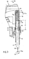
- Fig. 1-3 each a separate embodiment in an axial longitudinal section through a headrest (the padding is omitted) and
- FIG. 4 shows a central drive part that can be used equally for the embodiments according to FIGS. 1-3.
- a cushion support of a headrest for motor vehicle seats is designated by the reference number 10.
- the upholstery surrounding the upholstery carrier was not shown in order to simplify the drawing.
- the support member between the cushion support 10 and the support rods 11 is each formed by a support sleeve 12, which is arranged along the height axis y relatively adjustable on the support rod 11, enclosing it.
- the cushion support 10 has its lowest position with respect to the support rods 11.
- the cushion support 10 is connected to the two support sleeves 12 via a horizontal pivot bearing arrangement which is not shown and is arranged in the axis of rotation D to a limited extent and is adjustable.
- the cushion supports 10 have reached an inclination end so that only an inclination adjustment back in the direction z is possible.
- a flexible shaft 13 is received in each support rod 11, the output end of which is held by means of a square pin 14 in the cap base 15 of a threaded cap 16a, 16b or 16c.
- the threaded cap 16 a is rotatably supported on the upper smooth outer end region of the support rod 11 about the height axis y. and via resilient metal locking rings 17 (for example in accordance with DIN 472), each of which is located both in inner ring grooves 18 on the threaded cap side and in engage outer ring grooves 19 on the support rod side, secured against axial displacement, ie also secured against triggering.
- resilient metal locking rings 17 for example in accordance with DIN 472
- the threaded cap 16 a is provided with an external thread G a (spindle part), which cooperates with an internal thread G, (nut part) on the inner wall of the support sleeve 12.
- the support sleeve 12 moves upward in the height direction y when the flexible shaft 13 is driven in a certain direction of rotation with a torque M d and in this case the threaded cap 16 a, which is rotationally fixedly coupled to the shaft 13, in rotation offset about the axis y.
- the support sleeve 12 is traversed, for example, by a split pin 20 or by a leg of a spring pre-connector, which then runs against an support shoulder 21 on the support rod side to limit the height within an axial groove 34.
- the split pin 20 also forms an additional safeguard against unwanted removal of the cushion carrier 10 in the y direction.
- the support rod 11 according to FIGS. 1 to 3 expediently represents a seamlessly drawn steel tube, while the support sleeve 12 expediently consists of a suitable plastic, as does the cushion support 10.
- the threaded caps shown can in principle consist of a suitable metal, but in the present case they form injection molded parts from a tough, sturdy plastic (e.g. POM) that also has certain bearing or lubrication properties.
- POM tough, sturdy plastic
- the two drive ends 22 of the two flexible shafts 13 of each headrest are coupled with one another in terms of movement, namely in terms of gears.
- a bevel gear 24 is arranged on a seat fitting part 23.
- a drive not shown, is seated on a central adjusting shaft 25, for example in the form of a manual control wheel.
- a motorized drive of the actuating shaft 25 would of course also be conceivable.
- a ring gear 26 is seated on the actuating shaft 25, the teeth of which mesh with the teeth of two identical bevel gears 27.
- Each bevel gear 27 (only one bevel gear 27 can be seen from FIG. 4, the other is covered) is non-rotatably coupled to a drive end 22 of a flexible shaft 13, so that both drive ends 22 emit a torque Md of the same direction of rotation. In this way, a vertical adjustment of both support sleeves 12 on the rotating threaded caps 16a is ensured.
- the threaded cap 16b is also arranged coaxially to the vertical axis y of the support rod 11 in the exemplary embodiment according to FIG. 2. Only the geometric relationships in the exemplary embodiment according to FIG. 2 are different from that according to FIG. 1.
- the upper end region of each support rod 11 is provided with the external thread G a .
- the threaded cap 16b has an internal thread G, which is in engagement with the external thread G a .
- the rotary bearing of the threaded cap 16 b is designed as follows: the support sleeve 12 forms a circular cylindrical recess 30 between a lower support shoulder 28 and upper locking segment-like support shoulders 29. The shoulders 28, 29 serve to secure the threaded cap 16 b in the axial position.
- FIG. 3 is fundamentally similar to that shown in FIG. 2. However, with the exception that each support sleeve 12 is axially shortened, i.e. only has an axially short undercut locking pin 33, the locking collar 31 of which is non-releasably engaged in a locking groove 32 on the threaded cap side. Locking collar 31 and locking groove 32 also form a rotationally symmetrical, the height direction y coaxial rotary bearing for the threaded cap 16 c.
- the threaded cap 16c can be set in rotation with a torque M d introduced via 13 in a suitable direction of rotation, so that the threaded cap 16c with its internal thread G, in the vertical direction y, on the external thread on the support rod Screws G a upwards and in doing so moves the support sleeve 12 - and with it the cushion support 10 - via the rotary bearing 31, 32, which is tensile and pressure-resistant in the axial direction.
- the support sleeves 12 are in each case held in a non-rotatable manner relative to the support rods 11 simply because of their inclined mounting with respect to the cushion support 10.
Landscapes
- Engineering & Computer Science (AREA)
- Aviation & Aerospace Engineering (AREA)
- Transportation (AREA)
- Mechanical Engineering (AREA)
- Chair Legs, Seat Parts, And Backrests (AREA)
- Seats For Vehicles (AREA)
Priority Applications (1)
| Application Number | Priority Date | Filing Date | Title |
|---|---|---|---|
| AT87108020T ATE60287T1 (de) | 1986-06-03 | 1987-06-03 | Mechanisch hoehenverstellbare kopfstuetze fuer kraftfahrzeugsitze. |
Applications Claiming Priority (2)
| Application Number | Priority Date | Filing Date | Title |
|---|---|---|---|
| DE3618677 | 1986-06-03 | ||
| DE3618677A DE3618677C1 (de) | 1986-06-03 | 1986-06-03 | Mechanisch hoehenverstellbare Kopfstuetze fuer Kraftfahrzeugsitze |
Publications (3)
| Publication Number | Publication Date |
|---|---|
| EP0248415A2 EP0248415A2 (de) | 1987-12-09 |
| EP0248415A3 EP0248415A3 (en) | 1990-01-10 |
| EP0248415B1 true EP0248415B1 (de) | 1991-01-23 |
Family
ID=6302208
Family Applications (1)
| Application Number | Title | Priority Date | Filing Date |
|---|---|---|---|
| EP87108020A Expired - Lifetime EP0248415B1 (de) | 1986-06-03 | 1987-06-03 | Mechanisch höhenverstellbare Kopfstütze für Kraftfahrzeugsitze |
Country Status (4)
| Country | Link |
|---|---|
| EP (1) | EP0248415B1 (es) |
| AT (1) | ATE60287T1 (es) |
| DE (2) | DE3618677C1 (es) |
| ES (1) | ES2021299B3 (es) |
Cited By (2)
| Publication number | Priority date | Publication date | Assignee | Title |
|---|---|---|---|---|
| DE4305909A1 (de) * | 1993-02-26 | 1994-09-01 | Metallwerk Biebighaeuser Gmbh | Verstellbare Kraftfahrzeug-Kopfstütze |
| DE19853624A1 (de) * | 1998-11-20 | 2000-05-25 | Volkswagen Ag | Kopfstützenanordnung für eine Sitzrückenlehne mit einem motorischen Kopfstützen-Verstellantrieb |
Families Citing this family (1)
| Publication number | Priority date | Publication date | Assignee | Title |
|---|---|---|---|---|
| DE29722513U1 (de) * | 1996-12-23 | 1998-04-16 | Butz Peter Verwaltung | Kopfstütze für Fahrzeugsitze |
Family Cites Families (6)
| Publication number | Priority date | Publication date | Assignee | Title |
|---|---|---|---|---|
| DE2332610C3 (de) * | 1973-06-27 | 1978-07-20 | Eugen Otto 4010 Hilden Butz | Kopfstütze für Kraftfahrzeugsitze |
| SE420394B (sv) * | 1979-06-08 | 1981-10-05 | Saab Scania Ab | Nackskydd for en stol, foretredesvis en fordonsstol |
| DE3141515A1 (de) * | 1981-10-20 | 1983-04-28 | C. Rob. Hammerstein Gmbh, 5650 Solingen | Fahrzeugsitz mit hoehenverstellbarer kopfstuetze |
| DE3246766C2 (de) * | 1982-12-17 | 1986-12-11 | Daimler-Benz Ag, 7000 Stuttgart | Kopfstütze für einen Kraftfahrzeugsitz |
| FR2568528B1 (fr) * | 1984-08-03 | 1988-10-14 | Peugeot Cycles | Appui-tete reglable pour siege d'automobile ou analogue |
| DE3440182A1 (de) * | 1984-11-02 | 1986-05-07 | Bayerische Motoren Werke AG, 8000 München | Hoehenverstellbare kopfstuetze |
-
1986
- 1986-06-03 DE DE3618677A patent/DE3618677C1/de not_active Expired
-
1987
- 1987-06-03 EP EP87108020A patent/EP0248415B1/de not_active Expired - Lifetime
- 1987-06-03 DE DE8787108020T patent/DE3767566D1/de not_active Expired - Lifetime
- 1987-06-03 AT AT87108020T patent/ATE60287T1/de not_active IP Right Cessation
- 1987-06-03 ES ES87108020T patent/ES2021299B3/es not_active Expired - Lifetime
Cited By (2)
| Publication number | Priority date | Publication date | Assignee | Title |
|---|---|---|---|---|
| DE4305909A1 (de) * | 1993-02-26 | 1994-09-01 | Metallwerk Biebighaeuser Gmbh | Verstellbare Kraftfahrzeug-Kopfstütze |
| DE19853624A1 (de) * | 1998-11-20 | 2000-05-25 | Volkswagen Ag | Kopfstützenanordnung für eine Sitzrückenlehne mit einem motorischen Kopfstützen-Verstellantrieb |
Also Published As
| Publication number | Publication date |
|---|---|
| DE3767566D1 (de) | 1991-02-28 |
| EP0248415A2 (de) | 1987-12-09 |
| ES2021299B3 (es) | 1991-11-01 |
| ATE60287T1 (de) | 1991-02-15 |
| EP0248415A3 (en) | 1990-01-10 |
| DE3618677C1 (de) | 1987-09-17 |
Similar Documents
| Publication | Publication Date | Title |
|---|---|---|
| DE3519351C2 (es) | ||
| WO1981002093A1 (fr) | Dispositif de reglage pour les appuis de dos dans les dossier de chaises et analogues | |
| DE20308887U1 (de) | Motorisch verstellbare Stützeinrichtung für eine Polsterung eines Sitz- und/oder Liegemöbels | |
| DE3319397C2 (de) | Gelenkbeschlag für einen Sitz mit verstellbarer Rückenlehne, insbesondere Kraftfahrzeugsitz | |
| EP0269856B1 (de) | Höhenverstellbare Lenksäule für Kraftfahrzeuge | |
| DE4119748C2 (de) | Abklappbarer Rückspiegel | |
| DE3508515C2 (de) | Motorisch verstellbarer Sitz, insbesondere für Kraftfahrzeuge | |
| DE19738200C2 (de) | Fahrzeugsitz mit Kopfstütze | |
| DE4305909C2 (de) | Verstellbare Kraftfahrzeug-Kopfstütze | |
| EP0647542B1 (de) | Stellantrieb mit einem elektrischen Antriebsmotor und einem diesem nachgeordneten Getriebe | |
| EP0248415B1 (de) | Mechanisch höhenverstellbare Kopfstütze für Kraftfahrzeugsitze | |
| WO2010115409A1 (de) | Kopfstütze für kraftfahrzeuginsassen | |
| DE3109592C2 (es) | ||
| DE4437539C2 (de) | Fahrzeugsitz | |
| EP0752358A1 (de) | Einstellvorrichtung zur Neigungsverstellung eines schwenkbar angelenkten Mantelrohres einer Lenkspindel eines Kraftfahrzeuges | |
| DE2319775A1 (de) | Vorrichtung zum einstellen der neigung und lage eines gegenstandes gegenueber einer bezugsrichtung | |
| DE69007179T2 (de) | Mechanismen zur Längsverstellung von Fahrzeugsitzen. | |
| EP0498318B1 (de) | Vorrichtung zur Füllhöheneinstellung | |
| DE3743944A1 (de) | Verstellbares federbein | |
| DE2912545A1 (de) | Maschine zum feinbearbeiten der zahnflanken von verzahnten werkstuecken | |
| DE3002827C2 (es) | ||
| DE3734707A1 (de) | Sitz fuer fahrzeuge, insbesondere fahrersitz fuer panzerfahrzeuge oder dergleichen | |
| DE19858980C5 (de) | Fahrzeugsitz, insbesondere Kraftfahrzeugsitz, mit einer Einstellvorrichtung | |
| EP0395052B1 (de) | Verstellbarer Rückspiegel für ein Kraftfahrzeug | |
| DE1630907A1 (de) | Gelenkschlag fuer Sitze mit verstellbarer Lehne,insbesondere Kraftfahrzeugsitze |
Legal Events
| Date | Code | Title | Description |
|---|---|---|---|
| PUAI | Public reference made under article 153(3) epc to a published international application that has entered the european phase |
Free format text: ORIGINAL CODE: 0009012 |
|
| AK | Designated contracting states |
Kind code of ref document: A2 Designated state(s): AT BE CH DE ES FR GB GR IT LI LU NL SE |
|
| RBV | Designated contracting states (corrected) |
Designated state(s): AT DE ES FR GB IT SE |
|
| PUAL | Search report despatched |
Free format text: ORIGINAL CODE: 0009013 |
|
| AK | Designated contracting states |
Kind code of ref document: A3 Designated state(s): AT DE ES FR GB IT SE |
|
| 17P | Request for examination filed |
Effective date: 19900122 |
|
| 17Q | First examination report despatched |
Effective date: 19900629 |
|
| ITF | It: translation for a ep patent filed | ||
| GRAA | (expected) grant |
Free format text: ORIGINAL CODE: 0009210 |
|
| AK | Designated contracting states |
Kind code of ref document: B1 Designated state(s): AT DE ES FR GB IT SE |
|
| REF | Corresponds to: |
Ref document number: 60287 Country of ref document: AT Date of ref document: 19910215 Kind code of ref document: T |
|
| GBT | Gb: translation of ep patent filed (gb section 77(6)(a)/1977) | ||
| REF | Corresponds to: |
Ref document number: 3767566 Country of ref document: DE Date of ref document: 19910228 |
|
| ET | Fr: translation filed | ||
| PLBE | No opposition filed within time limit |
Free format text: ORIGINAL CODE: 0009261 |
|
| STAA | Information on the status of an ep patent application or granted ep patent |
Free format text: STATUS: NO OPPOSITION FILED WITHIN TIME LIMIT |
|
| 26N | No opposition filed | ||
| PGFP | Annual fee paid to national office [announced via postgrant information from national office to epo] |
Ref country code: GB Payment date: 19930520 Year of fee payment: 7 |
|
| PGFP | Annual fee paid to national office [announced via postgrant information from national office to epo] |
Ref country code: DE Payment date: 19930607 Year of fee payment: 7 |
|
| PGFP | Annual fee paid to national office [announced via postgrant information from national office to epo] |
Ref country code: FR Payment date: 19930609 Year of fee payment: 7 |
|
| PGFP | Annual fee paid to national office [announced via postgrant information from national office to epo] |
Ref country code: ES Payment date: 19930623 Year of fee payment: 7 |
|
| PGFP | Annual fee paid to national office [announced via postgrant information from national office to epo] |
Ref country code: AT Payment date: 19930625 Year of fee payment: 7 |
|
| PGFP | Annual fee paid to national office [announced via postgrant information from national office to epo] |
Ref country code: SE Payment date: 19930630 Year of fee payment: 7 |
|
| PG25 | Lapsed in a contracting state [announced via postgrant information from national office to epo] |
Ref country code: GB Effective date: 19940603 Ref country code: AT Effective date: 19940603 |
|
| PG25 | Lapsed in a contracting state [announced via postgrant information from national office to epo] |
Ref country code: SE Effective date: 19940604 Ref country code: ES Free format text: LAPSE BECAUSE OF EXPIRATION OF PROTECTION Effective date: 19940604 |
|
| EUG | Se: european patent has lapsed |
Ref document number: 87108020.6 Effective date: 19950110 |
|
| GBPC | Gb: european patent ceased through non-payment of renewal fee |
Effective date: 19940603 |
|
| PG25 | Lapsed in a contracting state [announced via postgrant information from national office to epo] |
Ref country code: FR Effective date: 19950228 |
|
| PG25 | Lapsed in a contracting state [announced via postgrant information from national office to epo] |
Ref country code: DE Effective date: 19950301 |
|
| EUG | Se: european patent has lapsed |
Ref document number: 87108020.6 |
|
| REG | Reference to a national code |
Ref country code: FR Ref legal event code: ST |
|
| REG | Reference to a national code |
Ref country code: ES Ref legal event code: FD2A Effective date: 19990601 |
|
| PG25 | Lapsed in a contracting state [announced via postgrant information from national office to epo] |
Ref country code: IT Free format text: LAPSE BECAUSE OF NON-PAYMENT OF DUE FEES;WARNING: LAPSES OF ITALIAN PATENTS WITH EFFECTIVE DATE BEFORE 2007 MAY HAVE OCCURRED AT ANY TIME BEFORE 2007. THE CORRECT EFFECTIVE DATE MAY BE DIFFERENT FROM THE ONE RECORDED. Effective date: 20050603 |