EP0247822A2 - Verfahren zum Herstellen einer Bandspule - Google Patents
Verfahren zum Herstellen einer Bandspule Download PDFInfo
- Publication number
- EP0247822A2 EP0247822A2 EP87304634A EP87304634A EP0247822A2 EP 0247822 A2 EP0247822 A2 EP 0247822A2 EP 87304634 A EP87304634 A EP 87304634A EP 87304634 A EP87304634 A EP 87304634A EP 0247822 A2 EP0247822 A2 EP 0247822A2
- Authority
- EP
- European Patent Office
- Prior art keywords
- tape reel
- reel
- wall
- capstan
- gate
- Prior art date
- Legal status (The legal status is an assumption and is not a legal conclusion. Google has not performed a legal analysis and makes no representation as to the accuracy of the status listed.)
- Withdrawn
Links
Images


Classifications
-
- B—PERFORMING OPERATIONS; TRANSPORTING
- B29—WORKING OF PLASTICS; WORKING OF SUBSTANCES IN A PLASTIC STATE IN GENERAL
- B29C—SHAPING OR JOINING OF PLASTICS; SHAPING OF MATERIAL IN A PLASTIC STATE, NOT OTHERWISE PROVIDED FOR; AFTER-TREATMENT OF THE SHAPED PRODUCTS, e.g. REPAIRING
- B29C45/00—Injection moulding, i.e. forcing the required volume of moulding material through a nozzle into a closed mould; Apparatus therefor
- B29C45/17—Component parts, details or accessories; Auxiliary operations
- B29C45/26—Moulds
-
- G—PHYSICS
- G11—INFORMATION STORAGE
- G11B—INFORMATION STORAGE BASED ON RELATIVE MOVEMENT BETWEEN RECORD CARRIER AND TRANSDUCER
- G11B23/00—Record carriers not specific to the method of recording or reproducing; Accessories, e.g. containers, specially adapted for co-operation with the recording or reproducing apparatus ; Intermediate mediums; Apparatus or processes specially adapted for their manufacture
- G11B23/02—Containers; Storing means both adapted to cooperate with the recording or reproducing means
- G11B23/037—Single reels or spools
Definitions
- This invention relates to a method of manufacturing a video tape reel, and more particularly it relates to a tape reel manufacturing method which permits manufacture of a component part of a tape reel having an improved gate position and construction with high accuracy characteristics; and the invention extends to a molding device for use in such method, and to a reel when so produced.
- a method of making a unitary component part of a tape reel by injection molding which said part is shaped to comprise a cylindrical hub closed at one end by means of an end wall and flanged at its other end to define a side plate for the reel, with the end wall being formed firstly, with an axially disposed protrusion defining a centre of rotation for the reel and secondly, with a plurality of upstanding fixing bosses disposed about the protrusion, and intended for interfitment with holes in a second companion side plate formed separately from and adapted subsequently to be fixed to the unitary component being molded, a capstan wall for receiving tape being molded on the side plate concentric with and surrounding the hub with radial reinforcing ribs extending between the hub (2) and the capstan wall; the wall of the capstan being interrupted between a pair of the ribs to leave a gap bounded by end points of the wall of the capstan; the method being characterised in that in order to mold the said unitary reel component
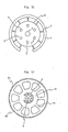
- the unitary molded component part of a tape reel includes a circular side plate 1, a cylinder 2 located in the centre thereof, and a tape core or capstan wall 4 surrounding the outer periphery of the cylinder 2 and spaced therefrom by ribs 3.
- a tape core or capstan wall 4 surrounding the outer periphery of the cylinder 2 and spaced therefrom by ribs 3.
- the unitary molded component part shown also has a plurality of fixing or caulking bosses 7 surrounding the axial protrusion 6 equally spaced therefrom.
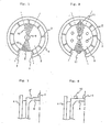
- capstan wall 4 is interrupted between two adjacent ribs 3, to define a gap bounded by end points 9 of the capstan wall 4 (see Figure 1).
- a second separately molded side plate (not shown in Figs 8 or 9, but indicated at 9 in Fig 5), which will have holes for receiving and interfitting with the fixing bosses 7, will be joined to a unitary component part such as is shown in Figs 8 or 9, to form a complete tape reel.
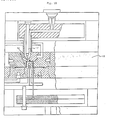
- Fig. 10 shows in cross-section, a hot runner molding device generally designated 15 for molding a unitary tape reel component part, such as is shown in Figs 8 or 9, according to the front gate injection molding system.
- the molding device 15 has a gate 16 and a hot chip 17. Resin is injected through the gate 16 uniformly into the whole cavity, a unitary component part as shown in Figs 8 or 9, for a tape reel, being thus formed.
- a cylindricity of less than 30 microns is required.
- the cylindricity of a tape reel manufactured by setting a gate on one of the caulking bosses 7 is of the order of 50-80 microns, and this may sometimes cause distortion and/or creasing of the tape during tape winding, resulting in tape damage and image distortion. Further, phenomena such as tape breaking have been observed during high-speed tape winding.
- the invention provides a method of manufacturing a component part for a tape reel component part, such as is shown in Figures 8 and 9, in which one or more gate positions is/are formed within two regions on the end wall 5 of the reel which is normal to the reel axis and carries the reel fixing bosses 7, said regions being each sectorial in shape and being areas bounded or defined by notional lines (or extensions thereof) connecting the axis of the tape reel and both ends of a gap formed in a wall 4 of a tape capstan, which wall is concentric with the reel axis.
- the invention extends to a device for performing the said method and it encompasses components and reels made directly thereby.
- Figures 1, 2 and 6 are schematic views showing a range of gate positions used in tape reel molding according to the invention.
- Figure 1 shows diagrammatically a first preferred range of locations for gating positions for use when forming a tape reel component part by injection molding. This range is to be found as indicated in Fig 1, at or on the end wall 5 at locations in sectorial regions 10, being two areas within and bounded by notional lines (and extensions thereof) connecting the axis of the tape reel and both end points 9 of the gap in the capstan wall 4, said sectorial regions 10 being shaded in Figures 1, 2 and 6.
- Gating may be located at a position to co-incide with that of a fixing or caulking boss 7 where such is present within the sectorial regions 10, and a gate may be placed on the top end of the boss.
- Another problem is that where the caulking boss is broken at the time of gate cutting, the volume of the caulking boss is smaller than intended resulting in inefficient interfitting or caulking with the companion side plate part, which is a cause of looseness with an opposite side plates of the reel being made.
- gating may be located at protrusions 11 as shown in Fig. 2 which protrusions may be provided on the outer periphery of the end wall 5 where it joins the inner cylinder 2.
- gating may be arranged to take place at a recess 5 ⁇ formed for the purpose on end wall 5 at a location within one of the two sectorial regions 10.
- a recess 5 ⁇ allows for gate residue and is provided on the end wall 5 as shown in Fig. 3.
- gating may be located to coincide with that of a dummy boss 12 as shown in Figure 4, and which is located in one of the sectorial regions 10.
- the height of the dummy boss 12 must be lower than the centre boss 6; and preferably (see position a in Fig. 5), its top is located at or below the level of the top of an inter-fitting companion side plate 13 as shown in Fig. 5 , which illustrates the condition when the two opposite side plates have been interfitted, ( the locking bosses 7 on wall 5 of a component, such as that shown in Figures 8 and 9, having been engaged and recieved in corresponding holes of the opposite side plate such as the side plate 13), to form the completed reel.
- either a single-point gate arrangement or a multi-point gate arrangement may be used and selection thereof may be determined in consideration of the position of each caulking boss, the configuration of the ceiling plate, and having regard to possible problems due to gate residues.
- the molding method used in the tape reel manufacturing method according to the invention may be of either the hot-runner type of the cold-runner type, there being no particular limitation attached thereto.
- the resin material used for the purpose of the invention may be any thermoplastic resin conventionally used.
- examples of such resin include ABS, polyacetal (homo- or co-polymer), polypropylene, polyethylene, polyalkylene terephthalate, such as polybutylene terephthalate, and polyamides.
- any known filler may be used for mixture.
- Particularly preferred resins are polyacetals.
- Gates were placed on the respective tops of caulking bosses shown by 14-1 ⁇ 14-6 in Fig. 6 and tape reels were thus molded.
- measurements were made in respect of roundness and cylindricity. Measurements were made at three positions b, c, d in Fig. 7.
- roundness and cylindricity measurements were made in accordance with JIS BO621.
- Moulding conditions were injection pressure 700 kg/cm2; injection rate 1 m/min; cycle time 10 sec. injection + 5 sec. cooling.
- Perforated reels referred to herein are reels having through-holes bored in their tape reel side plates, there being no limitation in configuration.
- the tape reels used in this example were such that the tape reel side plate comprised radial ribs 19 extending from the band-like member 18 and outer peripheral ribs 20.
- numeral 21 designates stop teeth.
Landscapes
- Engineering & Computer Science (AREA)
- Manufacturing & Machinery (AREA)
- Mechanical Engineering (AREA)
- Injection Moulding Of Plastics Or The Like (AREA)
- Storage Of Web-Like Or Filamentary Materials (AREA)
- Moulds For Moulding Plastics Or The Like (AREA)
Applications Claiming Priority (4)
| Application Number | Priority Date | Filing Date | Title |
|---|---|---|---|
| JP120433/86 | 1986-05-26 | ||
| JP61120433A JPH0763982B2 (ja) | 1986-05-26 | 1986-05-26 | テ−プリ−ルの製造方法 |
| JP61131273A JPH0632189B2 (ja) | 1986-06-06 | 1986-06-06 | テ−プリ−ルの製造方法 |
| JP131273/86 | 1986-06-06 |
Publications (2)
| Publication Number | Publication Date |
|---|---|
| EP0247822A2 true EP0247822A2 (de) | 1987-12-02 |
| EP0247822A3 EP0247822A3 (de) | 1989-05-17 |
Family
ID=26458019
Family Applications (1)
| Application Number | Title | Priority Date | Filing Date |
|---|---|---|---|
| EP87304634A Withdrawn EP0247822A3 (de) | 1986-05-26 | 1987-05-26 | Verfahren zum Herstellen einer Bandspule |
Country Status (1)
| Country | Link |
|---|---|
| EP (1) | EP0247822A3 (de) |
Cited By (3)
| Publication number | Priority date | Publication date | Assignee | Title |
|---|---|---|---|---|
| EP0549289A3 (en) * | 1991-12-19 | 1994-12-28 | Sony Corp | Magnetic tape cassette |
| US5462710A (en) * | 1992-11-10 | 1995-10-31 | Konica Corporation | Manufacturing method of a flange for use in a film cartridge |
| EP1867964A1 (de) * | 2006-06-12 | 2007-12-19 | Hitachi, Ltd. | Durchflussmesser, Durchgang der Durchflussmessung und Herstellungsverfahren |
Family Cites Families (5)
| Publication number | Priority date | Publication date | Assignee | Title |
|---|---|---|---|---|
| FR2418521A1 (fr) * | 1978-02-27 | 1979-09-21 | Hitachi Maxell | Noyau de bobine de cassette de bande |
| JPS5587352A (en) * | 1978-12-25 | 1980-07-02 | Nifco Inc | Tape reel for video cassette |
| US4452404A (en) * | 1982-08-20 | 1984-06-05 | Shape Inc. | Tape reel hub assembly |
| JPS6056989U (ja) * | 1983-08-22 | 1985-04-20 | 日立マクセル株式会社 | テ−プカ−トリツジ |
| JPS6140786U (ja) * | 1984-08-17 | 1986-03-14 | 富士写真フイルム株式会社 | テ−プリ−ル |
-
1987
- 1987-05-26 EP EP87304634A patent/EP0247822A3/de not_active Withdrawn
Cited By (5)
| Publication number | Priority date | Publication date | Assignee | Title |
|---|---|---|---|---|
| EP0549289A3 (en) * | 1991-12-19 | 1994-12-28 | Sony Corp | Magnetic tape cassette |
| US5456423A (en) * | 1991-12-19 | 1995-10-10 | Sony Corporation | Tape reel with thin flange portions |
| US5462710A (en) * | 1992-11-10 | 1995-10-31 | Konica Corporation | Manufacturing method of a flange for use in a film cartridge |
| EP1867964A1 (de) * | 2006-06-12 | 2007-12-19 | Hitachi, Ltd. | Durchflussmesser, Durchgang der Durchflussmessung und Herstellungsverfahren |
| US7571641B2 (en) | 2006-06-12 | 2009-08-11 | Hitachi, Ltd. | Flow measure instrument, passage of flow measure and production method |
Also Published As
| Publication number | Publication date |
|---|---|
| EP0247822A3 (de) | 1989-05-17 |
Similar Documents
| Publication | Publication Date | Title |
|---|---|---|
| US4932604A (en) | Tape cartridge | |
| JP3301873B2 (ja) | 樹脂巻き部品の成形方法 | |
| EP0274864B1 (de) | Bandspule für Bandkassette | |
| GB2040264A (en) | Tape reel for video cassette | |
| EP0247822A2 (de) | Verfahren zum Herstellen einer Bandspule | |
| JPS6143789B2 (de) | ||
| EP0247821A2 (de) | Verfahren zum Herstellen einer Bandspule | |
| US4760972A (en) | Recording tape cartridge and hub for use therein and method of making the hub | |
| US4162047A (en) | Hub for use in a tape casette | |
| US5077624A (en) | Magnetic tape device including outsert-molded tape guide catchers | |
| US5174520A (en) | Tape cassette reel having an upper reel portion formed by dichromatic molding method | |
| KR100473455B1 (ko) | 자기 테이프 카세트의 테이프 릴 | |
| EP0323101B1 (de) | Bandkassette mit Vorder- und Hinterklappe | |
| EP0549289B1 (de) | Magnetbandkassette | |
| KR920008574B1 (ko) | 테이프 릴 제작방법 | |
| US4959742A (en) | Rotary head mounting device | |
| KR950004529B1 (ko) | 단일부품으로 된 테이프 릴, 그 테이프 카세트 및 이들의 제조방법 | |
| EP0104472B1 (de) | Aufnahmebandkassette | |
| KR830000376Y1 (ko) | 비데오 카셋트용 테이프릴 | |
| US5071084A (en) | Reel for magnetic tape | |
| JPS63161558A (ja) | ビデオテ−プレコ−ダ用ドラムの成形方法 | |
| JP2010067346A (ja) | テープカートリッジ用テープリールのフランジとその成形金型 | |
| JPS60250923A (ja) | テ−プリ−ルの製法 | |
| JPH0429306A (ja) | ロータリートランス | |
| JPH08306160A (ja) | 磁気テープカセット |
Legal Events
| Date | Code | Title | Description |
|---|---|---|---|
| PUAI | Public reference made under article 153(3) epc to a published international application that has entered the european phase |
Free format text: ORIGINAL CODE: 0009012 |
|
| AK | Designated contracting states |
Kind code of ref document: A2 Designated state(s): AT BE CH DE ES FR GB GR IT LI LU NL SE |
|
| PUAL | Search report despatched |
Free format text: ORIGINAL CODE: 0009013 |
|
| AK | Designated contracting states |
Kind code of ref document: A3 Designated state(s): AT BE CH DE ES FR GB GR IT LI LU NL SE |
|
| 17P | Request for examination filed |
Effective date: 19891106 |
|
| STAA | Information on the status of an ep patent application or granted ep patent |
Free format text: STATUS: THE APPLICATION HAS BEEN WITHDRAWN |
|
| 18W | Application withdrawn |
Withdrawal date: 19900723 |
|
| R18W | Application withdrawn (corrected) |
Effective date: 19900723 |
|
| RIN1 | Information on inventor provided before grant (corrected) |
Inventor name: SANO, TERUTAKA |