EP0247770A2 - Reibungskupplungen - Google Patents
Reibungskupplungen Download PDFInfo
- Publication number
- EP0247770A2 EP0247770A2 EP87304362A EP87304362A EP0247770A2 EP 0247770 A2 EP0247770 A2 EP 0247770A2 EP 87304362 A EP87304362 A EP 87304362A EP 87304362 A EP87304362 A EP 87304362A EP 0247770 A2 EP0247770 A2 EP 0247770A2
- Authority
- EP
- European Patent Office
- Prior art keywords
- plate
- axially
- pressure plate
- cover member
- driven
- Prior art date
- Legal status (The legal status is an assumption and is not a legal conclusion. Google has not performed a legal analysis and makes no representation as to the accuracy of the status listed.)
- Withdrawn
Links
Images

Classifications
-
- F—MECHANICAL ENGINEERING; LIGHTING; HEATING; WEAPONS; BLASTING
- F16—ENGINEERING ELEMENTS AND UNITS; GENERAL MEASURES FOR PRODUCING AND MAINTAINING EFFECTIVE FUNCTIONING OF MACHINES OR INSTALLATIONS; THERMAL INSULATION IN GENERAL
- F16D—COUPLINGS FOR TRANSMITTING ROTATION; CLUTCHES; BRAKES
- F16D21/00—Systems comprising a plurality of actuated clutches
- F16D21/02—Systems comprising a plurality of actuated clutches for interconnecting three or more shafts or other transmission members in different ways
- F16D21/06—Systems comprising a plurality of actuated clutches for interconnecting three or more shafts or other transmission members in different ways at least two driving shafts or two driven shafts being concentric
- F16D2021/0607—Double clutch with torque input plate in-between the two clutches, i.e. having a central input plate
- F16D2021/0615—Double clutch with torque input plate in-between the two clutches, i.e. having a central input plate the central input plate is supported by bearings in-between the two clutches
-
- F—MECHANICAL ENGINEERING; LIGHTING; HEATING; WEAPONS; BLASTING
- F16—ENGINEERING ELEMENTS AND UNITS; GENERAL MEASURES FOR PRODUCING AND MAINTAINING EFFECTIVE FUNCTIONING OF MACHINES OR INSTALLATIONS; THERMAL INSULATION IN GENERAL
- F16D—COUPLINGS FOR TRANSMITTING ROTATION; CLUTCHES; BRAKES
- F16D21/00—Systems comprising a plurality of actuated clutches
- F16D21/02—Systems comprising a plurality of actuated clutches for interconnecting three or more shafts or other transmission members in different ways
- F16D21/06—Systems comprising a plurality of actuated clutches for interconnecting three or more shafts or other transmission members in different ways at least two driving shafts or two driven shafts being concentric
- F16D2021/0684—Mechanically actuated clutches with two clutch plates
Definitions
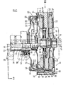
- the present invention relates to a friction clutch and in particular to a friction clutch assembly which will provide independent clutch control to a pair of concentric output shafts.
- a friction clutch assembly for independently controlling transmission of drive to a pair of concentric output shafts is characterised by a first driven plate adapted to be mounted on the inner output shaft so as to be capable of transmitting torsional loads thereto while being free to move axially thereof; a first pressure plate mounted co-axially with the first driven plate for engagement of a frictional surface thereof; a reaction plate mounted co-axially of the first driven plate and first pressure plate and spaced axially thereof; a second driven plate mounted co-axially of the reaction plate and adapted to be mounted on the outer output shaft so as to be capable of transmitting torsional loads thereto while being free to move axially thereof; a second pressure plate mounted co-axially of the second driven plate for engagement of a frictional surface thereof; first and second cover members mounted co-axially of one another; spring means acting against the first cover member to urge the second pressure plate and second driven plate against the reaction plate, thereby applying a clamping load to the second driven plate; spring means acting against the second cover
- the clutch assembly illustrated in the accompanying drawings is arranged to independently control transmission of drive between a flywheel 11 of an engine and a pair of concentric output shafts 12 and 13.
- the end of the inner shaft 12 is engaged in a spigot bearing 14 at the centre of the flywheel 11.
- the driven plate 15 is mounted on the shaft 12, an internally splined the hub 16 on the driven plate 15 engaging splines 17 on the shaft 12, so that torsional forces may be transmitted from the driven plate 15 to the shaft 12 while the driven plate 15 is free to move axially of the shaft 12.
- a reaction plate 18 in the form of a dished casting having cylindrical flange portion 20 is secured to the flywheel 11, concentrically of the shafts 12 and 13, at circumferentially spaced locations by means of bolts 19.
- An annular pressure plate 22 is interposed between the reaction plate 18 and driven plate 15, so that friction linings 23 on the driven plate 15 are sandwiched between opposed surfaces of the pressure plate 22 and the flywheel 11.
- the pressure plate 22 is drivingly connected to the reaction plate 18 by means of three sets of resilient straps 24 which extend between lugs 25 positioned symmetrically about the circumference of the pressure plate 22 and the reaction plate 18. These straps 24 locate the pressure plate 22 co-axially of the shafts 12 and 13 and permit a limited axial movement of the pressure plate 22 relative to the reaction plate 18.
- the straps 24 are also " arranged such that when pres'sure plate 22 clamps driven plate 15 into engagment with flywheel 11, the straps 24 will apply an axial load to the pressure plate 22 away from the driven plate 15. Portions of the flange portion 20 of reaction plate 18 are cut away to provide clearance for the lugs 25 and straps 24 and to permit connection of the straps 24 to the reaction plate 18.
- a bearing 26 is located on the internal diameter of the reaction plate 18 and is retained by circlip 27.
- the bearing 26 supports the end of the outer shaft 13.
- a second driven plate 30 is mounted upon the shaft 13, an internally splined hub 31 engaging with splines 32 on shaft 13, in similar manner to the interconnection between driven plate 15 and shaft 12.
- First and second cover members 35 and 36 are mounted with respect to the flywheel 11 and reaction plate 18 by means of bolts 19.
- Each cover member 35 and 36 has an inwardly directed flange portion 37 and 38 respectively, which are spaced axially of one another.
- a cylindrical wall member 39 maintains the axial separation between the flange portions 37 and 38.
- a second annular pressure-plate 40 is mounted co-axially of the shaft 13 so that the driven plate 30 is sandwiched between opposed faces of the pressure plate 40 and the reaction plate 18.
- the pressure plate 40 is drivingly connected to the cover member 35 by means of three sets of flexible straps 41 which are connected between symmetrically positioned lugs 42 on the pressure plate 40 and the cover member 35.
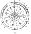
- the wall member 39 is interrupted and the periphery of cover member 35 is stepped away from the reaction plate 18 as illustrated in Figure 3.
- the straps 41 may be connected to cover member 35 by means of rivets 43 and also at this point, cover member 35 may be attached directly to cover member 36 by means of rivets 44, so that prior to attachment of the clutch assembly to the flywheel 11 the assembly will be held together, pressing 60 abutting the outer flange of cover member 35 to prevent overstressing of the drive straps 24.
- the straps 41 will locate the pressure plate 40 co-axially of shaft 13 and will also permit limited axial movement of the pressure plate 40.
- the straps 41 also apply an axial load to the pressure plate 40 away from the driven member 30.
- a diaphragm spring 50 having an outer Belleville portion 51 and inwardly directed fingers 52 is located between the flange 37 of cover member 35 and an annular projection 54 on pressure plate 40.
- the outer periphery of the Belleville portion 51 of diaphragm spring 50 engages the fulcrum ring 53 which is located against the flange 37.
- the diaphragm spring 50 is thereby arranged to act between the fulcrum ring 53 and the annular projection 54 to urge the pressure plate 40 axially away from the cover member 35, so as to force the driven plate 30 into frictional engagement with the reaction plate 18.
- a annular pressing 60 has an inwardly directed flange portion 61 and a cylindrical portion 62.
- the end of the cylindrical portion 62 remote from the flange portion 61 is castellated to provide a series of axially extending arcuate fingers 63 which extend through corresponding arcuate apertures 64 and 65 in the cover member 35 and reaction plate 18 respectively, these fingers 63 engaging in an annular groove 66 in the pressure plate 22.
- a diaphragm spring 67 of similar configuration to spring 50 acts between a fulcrum ring 68, located against the flange 38 of cover member 36 and an annular rib 69 on flange 61 of pressing 60 respectively, to urge the pressing 60 axially away from the cover member 36 and thus the pressure plate 22 and driven member 15 into frictional engagement with the flywheel 11.
- a pair of release bearings 70 and 71 are mounted co-axially of one another about shafts 12 and 13.
- Release bearing 70 is slidably mounted upon a sleeve 72 which surrounds the shafts 12 and 13.
- a pair of diametrically opposed radially extending abutments 73 are provided at one end of the release bearing 70. These abutments 73 are engaged by the yoke of an actuating lever 85, so that the lever 85 will move the bearing 70 axially.
- the other end of the release bearing 70 engages the inner peripheral portion of fingers 52 of diaphragm spring 50, said portions of fingers 52 being clamped between an abutment 76 and a Belleville spring 77.
- Release bearing 71 is slidingly mounted on release bearing 70, so that it is movable axially of the shafts 12 and 13, independently of release bearing 70.
- release bearing 71 is provided at one end with a pair of diametrically opposed radially extending abutments 78 which are engaged by the yoke of a second actuating lever 86.
- the other end of release bearing 71 engages the inner peripheral portion of diaphragm spring 67, the diaphragm spring 67 being engaged between an abutment 81 and a Belleville spring 82.
- Axial' movement of bearing 71 away from the flywheel 11 will relieve the load applied to the pressure plate 22 by the diaphragm spring 67 via the annular pressing 60. This will remove the clamping load on driven plate 15 and disengage the drive to shaft 12.
- the actuating levers 85, 86 may thus be used to control independently, transmission of drive to shafts 12 and 13.
Landscapes
- Engineering & Computer Science (AREA)
- General Engineering & Computer Science (AREA)
- Mechanical Engineering (AREA)
- Mechanical Operated Clutches (AREA)
Applications Claiming Priority (2)
| Application Number | Priority Date | Filing Date | Title |
|---|---|---|---|
| GB8612213A GB2190714B (en) | 1986-05-20 | 1986-05-20 | Friction clutches |
| GB8612213 | 1986-05-20 |
Publications (2)
| Publication Number | Publication Date |
|---|---|
| EP0247770A2 true EP0247770A2 (de) | 1987-12-02 |
| EP0247770A3 EP0247770A3 (de) | 1989-01-25 |
Family
ID=10598115
Family Applications (1)
| Application Number | Title | Priority Date | Filing Date |
|---|---|---|---|
| EP87304362A Withdrawn EP0247770A3 (de) | 1986-05-20 | 1987-05-18 | Reibungskupplungen |
Country Status (3)
| Country | Link |
|---|---|
| US (1) | US4787492A (de) |
| EP (1) | EP0247770A3 (de) |
| GB (1) | GB2190714B (de) |
Cited By (2)
| Publication number | Priority date | Publication date | Assignee | Title |
|---|---|---|---|---|
| EP0931951A1 (de) * | 1998-01-16 | 1999-07-28 | Ford Global Technologies, Inc. | Doppelkupplung in Reibscheibenbauart, insbesondere fuer Kraftfahrzeuge |
| DE19941837A1 (de) * | 1999-07-29 | 2001-02-01 | Rohs Voigt Patentverwertungsge | Kupplung, Anschlußelement sowie Anordnung hieraus und Verfahren zur Montage einer Kupplung |
Families Citing this family (23)
| Publication number | Priority date | Publication date | Assignee | Title |
|---|---|---|---|---|
| JPH03112133U (de) * | 1990-02-28 | 1991-11-15 | ||
| DE59913645D1 (de) * | 1998-04-17 | 2006-08-17 | Rohs Voigt Patentverwertungsge | Ausrückeinehit für eine Kupplungsdruckplatte sowie Betätigung dafür |
| US6012561A (en) * | 1998-09-15 | 2000-01-11 | Chrysler Corporation | Dual clutch design for and electro-mechanical automatic transmission having a dual input shaft |
| DE10013576B4 (de) * | 1999-03-26 | 2013-02-07 | Schaeffler Technologies AG & Co. KG | Kupplungsaggregat |
| FR2797004A1 (fr) * | 1999-07-29 | 2001-02-02 | Rohs Voigt Patentverwertungsge | Embrayage, element de raccordement et dispositif forme de ceux-ci, et procede d'assemblage d'un embrayage |
| DE10036504B4 (de) * | 1999-08-02 | 2011-05-19 | Schaeffler Technologies Gmbh & Co. Kg | Antriebsstrang |
| FR2803346B1 (fr) * | 1999-12-30 | 2002-04-26 | Valeo | Embrayage double, en particulier pour vehicule automobile |
| DE10016607B4 (de) * | 2000-04-04 | 2013-02-21 | Zf Sachs Ag | Doppelkupplungsanordnung |
| DE10016604B4 (de) * | 2000-04-04 | 2011-09-22 | Zf Sachs Ag | Doppelkupplungsanordnung |
| RU2002129876A (ru) * | 2000-04-10 | 2004-03-20 | Лук Ламеллен Унд Купплюнгсбау Бетайлигунгс Кг (De) | Агрегат сцепления |
| FR2810708B1 (fr) * | 2000-06-22 | 2002-10-25 | Peugeot Citroen Automobiles Sa | Dispositif de transmission et de maintien du couple |
| FR2810707B1 (fr) * | 2000-06-22 | 2002-10-25 | Peugeot Citroen Automobiles Sa | Dispositif de transmission et de maintien du couple |
| DE10036675B4 (de) * | 2000-07-27 | 2012-05-03 | Zf Friedrichshafen Ag | Ausrückeranordnung für eine Doppelkupplungsanordnung |
| DE10143834A1 (de) † | 2001-09-07 | 2003-03-27 | Zf Sachs Ag | Kupplungssystem mit einer nasslaufenden oder/und hydraulisch betätigbaren Mehrfach-Kupplungseinrichtung |
| WO2003081067A1 (de) * | 2002-03-27 | 2003-10-02 | Luk Lamellen Und Kupplungsbau Beteiligungs Kg | Doppelkupplungssystem für ein getriebe, insbesondere für ein doppelkupplungsgetriebe |
| US7322456B2 (en) * | 2005-09-29 | 2008-01-29 | Gm Global Technology Operations, Inc. | Radially stacked dual dry clutch configuration |
| JP5238963B2 (ja) * | 2006-11-30 | 2013-07-17 | シェフラー テクノロジーズ アクチエンゲゼルシャフト ウント コンパニー コマンディートゲゼルシャフト | トルク伝達装置 |
| BRPI0810388A2 (pt) | 2007-04-17 | 2014-11-04 | Valeo Embrayages | Dispositivo de embreagem de fricção, notadamente para um veículo automotivo |
| CN102132058B (zh) † | 2008-08-22 | 2014-03-19 | 舍弗勒技术股份两合公司 | 双离合器 |
| US8844390B2 (en) * | 2010-10-13 | 2014-09-30 | Hyundai Wia Corporation | Dual clutch transmission and dual clutch accuators thereof |
| WO2015170176A1 (ko) * | 2014-05-09 | 2015-11-12 | 발레오 평화 주식회사 | 더블 클러치 조립체 |
| DE102014215884A1 (de) * | 2014-08-11 | 2016-02-11 | Schaeffler Technologies AG & Co. KG | Doppelkupplung mit in Umfangsrichtung ausgerichteter und axial abstehender Lasche einer Gegendruckplatte |
| CN105387095B (zh) * | 2015-12-09 | 2018-05-22 | 无锡民联轴承制造有限公司 | 干式双离合器组合分离轴承 |
Family Cites Families (17)
| Publication number | Priority date | Publication date | Assignee | Title |
|---|---|---|---|---|
| GB1037523A (de) * | ||||
| US2613778A (en) * | 1944-12-07 | 1952-10-14 | Borg Warner | Multiple friction clutch |
| GB635042A (en) * | 1948-02-13 | 1950-03-29 | Borg & Beck Co Ltd | Improvements in or relating to friction clutches |
| DE819777C (de) * | 1950-01-19 | 1951-11-05 | Kloeckner Humboldt Deutz Ag | Fahrzeug mit Antrieb durch eine Brennkraftmaschine |
| GB755037A (en) * | 1953-06-26 | 1956-08-15 | Borg Warner | Improvements in or relating to clutches |
| FR1300975A (fr) * | 1961-07-01 | 1962-08-10 | Ferodo Sa | Perfectionnements aux embrayages |
| DE1256084B (de) * | 1962-09-14 | 1967-12-07 | Porsche Kg | Doppelkupplung fuer Ackerschlepper |
| FR1473218A (fr) * | 1966-01-27 | 1967-03-17 | Saviem | Commande de prise de mouvement à fonctionnement indépendant, incorporée à une boîte de vitesses |
| SE340728B (de) * | 1967-03-03 | 1971-11-29 | Fichtel & Sachs Ag | |
| DE1780276A1 (de) * | 1968-08-24 | 1971-12-30 | Porsche Kg | Kupplungsaggregat fuer Verbundgetriebe |
| LU61710A1 (de) * | 1970-09-18 | 1972-06-27 | ||
| US3841455A (en) * | 1970-11-24 | 1974-10-15 | Brown Tractors Ltd | Clutch with engine oil cooling |
| GB1537704A (en) * | 1976-02-14 | 1979-01-04 | Brown Tractors Ltd | Clutches |
| FR2397563A1 (fr) * | 1977-07-13 | 1979-02-09 | Ferodo Sa | Embrayage a deux disques de friction et mecanisme propre a la constitution d'un tel embrayage |
| GB2006895B (en) * | 1977-11-01 | 1982-05-12 | Gkn Transmissions Ltd | Friction clutches |
| DE3013299A1 (de) * | 1980-04-05 | 1981-10-15 | LuK Lamellen und Kupplungsbau GmbH, 7580 Bühl | Reibungskupplungseinheit |
| FR2492922A1 (fr) * | 1980-10-24 | 1982-04-30 | Valeo | Mecanisme d'embrayage pour embrayage a deux disques de friction, notamment pour vehicule automobile |
-
1986
- 1986-05-20 GB GB8612213A patent/GB2190714B/en not_active Expired - Lifetime
-
1987
- 1987-05-18 EP EP87304362A patent/EP0247770A3/de not_active Withdrawn
- 1987-05-19 US US07/051,394 patent/US4787492A/en not_active Expired - Fee Related
Cited By (2)
| Publication number | Priority date | Publication date | Assignee | Title |
|---|---|---|---|---|
| EP0931951A1 (de) * | 1998-01-16 | 1999-07-28 | Ford Global Technologies, Inc. | Doppelkupplung in Reibscheibenbauart, insbesondere fuer Kraftfahrzeuge |
| DE19941837A1 (de) * | 1999-07-29 | 2001-02-01 | Rohs Voigt Patentverwertungsge | Kupplung, Anschlußelement sowie Anordnung hieraus und Verfahren zur Montage einer Kupplung |
Also Published As
| Publication number | Publication date |
|---|---|
| US4787492A (en) | 1988-11-29 |
| GB2190714A (en) | 1987-11-25 |
| GB8612213D0 (en) | 1986-06-25 |
| GB2190714B (en) | 1990-06-20 |
| EP0247770A3 (de) | 1989-01-25 |
Similar Documents
| Publication | Publication Date | Title |
|---|---|---|
| US4787492A (en) | Double friction clutch with individual control | |
| US8448770B2 (en) | Multiplate clutch | |
| US6070708A (en) | Twin-clutch | |
| US6016897A (en) | Clutch mechanism for friction clutch with low clutching force | |
| US5366054A (en) | Friction clutch cover assemblies | |
| US6260684B1 (en) | Clutch mechanism for friction clutch | |
| US5509518A (en) | Diaphragm clutch assembly with wear compensator | |
| JP3227306B2 (ja) | クラッチ押圧組立体 | |
| US4662497A (en) | Friction clutches | |
| US6161669A (en) | Clutch mechanism for clutch friction with low declutching effort | |
| EP0662201A1 (de) | Kohlenstoff-kohlenstoff reibmechanismus | |
| EP0048563B1 (de) | Reibungskupplung | |
| WO1987007929A1 (en) | Clutch | |
| US3976174A (en) | Clutch disc with coaxial brake | |
| US4555005A (en) | Friction clutches | |
| US4809834A (en) | Multiple plate clutch release proportioning device | |
| JPH01316525A (ja) | クラッチ・アセンブリ | |
| US5373927A (en) | Clutch release assembly | |
| GB2191252A (en) | Friction clutch | |
| GB2203503A (en) | Variable ratio clutch lever | |
| US4923044A (en) | Clutch control device, especially for automotive vehicles | |
| US6079538A (en) | Clutch mechanism for friction clutch with low declutching force | |
| US5129499A (en) | Diaphragm spring clutch | |
| EP0724692B1 (de) | Tellerfederkupplung mit verschleissausgleichseinrichtung | |
| EP0075387A1 (de) | Reibungskupplung |
Legal Events
| Date | Code | Title | Description |
|---|---|---|---|
| PUAI | Public reference made under article 153(3) epc to a published international application that has entered the european phase |
Free format text: ORIGINAL CODE: 0009012 |
|
| AK | Designated contracting states |
Kind code of ref document: A2 Designated state(s): DE ES FR GB IT |
|
| PUAL | Search report despatched |
Free format text: ORIGINAL CODE: 0009013 |
|
| AK | Designated contracting states |
Kind code of ref document: A3 Designated state(s): DE ES FR GB IT |
|
| 17P | Request for examination filed |
Effective date: 19890710 |
|
| STAA | Information on the status of an ep patent application or granted ep patent |
Free format text: STATUS: THE APPLICATION IS DEEMED TO BE WITHDRAWN |
|
| 18D | Application deemed to be withdrawn |
Effective date: 19901203 |
|
| RIN1 | Information on inventor provided before grant (corrected) |
Inventor name: BALL, ROBERT JOLYON Inventor name: BANKS, JOHN DAVID |