EP0247675A1 - Sender für S-Bus-Schnittstelle in einem dienstintegrierenden Digitalnetz (ISDN) - Google Patents
Sender für S-Bus-Schnittstelle in einem dienstintegrierenden Digitalnetz (ISDN) Download PDFInfo
- Publication number
- EP0247675A1 EP0247675A1 EP19870200912 EP87200912A EP0247675A1 EP 0247675 A1 EP0247675 A1 EP 0247675A1 EP 19870200912 EP19870200912 EP 19870200912 EP 87200912 A EP87200912 A EP 87200912A EP 0247675 A1 EP0247675 A1 EP 0247675A1
- Authority
- EP
- European Patent Office
- Prior art keywords
- transmitter
- switching elements
- circuit
- binary
- transverse branch
- Prior art date
- Legal status (The legal status is an assumption and is not a legal conclusion. Google has not performed a legal analysis and makes no representation as to the accuracy of the status listed.)
- Granted
Links
- 239000004065 semiconductor Substances 0.000 claims abstract description 3
- 238000004804 winding Methods 0.000 claims description 10
- 238000009877 rendering Methods 0.000 claims description 4
- 239000013078 crystal Substances 0.000 claims description 2
- 230000005540 biological transmission Effects 0.000 description 11
- 230000011664 signaling Effects 0.000 description 3
- 230000008901 benefit Effects 0.000 description 2
- 238000006243 chemical reaction Methods 0.000 description 2
- 230000007704 transition Effects 0.000 description 2
- 230000008859 change Effects 0.000 description 1
- 238000011181 container closure integrity test Methods 0.000 description 1
- 230000008878 coupling Effects 0.000 description 1
- 238000010168 coupling process Methods 0.000 description 1
- 238000005859 coupling reaction Methods 0.000 description 1
- 238000010586 diagram Methods 0.000 description 1
- 238000000926 separation method Methods 0.000 description 1
Images
Classifications
-
- H—ELECTRICITY
- H04—ELECTRIC COMMUNICATION TECHNIQUE
- H04L—TRANSMISSION OF DIGITAL INFORMATION, e.g. TELEGRAPHIC COMMUNICATION
- H04L25/00—Baseband systems
- H04L25/02—Details ; arrangements for supplying electrical power along data transmission lines
- H04L25/0264—Arrangements for coupling to transmission lines
- H04L25/028—Arrangements specific to the transmitter end
-
- H—ELECTRICITY
- H04—ELECTRIC COMMUNICATION TECHNIQUE
- H04L—TRANSMISSION OF DIGITAL INFORMATION, e.g. TELEGRAPHIC COMMUNICATION
- H04L25/00—Baseband systems
- H04L25/02—Details ; arrangements for supplying electrical power along data transmission lines
- H04L25/0264—Arrangements for coupling to transmission lines
- H04L25/0272—Arrangements for coupling to multiple lines, e.g. for differential transmission
-
- H—ELECTRICITY
- H04—ELECTRIC COMMUNICATION TECHNIQUE
- H04L—TRANSMISSION OF DIGITAL INFORMATION, e.g. TELEGRAPHIC COMMUNICATION
- H04L25/00—Baseband systems
- H04L25/38—Synchronous or start-stop systems, e.g. for Baudot code
- H04L25/40—Transmitting circuits; Receiving circuits
- H04L25/49—Transmitting circuits; Receiving circuits using code conversion at the transmitter; using predistortion; using insertion of idle bits for obtaining a desired frequency spectrum; using three or more amplitude levels ; Baseband coding techniques specific to data transmission systems
- H04L25/4917—Transmitting circuits; Receiving circuits using code conversion at the transmitter; using predistortion; using insertion of idle bits for obtaining a desired frequency spectrum; using three or more amplitude levels ; Baseband coding techniques specific to data transmission systems using multilevel codes
- H04L25/4923—Transmitting circuits; Receiving circuits using code conversion at the transmitter; using predistortion; using insertion of idle bits for obtaining a desired frequency spectrum; using three or more amplitude levels ; Baseband coding techniques specific to data transmission systems using multilevel codes using ternary codes
- H04L25/4925—Transmitting circuits; Receiving circuits using code conversion at the transmitter; using predistortion; using insertion of idle bits for obtaining a desired frequency spectrum; using three or more amplitude levels ; Baseband coding techniques specific to data transmission systems using multilevel codes using ternary codes using balanced bipolar ternary codes
-
- H—ELECTRICITY
- H04—ELECTRIC COMMUNICATION TECHNIQUE
- H04Q—SELECTING
- H04Q11/00—Selecting arrangements for multiplex systems
- H04Q11/04—Selecting arrangements for multiplex systems for time-division multiplexing
- H04Q11/0428—Integrated services digital network, i.e. systems for transmission of different types of digitised signals, e.g. speech, data, telecentral, television signals
-
- H—ELECTRICITY
- H04—ELECTRIC COMMUNICATION TECHNIQUE
- H04L—TRANSMISSION OF DIGITAL INFORMATION, e.g. TELEGRAPHIC COMMUNICATION
- H04L25/00—Baseband systems
- H04L25/02—Details ; arrangements for supplying electrical power along data transmission lines
- H04L25/0264—Arrangements for coupling to transmission lines
- H04L25/0266—Arrangements for providing Galvanic isolation, e.g. by means of magnetic or capacitive coupling
Definitions
- the invention relates to a transmitter for an ISDN S-bus interface circuit for transmitting digital signals via a transmit line of a full-duplex four-wire line to one or a plurality of subscriber sets, which transmitter includes a bridge circuit formed by semiconductor switching elements having a control input connected to digital control circuit for cross-wise rendering the switching elements conductive or non-conductive for transmitting a binary "zero” or rendering the switching elements non-conductive for transmiting a binary "one", a transverse branch of the bridge circuit including the primary winding of a transformer to the secondary winding of which the transmit line is connected, one side of the second transverse branch being connected to a voltage source.
- a transmitter having the above-described structure, for transmitting digital signals is known from the British patent No. 1,598,679, entitled "Digital Data Transmission System Line Driver Circuits".
- any subscriber can access two 64 kb/s circuit switched channels (commenly refered to as B-channels) intended for speech and data, and also a 16 kb/s packet or message-switched channel (commonly referred to as the D-channel), more specifically intended for transmitting signalling messages.
- B-channels circuit switched channels
- D-channel 16 kb/s packet or message-switched channel
- Up to eight subscriber's arrangements for speech, text, data and image traffic can be connected to the network terminating circuit (NT) of the ISDN-network.
- the interface between these subscriber's arrangements and the network terminating circuit - the S-interface circuit - is specified by the CCITT in recommendation I.43O.
- the network terminating circuit is connected to (a line terminating circuit of) the subscriber exchange via a two-wire full-duplex transmission line.
- the net transmission rate is 144 kb/s.
- the network termination circuit performs a plurality of functions, such as two-wire/four-wire conversion, echo cancellation, concentration and distribution.
- functions such as two-wire/four-wire conversion, echo cancellation, concentration and distribution.
- the architexture of the subscriber access is described which is laid down in said CCITT recommendation I.43O.
- One of its functions is transmitting and receiving the two 64 kb/s channels and the 16 kb/s channels via the four-wire full-duplex connection between the NT and the subscriber's arrangement.
- the S-interface of the network terminating circuit must include a transmitter and a receiver.
- the transmitter must be arranged for transmitting AMI-encoded (alternate mark inverserion), trivalent signals at a bit rate of 192 kb/s.
- the transmitter must satisfy very severe requirements as regards impedance, pulse masks, maximum line voltage, induced voltages (cross-talk), protection, permissible supply voltage tolerances, etc.
- the invention has for its object to provide a transmitter for an ISDN S-bus interface circuit of the type defined in the opening paragraph, by means of which the many, sometimes conflicting requirements imposed thereon can be satisfied to an optimum extent.
- the transmitter for an ISDN S-bus interface circuit is characterized in that the other side of the second transverse branch is connected to a reference potential via a measuring resistor, that in addition the transmitter includes a differential amplifier a first input of which is maintained at a reference voltage and a second input is connected to the other side of the second transverse branch and a first output of which is connected to a control input of one of the switching elements and a second output is connected to a control input of one of the further switching elements, for maintaining the current through the measuring resistor at a substantially constant value.
- the primary winding of the transformer is briefly short-circuited by having two of the switching element conduct.
- the invention has for its object to provide an integrated circuit for use in an ISDN S-bus transmitter within which a highly reproduceable transmitter can be realized.
- the integrated circuit is therefore charactecterized in that the switching elements, the control circuit and the differential amplifier are implemented on one crystal and that the integrated circuit has a connection terminal for connecting the measuring resistor external of the circuit.
- Providing the measuring resistor externally has the advantage that the resistance value thereof can be given a very high absolute accuracy.
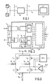
- Fig. 1 shows a portion of an ISDN communication system.
- a line terminating circuit LT which forms part of the central exchange CO is connected to the network terminating circuit NT via a 144 kb/s two-wire full-duplex (e.g. twisted wire) transmission line TL.
- the network terminating circuit NT is located at the subscriber's side and is suitable for connection of a maximum of eight subscriber terminals TE1...TE8.
- the subscriber terminals TE i may be in the form of a telephone set, a facsimile apparatus, a data terminal, an arrangement for processing graphic or picture information, etc.
- the subscriber terminals TE have the disposal of two 64 kb/s circuit-switched channels for speech and data and one 16 kb/s packet or message-switched channels primarily for signalling purposes.
- a connection to the ISDN communication exchange CO is effected via the network terminating circuit NT and the 144kb/s transmission line TL.
- the interface between the subscriber terminals and the network terminating circuit is denoted as the S-interface and is specified in the CCITT recommendation. I.43O.
- the interface between the network terminating circuit NT and the network (the transmission line LT) is denoted as a U-interface in the CCITT recommendation I.43O.
- the S-interface provides a four-wire connection to the subscriber terminals TE1, a 2B+D channel being available for both directions (from and to the subscriber arrangements).
- Each B-channel has a capacity of 64 kb/s.
- the signalling messages required for the two B-channels are transmitted in packet-switched form through the D-channel (16 kb/s).
- Fig. 2 shows a network terminating circuit NT in greater detail.
- the network terminating circuit NT predominantly consists of two parts, namely a U-K and a S-K part.
- the U-K part which is not shown in further detail, constitutes the connecting circuit between the U-interface and the K-interface.
- the K-interface is an interface which is not specified by the CCIT but by the telecommunication industry.
- the S-K part of the network terminating circuit NT accomodates a transmitter XMT and a receiver RCV.
- the receiver RCV detects the signals transmitted by the subscriber terminals TE (Fig. 1) via the receive line RL and conveys them, for example, to the U-K circuit - via the K-interface - for transmission via the transmission line TL.
- AMI-encoded signals are transmitted to the subscriber arrangement by the transmitter XMT via the transmitline SL.
- the transmitter itself is shown in Fig. 3.
- the transmitter includes four switching elements in the form of MOS transistors T1,T2, T3 and T4 incorporated in a (Wheatstone) bridge circuit.
- the gates of the transistors are all connected to a digital control circuit CNTL for (predominantly) causing the switching elements T1, T2, T3 and T4 to conduct or not conduct cross-wise, transmission of a binary "zero". This implies that if transistors T1 and T4 conduct, transistor T2 and T3 are non-conductive and vice versa .
- a binary "one" is transmitted, all transistors T1, T4 are adjusted to the non-conducting state.
- a first transverse branch of the bridge circuit is constituted by the series arrangement between the terminals O1 and O2 of a first resistor R1, a primary winding of transformer Tr (Fig. 2) and a second resistor R2.
- One end of a second transverse branch of the bridge circuit namely terminal O3 is connected to a d.c. voltage source having a fixed potential V DC .
- the second end - terminal O4 - is connected to ground potential via the measuring resistor R m .
- the transmitter includes an operational amplifier OA a first input of which in connected to one side of the measuring resistor R m and to a second input of which a reference potential V ref is applied.
- the differential amplifier OA has the following function. If the bridge circuit is operated, current will flow from the supply terminal O3 to earth via transistor T1 (T3), resistor R1 (R2), the primary winding of transformer Tr, resistor R2 (R1), transistor T4 (T2) and the measuring resistor R m . The voltage across the measuring resistor R m is measured by the differential amplifier OA against the referece voltage V ref . The output voltage of the differential amplifier OA will increase the control voltage for the transistors T3 and T4 or reduce it, causing the output current (that is to say the current through the primary winding) to be influenced. Thus, the output current - within certain limits indepently of the load - will be kept substantially constant.
- the switching slopes of the control signals of the control circuit are very steep.
- a voltage limitation on the supply voltage V DC is provided and a current protection with the aid of the resistors R1 and R2.
- an active limitation is however alternatively possible, it then however being necessary to pay special attention to problems caused by "overshoot" because of the steep slopes.
- the transformer Tr is used of the purpose of electric separation.
- a resistor R3 which has for this object to adjust the input impedance of the transmitter to the value required by CCITT-I.43O is arranged in parallel with the secondary winding (Fig. 2).
- the transistors T1-T4, the control circuit CNTL and the operational amplifier are preferably implemented in one integrated circuit.
- the measuring resistor is kept externally in view of the high absolute and relative accuracy to be imposed on the constancy of the output current.
Landscapes
- Engineering & Computer Science (AREA)
- Computer Networks & Wireless Communication (AREA)
- Signal Processing (AREA)
- Power Engineering (AREA)
- Physics & Mathematics (AREA)
- Spectroscopy & Molecular Physics (AREA)
- Interface Circuits In Exchanges (AREA)
- Bidirectional Digital Transmission (AREA)
- Data Exchanges In Wide-Area Networks (AREA)
Applications Claiming Priority (2)
| Application Number | Priority Date | Filing Date | Title |
|---|---|---|---|
| NL8601331A NL8601331A (nl) | 1986-05-26 | 1986-05-26 | Zender voor isdn s-bus koppelvlakcircuit. |
| NL8601331 | 1986-05-26 |
Publications (2)
| Publication Number | Publication Date |
|---|---|
| EP0247675A1 true EP0247675A1 (de) | 1987-12-02 |
| EP0247675B1 EP0247675B1 (de) | 1993-01-27 |
Family
ID=19848065
Family Applications (1)
| Application Number | Title | Priority Date | Filing Date |
|---|---|---|---|
| EP87200912A Expired - Lifetime EP0247675B1 (de) | 1986-05-26 | 1987-05-15 | Sender für S-Bus-Schnittstelle in einem dienstintegrierenden Digitalnetz (ISDN) |
Country Status (5)
| Country | Link |
|---|---|
| US (1) | US4797904A (de) |
| EP (1) | EP0247675B1 (de) |
| JP (1) | JPS62287793A (de) |
| DE (1) | DE3783803T2 (de) |
| NL (1) | NL8601331A (de) |
Cited By (6)
| Publication number | Priority date | Publication date | Assignee | Title |
|---|---|---|---|---|
| EP0306201A3 (de) * | 1987-08-31 | 1989-09-06 | Advanced Micro Devices, Inc. | Empfänger und dessen Betriebsverfahren |
| EP0428975A3 (de) * | 1989-11-20 | 1992-12-30 | Fujitsu Limited | Treiberschaltung mit konstanter Treibspannung |
| WO1994008398A1 (en) * | 1992-10-07 | 1994-04-14 | Nokia Telecommunications Oy | Line driver circuit |
| EP0724345A1 (de) * | 1995-01-30 | 1996-07-31 | ALCATEL BELL Naamloze Vennootschap | Übertragungsverfahren und Sender mit einem entkoppelten niedrigen Pegel und mit mindestens einem gekoppelten hohen Pegel, Schnittstellenschaltung und Systemkomponente für ein Telekommunikationsnetzwerk, die einen solchen Sender enthalten |
| EP0607677A3 (de) * | 1992-12-22 | 1997-09-03 | Nat Semiconductor Corp | Integrierte Wellenformschaltung. |
| CN100518120C (zh) * | 2007-10-30 | 2009-07-22 | 中国西电电气股份有限公司 | 一种基于can总线的电子式互感器数据传输方法 |
Families Citing this family (14)
| Publication number | Priority date | Publication date | Assignee | Title |
|---|---|---|---|---|
| DE58906842D1 (de) * | 1989-09-28 | 1994-03-10 | Siemens Ag | Schnittstellenbaustein zur Ankopplung modulierter Signale. |
| US4994690A (en) * | 1990-01-29 | 1991-02-19 | Motorola, Inc. | Split level bus |
| JPH03296359A (ja) * | 1990-04-16 | 1991-12-27 | Fujitsu Ltd | Isdnインタフェース回路 |
| US5398249A (en) * | 1992-05-14 | 1995-03-14 | Industrial Technology Research Institute | System for providing simultaneous multiple circuit-switched type communications on an ISDN basic rate interface |
| JPH0677763A (ja) * | 1992-06-17 | 1994-03-18 | Texas Instr Inc <Ti> | 伝送線路を終端する方法と装置 |
| US5461618A (en) * | 1992-06-30 | 1995-10-24 | Industrial Technology Research Institute | Adapter for transmission lines using HDLC frames |
| US5448560A (en) * | 1992-12-23 | 1995-09-05 | Itri | V.110 communication protocol fractional rate adapter for an ISDN network |
| JP3365804B2 (ja) * | 1993-01-12 | 2003-01-14 | 株式会社日立製作所 | 通信回線駆動回路、及びインタフェース用lsi、並びに通信端末装置 |
| US5555263A (en) * | 1994-11-01 | 1996-09-10 | Motorola Inc. | Method and apparatus for reducing switching oscillations in an ISDN line interface circuit |
| DE19630515B4 (de) * | 1996-07-29 | 2004-06-24 | Gude, Michael, Dr. | Interfaceschaltung zur Realisierung einer S/T-Schnittstelle nach Spezifikation ITU I.430 |
| DE19709710C1 (de) * | 1997-03-10 | 1998-10-01 | Siemens Ag | So-Schnittstelle für einen ISDN-Basisanschluß |
| DE19963800C2 (de) * | 1999-12-30 | 2002-11-07 | Siemens Ag | Verfahren und Vorrichtung zur Umsetzung eines bidirektionalen Datenstroms über eine So-Schnittstelle für eine Übermittlung über ein Niederspannungsstromnetz |
| DE19963816C2 (de) * | 1999-12-30 | 2002-09-26 | Siemens Ag | Verfahren und Vorrichtung zur Umsetzung eines bidirektionalen Datenstroms über eine So-Schnittstelle für eine Übermittlung über ein Niederspannungsstromnetz |
| DE102008034109B4 (de) * | 2008-07-21 | 2016-10-13 | Dspace Digital Signal Processing And Control Engineering Gmbh | Schaltung zur Nachbildung einer elektrischen Last |
Citations (5)
| Publication number | Priority date | Publication date | Assignee | Title |
|---|---|---|---|---|
| GB2064918A (en) * | 1979-12-01 | 1981-06-17 | British Aerospace | Data communication systems |
| GB1598679A (en) * | 1977-09-15 | 1981-09-23 | Plessey Co Ltd | Digital data transmission system line driver circuits |
| GB2084827A (en) * | 1980-10-02 | 1982-04-15 | Flowtec Ag | Dc magnetic field generation |
| GB2150368A (en) * | 1983-11-15 | 1985-06-26 | Solex | Fuel injection control apparatus |
| FR2567702A1 (fr) * | 1984-07-13 | 1986-01-17 | France Etat | Emetteur a courant constant pour la transmission de donnees sur une ligne de transmission |
Family Cites Families (3)
| Publication number | Priority date | Publication date | Assignee | Title |
|---|---|---|---|---|
| US4280221A (en) * | 1979-05-31 | 1981-07-21 | The Boeing Company | Digital data communication system |
| US4649548A (en) * | 1981-03-11 | 1987-03-10 | Crane Ronald C | Local computer network transceiver |
| US4606046A (en) * | 1983-12-27 | 1986-08-12 | At&T Bell Laboratories | Converter/line driver circuit for a line repeater |
-
1986
- 1986-05-26 NL NL8601331A patent/NL8601331A/nl not_active Application Discontinuation
-
1987
- 1987-05-15 EP EP87200912A patent/EP0247675B1/de not_active Expired - Lifetime
- 1987-05-15 DE DE8787200912T patent/DE3783803T2/de not_active Expired - Fee Related
- 1987-05-22 US US07/053,231 patent/US4797904A/en not_active Expired - Lifetime
- 1987-05-26 JP JP62127307A patent/JPS62287793A/ja active Pending
Patent Citations (5)
| Publication number | Priority date | Publication date | Assignee | Title |
|---|---|---|---|---|
| GB1598679A (en) * | 1977-09-15 | 1981-09-23 | Plessey Co Ltd | Digital data transmission system line driver circuits |
| GB2064918A (en) * | 1979-12-01 | 1981-06-17 | British Aerospace | Data communication systems |
| GB2084827A (en) * | 1980-10-02 | 1982-04-15 | Flowtec Ag | Dc magnetic field generation |
| GB2150368A (en) * | 1983-11-15 | 1985-06-26 | Solex | Fuel injection control apparatus |
| FR2567702A1 (fr) * | 1984-07-13 | 1986-01-17 | France Etat | Emetteur a courant constant pour la transmission de donnees sur une ligne de transmission |
Non-Patent Citations (2)
| Title |
|---|
| DATA COMMUNICATIONS, vol. 14, no. 11, October 1985, pages 181-184, New York, US; J. PARKER et al.: "Bipolar and MOS make the best of all possible network worlds" * |
| ELECTRONIC DESIGN, vol. 32, no. 25, December 1984, pages 157-162,164,166,168,170, Waseca, US; A. CLARK: "Controller chips pair up in S interface for ISDN systems" * |
Cited By (11)
| Publication number | Priority date | Publication date | Assignee | Title |
|---|---|---|---|---|
| EP0306201A3 (de) * | 1987-08-31 | 1989-09-06 | Advanced Micro Devices, Inc. | Empfänger und dessen Betriebsverfahren |
| EP0428975A3 (de) * | 1989-11-20 | 1992-12-30 | Fujitsu Limited | Treiberschaltung mit konstanter Treibspannung |
| US5517066A (en) * | 1989-11-20 | 1996-05-14 | Fujitsu Limited | Constant voltage drive type driver circuit |
| WO1994008398A1 (en) * | 1992-10-07 | 1994-04-14 | Nokia Telecommunications Oy | Line driver circuit |
| GB2287145A (en) * | 1992-10-07 | 1995-09-06 | Nokia Telecommunications Oy | Line driver circuit |
| GB2287145B (en) * | 1992-10-07 | 1997-03-26 | Nokia Telecommunications Oy | Line driver circuit |
| EP0607677A3 (de) * | 1992-12-22 | 1997-09-03 | Nat Semiconductor Corp | Integrierte Wellenformschaltung. |
| EP0724345A1 (de) * | 1995-01-30 | 1996-07-31 | ALCATEL BELL Naamloze Vennootschap | Übertragungsverfahren und Sender mit einem entkoppelten niedrigen Pegel und mit mindestens einem gekoppelten hohen Pegel, Schnittstellenschaltung und Systemkomponente für ein Telekommunikationsnetzwerk, die einen solchen Sender enthalten |
| US5787120A (en) * | 1995-01-30 | 1998-07-28 | Alcatel N.V. | Transmission method and transmitter for signals with a decoupled low level and at least one coupled high level for a telecommunication network including such a transmitter |
| AU707018B2 (en) * | 1995-01-30 | 1999-07-01 | Alcatel N.V. | A transmission method |
| CN100518120C (zh) * | 2007-10-30 | 2009-07-22 | 中国西电电气股份有限公司 | 一种基于can总线的电子式互感器数据传输方法 |
Also Published As
| Publication number | Publication date |
|---|---|
| JPS62287793A (ja) | 1987-12-14 |
| DE3783803D1 (de) | 1993-03-11 |
| DE3783803T2 (de) | 1993-08-12 |
| NL8601331A (nl) | 1987-12-16 |
| EP0247675B1 (de) | 1993-01-27 |
| US4797904A (en) | 1989-01-10 |
Similar Documents
| Publication | Publication Date | Title |
|---|---|---|
| EP0247675B1 (de) | Sender für S-Bus-Schnittstelle in einem dienstintegrierenden Digitalnetz (ISDN) | |
| US4449218A (en) | Analog/digital telecommunication subscriber station | |
| US4173714A (en) | Communication circuit with combined power feed and data transmission over a phantom channel | |
| US5208846A (en) | Subscriber loop tester for telephone switching systems | |
| US4685129A (en) | Power transmission arrangement for telecommunications systems | |
| US4759059A (en) | Analog telephone circuit for digital telephone system | |
| US5305377A (en) | Apparatus for providing an ISDN to analog interface | |
| RU2127957C1 (ru) | Система передачи информации | |
| US4232293A (en) | Line interface unit for voice and wide band signal coupling | |
| US5341418A (en) | ISDN terminal adapter for access from analog signal equipment of four-wire full duplex type to ISDN | |
| AU627982B2 (en) | A new key telephone interface | |
| EP0835580B1 (de) | Datenzugriffsanordnung | |
| US4378472A (en) | Two to four wire hybrid circuit arrangement for a pulse code modulated time multiplex telecommunication system | |
| US4418249A (en) | Four-wire terminating circuit | |
| KR100360576B1 (ko) | 데이터 최적화된 코덱 | |
| US6661894B1 (en) | Circuit configuration and chip set for supplying a telephone subscriber loop with a supply voltage and network-side terminal of a telephone subscriber loop | |
| US4554416A (en) | Low voltage two wire to four wire telephone circuit converter apparatus | |
| US5177735A (en) | Private telephone installation architecture | |
| KR930006551B1 (ko) | 교환시스팀의 애널로그 입중계 회로장치 | |
| KR100336512B1 (ko) | 간이 사설교환기의 내장형 네트워크 단말 장치 | |
| EP0583511A1 (de) | Hausinternes Nachrichtenkommunikationsverfahren über einem S-Bus eines ISDN-Netzes | |
| JPH08251819A (ja) | 給電装置 | |
| Van Simaeys et al. | An ISDN S-Interface Transceiver for Public and Private Digital Loops | |
| GB2293942A (en) | Digital key telephone system | |
| Lu et al. | The realization of ISDN user-network interface S0 reference point with special VLSI |
Legal Events
| Date | Code | Title | Description |
|---|---|---|---|
| PUAI | Public reference made under article 153(3) epc to a published international application that has entered the european phase |
Free format text: ORIGINAL CODE: 0009012 |
|
| AK | Designated contracting states |
Kind code of ref document: A1 Designated state(s): DE FR GB NL SE |
|
| 17P | Request for examination filed |
Effective date: 19880526 |
|
| 17Q | First examination report despatched |
Effective date: 19900809 |
|
| RAP1 | Party data changed (applicant data changed or rights of an application transferred) |
Owner name: AT&T NETWORK SYSTEMS INTERNATIONAL B.V. Owner name: APT NEDERLAND B.V. |
|
| RAP3 | Party data changed (applicant data changed or rights of an application transferred) |
Owner name: AT&T NETWORK SYSTEMS INTERNATIONAL B.V. Owner name: AT&T NETWORK SYSTEMS NEDERLAND B.V. |
|
| GRAA | (expected) grant |
Free format text: ORIGINAL CODE: 0009210 |
|
| AK | Designated contracting states |
Kind code of ref document: B1 Designated state(s): DE FR GB NL SE |
|
| REF | Corresponds to: |
Ref document number: 3783803 Country of ref document: DE Date of ref document: 19930311 |
|
| ET | Fr: translation filed | ||
| PLBE | No opposition filed within time limit |
Free format text: ORIGINAL CODE: 0009261 |
|
| STAA | Information on the status of an ep patent application or granted ep patent |
Free format text: STATUS: NO OPPOSITION FILED WITHIN TIME LIMIT |
|
| 26N | No opposition filed | ||
| EAL | Se: european patent in force in sweden |
Ref document number: 87200912.1 |
|
| PGFP | Annual fee paid to national office [announced via postgrant information from national office to epo] |
Ref country code: GB Payment date: 19960313 Year of fee payment: 10 |
|
| PGFP | Annual fee paid to national office [announced via postgrant information from national office to epo] |
Ref country code: DE Payment date: 19960319 Year of fee payment: 10 |
|
| PGFP | Annual fee paid to national office [announced via postgrant information from national office to epo] |
Ref country code: SE Payment date: 19960402 Year of fee payment: 10 |
|
| PGFP | Annual fee paid to national office [announced via postgrant information from national office to epo] |
Ref country code: FR Payment date: 19960404 Year of fee payment: 10 |
|
| PGFP | Annual fee paid to national office [announced via postgrant information from national office to epo] |
Ref country code: NL Payment date: 19960531 Year of fee payment: 10 |
|
| PG25 | Lapsed in a contracting state [announced via postgrant information from national office to epo] |
Ref country code: GB Effective date: 19970515 |
|
| PG25 | Lapsed in a contracting state [announced via postgrant information from national office to epo] |
Ref country code: SE Effective date: 19970516 |
|
| PG25 | Lapsed in a contracting state [announced via postgrant information from national office to epo] |
Ref country code: NL Effective date: 19971201 |
|
| GBPC | Gb: european patent ceased through non-payment of renewal fee |
Effective date: 19970515 |
|
| PG25 | Lapsed in a contracting state [announced via postgrant information from national office to epo] |
Ref country code: FR Free format text: LAPSE BECAUSE OF NON-PAYMENT OF DUE FEES Effective date: 19980130 |
|
| EUG | Se: european patent has lapsed |
Ref document number: 87200912.1 |
|
| NLV4 | Nl: lapsed or anulled due to non-payment of the annual fee |
Effective date: 19971201 |
|
| PG25 | Lapsed in a contracting state [announced via postgrant information from national office to epo] |
Ref country code: DE Free format text: LAPSE BECAUSE OF NON-PAYMENT OF DUE FEES Effective date: 19980203 |
|
| REG | Reference to a national code |
Ref country code: FR Ref legal event code: ST |