EP0247645B1 - Closure for a container with a pouring opening closed by a membrane fixed by induction or conduction - Google Patents
Closure for a container with a pouring opening closed by a membrane fixed by induction or conduction Download PDFInfo
- Publication number
- EP0247645B1 EP0247645B1 EP87200541A EP87200541A EP0247645B1 EP 0247645 B1 EP0247645 B1 EP 0247645B1 EP 87200541 A EP87200541 A EP 87200541A EP 87200541 A EP87200541 A EP 87200541A EP 0247645 B1 EP0247645 B1 EP 0247645B1
- Authority
- EP
- European Patent Office
- Prior art keywords
- container
- cap
- cover
- orifice
- induction
- Prior art date
- Legal status (The legal status is an assumption and is not a legal conclusion. Google has not performed a legal analysis and makes no representation as to the accuracy of the status listed.)
- Expired - Lifetime
Links
- 230000006698 induction Effects 0.000 title claims abstract description 7
- 239000012528 membrane Substances 0.000 title 1
- 238000000034 method Methods 0.000 claims description 2
- 238000007789 sealing Methods 0.000 claims 1
- 238000005520 cutting process Methods 0.000 abstract description 10
- 239000003292 glue Substances 0.000 description 2
- 230000000994 depressogenic effect Effects 0.000 description 1
- 238000003780 insertion Methods 0.000 description 1
- 230000037431 insertion Effects 0.000 description 1
- 230000000717 retained effect Effects 0.000 description 1
Images

Classifications
-
- B—PERFORMING OPERATIONS; TRANSPORTING
- B65—CONVEYING; PACKING; STORING; HANDLING THIN OR FILAMENTARY MATERIAL
- B65D—CONTAINERS FOR STORAGE OR TRANSPORT OF ARTICLES OR MATERIALS, e.g. BAGS, BARRELS, BOTTLES, BOXES, CANS, CARTONS, CRATES, DRUMS, JARS, TANKS, HOPPERS, FORWARDING CONTAINERS; ACCESSORIES, CLOSURES, OR FITTINGS THEREFOR; PACKAGING ELEMENTS; PACKAGES
- B65D51/00—Closures not otherwise provided for
- B65D51/18—Arrangements of closures with protective outer cap-like covers or of two or more co-operating closures
- B65D51/20—Caps, lids, or covers co-operating with an inner closure arranged to be opened by piercing, cutting, or tearing
- B65D51/22—Caps, lids, or covers co-operating with an inner closure arranged to be opened by piercing, cutting, or tearing having means for piercing, cutting, or tearing the inner closure
- B65D51/221—Caps, lids, or covers co-operating with an inner closure arranged to be opened by piercing, cutting, or tearing having means for piercing, cutting, or tearing the inner closure a major part of the inner closure being left inside the container after the opening
- B65D51/222—Caps, lids, or covers co-operating with an inner closure arranged to be opened by piercing, cutting, or tearing having means for piercing, cutting, or tearing the inner closure a major part of the inner closure being left inside the container after the opening the piercing or cutting means being integral with, or fixedly attached to, the outer closure
- B65D51/225—Caps, lids, or covers co-operating with an inner closure arranged to be opened by piercing, cutting, or tearing having means for piercing, cutting, or tearing the inner closure a major part of the inner closure being left inside the container after the opening the piercing or cutting means being integral with, or fixedly attached to, the outer closure and further comprising a device first inhibiting displacement of the outer closure
-
- B—PERFORMING OPERATIONS; TRANSPORTING
- B65—CONVEYING; PACKING; STORING; HANDLING THIN OR FILAMENTARY MATERIAL
- B65D—CONTAINERS FOR STORAGE OR TRANSPORT OF ARTICLES OR MATERIALS, e.g. BAGS, BARRELS, BOTTLES, BOXES, CANS, CARTONS, CRATES, DRUMS, JARS, TANKS, HOPPERS, FORWARDING CONTAINERS; ACCESSORIES, CLOSURES, OR FITTINGS THEREFOR; PACKAGING ELEMENTS; PACKAGES
- B65D2251/00—Details relating to container closures
- B65D2251/0003—Two or more closures
- B65D2251/0006—Upper closure
- B65D2251/0015—Upper closure of the 41-type
-
- B—PERFORMING OPERATIONS; TRANSPORTING
- B65—CONVEYING; PACKING; STORING; HANDLING THIN OR FILAMENTARY MATERIAL
- B65D—CONTAINERS FOR STORAGE OR TRANSPORT OF ARTICLES OR MATERIALS, e.g. BAGS, BARRELS, BOTTLES, BOXES, CANS, CARTONS, CRATES, DRUMS, JARS, TANKS, HOPPERS, FORWARDING CONTAINERS; ACCESSORIES, CLOSURES, OR FITTINGS THEREFOR; PACKAGING ELEMENTS; PACKAGES
- B65D2251/00—Details relating to container closures
- B65D2251/0003—Two or more closures
- B65D2251/0068—Lower closure
- B65D2251/0093—Membrane
Definitions
- This invention relates to a stopper intended for closing by "clipping" a container, the orifice of which is closed by a cover secured to it by induction or conduction comprising, on the directed side, in the position of use, towards the 'aforementioned cover, a circular knife for cutting the cover when the cap is pressed into the container and the cap having projections for clipping, said positioning and use.
- the object of the invention is to produce a stopper which has, at the same time, the characteristics of a tamper-evident stopper which, moreover, allows the cutting of a heat-sealable seal secured to the orifice of the container by induction or conduction.
- the knife does not cause a perfectly circular cutting of the cover. At one point of this cover it is not cut but remains attached to the edge of the seal sealed on the orifice of the container. Due to the pressure exerted on it during the cutting operation and due to its weight, the cut part hangs down. It is neither practical nor hygienic to let this cut part hang inside the container. If you want to prevent contact with the products contained therein, you must remove this cut part, either by hand or using a utensil.
- the object of the invention is to remedy this drawback by proposing a stopper which allows a perfectly circular cutting of the cover while preventing it from falling into the contents of the container.
- the aforementioned cover is secured, in its center, to the aforementioned plug.
- the aforementioned knife has an arched sawtooth profile.
- Figure 1 is a sectional view of the cap according to the invention closing by clipping the orifice of a container provided with a heat sealable seal secured by induction from the orifice of the container.
- Figure 2 is a deployed view of a portion of the knife which is provided with the plug according to the invention.
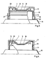
- Figure 3 is a sectional view of a plug closing by clipping the orifice of a container provided with a heat-sealable cap secured by conduction of the orifice of the container.
- Figure 4 is a sectional view of the cap according to the invention shown in its depressed position relative to the orifice of the container.
- FIGS. 1 and 3 show the two methods of joining a cover on the orifice 2 of a container 3. It is intended here by orifice, the end of the neck of a bottle. It is understood that any other arrangement of the orifice relative to the bottle and any other profile of the bottle are within the scope of this patent application.
- the cover 1 is secured by application of heat by induction of the orifice 2.
- the cover 1 is secured to the plug 4 by a point of glue 5.
- An internal projection 6 is provided inside the cylindrical part 4 'of the plug 4.
- the seal 1 is applied to the upper edge of the orifice 2 by the shoulder 4 "of the plug 4. This results from the need to provide a space above the orifice 2 to pass to what is known as the opening notch. This support is achieved by the presence of the shoulder 4 ".
- cylindrical part 4 'of the plug 4 has an internal projection 6 which cooperates with an external projection 7, called positioning or an external projection 8, called use.
- the external projection 7 called the positioning projection, maintains the plug in the position in which the assembly is shown in FIG. 1.
- the external projection 8 maintains the plug pr relative to the container in the so-called use position.
- a tearable ring 9 provided with a gripping or tearing tab 10, which prevents the plug from being inserted into the orifice of the container which therefore also constitutes a witness indicating that the stopper or closure has not been breached.
- a circular knife 11 which, as long as the tear-off ring 9 has not been separated, must not come into contact with the cover 1.
- the user can insert the plug 4, the circular knife 11 of which will cut the cover 1.
- the circular knife 11 has saw teeth arched 12 which are visible in the partial view deployed according to FIG. 2.
- the external diameter of the circular knife 11 corresponds substantially to the internal diameter of the orifice 2 of the container 3.
- FIG. 3 A stopper made according to the same principle is re presented in Figure 3 where we note that the cover 1 has been secured by conduction on the projection 13 defining the orifice of the neck 14 of the container 15.
- the neck of the container has a second external projection 16, while the part cylindrical 17 of the plug 18 has an internal projection 19 which is grasped between the external projections 13 and 16 when the plug 18 is in the position shown in FIG. 3, the tearing ring 20, provided with a tearing tab 21, having not yet been separated from the cap.
- the plug 18 according to FIG. 3, joined by a point of glue 5 of the cover 1 also has, like the plug 4 of FIG. 1, an internal knife 22 which can cut the cover 1 when the plug 18 is pushed in. in the orifice of the container 15 after tearing off the ring 20.
- the circular knife 22 has, like the circular knife 11, the same arcuate teeth 12 so that the insertion of the plug 18 into the container 15 causes, without particular effort, the cutting of the cover 1.
- FIG. 4 shows the plug 18 pressed into the neck 14 of the container 15.
- the outside diameter of the circular knife 22 is substantially equal to the inside diameter of the orifice of the container, so that when the cap has been pushed in and the cover cut out , the outer surface of the circular knife 1 forms a lip for filling the orifice of the container.
Landscapes
- Engineering & Computer Science (AREA)
- Mechanical Engineering (AREA)
- Closures For Containers (AREA)
- Medical Preparation Storing Or Oral Administration Devices (AREA)
Abstract
Description
Cette invention concerne un bouchon destiné à l'obturation par «clipsage» d'un récipient, dont l'orifice est obturé par un opercule solidarisé de celui-ci par induction ou conduction comportant du côté dirigé, en position d'utilisation, vers l'opercule précité, un couteau circulaire destiné à découper l'opercule lorsque le bouchon est enfoncé dans le récipient et le bouchon présentant des saillies servant au clipsage, dit de positionnement et d'utilisation.This invention relates to a stopper intended for closing by "clipping" a container, the orifice of which is closed by a cover secured to it by induction or conduction comprising, on the directed side, in the position of use, towards the 'aforementioned cover, a circular knife for cutting the cover when the cap is pressed into the container and the cap having projections for clipping, said positioning and use.
Le but de l'invention est de réaliser un bouchon qui a, à la fois, les caractéristiques d'un bouchon inviolable qui, de plus, permet la découpe d'un opercule thermoscellable solidarisé de l'orifice du récipient par induction ou conduction.The object of the invention is to produce a stopper which has, at the same time, the characteristics of a tamper-evident stopper which, moreover, allows the cutting of a heat-sealable seal secured to the orifice of the container by induction or conduction.
Il a déjà été proposé de prévoir un couteau circulaire sur la face interne d'un couvercle afin de découper dans l'opercule scellé sur l'orifice du récipient une ouverture par laquelle les produits contenus dans le récipient peuvent être atteints. Un exemple d'un tel récipient et de son bouchon est donné par le brevet britannique 2 127 387.It has already been proposed to provide a circular knife on the internal face of a cover in order to cut in the seal sealed on the orifice of the container an opening through which the products contained in the container can be reached. An example of such a container and its cap is given by British Patent 2,127,387.
Selon ce brevet, le couteau ne provoque pas une découpe parfaitement circulaire de l'opercule. En un point de cet opercule celui-ci n'est pas découpé mais demeure attaché au bord de l'opercule scellé sur l'orifice du récipient. Du fait de la pression exercée sur celui-ci lors de l'opération de découpage et en raison de son poids, la partie découpée pend vers le bas. Il n'est ni pratique, ni hygiénique de laisser cette partie découpée pendre à l'intérieur du récipient. Si on veut empêcher tout contact avec les produits contenus dans celui-ci, il faut écarter cette partie découpée, soit à la main, soit à l'aide d'un ustensile.According to this patent, the knife does not cause a perfectly circular cutting of the cover. At one point of this cover it is not cut but remains attached to the edge of the seal sealed on the orifice of the container. Due to the pressure exerted on it during the cutting operation and due to its weight, the cut part hangs down. It is neither practical nor hygienic to let this cut part hang inside the container. If you want to prevent contact with the products contained therein, you must remove this cut part, either by hand or using a utensil.
Au cours de cette manipulation, la découpe de l'opercule tombe fréquemment dans le récipient, ce qui constitue un désavantage de plus d'un tel moyen . de découpage.During this manipulation, the cutting of the lid frequently falls into the container, which constitutes a disadvantage of more than one such means. cutting.
L'invention a pour but de remédier à cet inconvénient en proposant un bouchon qui permet une découpe parfaitement circulaire de l'opercule tout en empêchant sa chute dans le contenu du récipient.The object of the invention is to remedy this drawback by proposing a stopper which allows a perfectly circular cutting of the cover while preventing it from falling into the contents of the container.
Pour réaliser cet objectif conformément à l'invention, l'opercule précité est solidarisé, en son centre, du bouchon précité.To achieve this objective in accordance with the invention, the aforementioned cover is secured, in its center, to the aforementioned plug.
Selon un mode de réalisation préféré de l'invention, le couteau précité présente un profil en dents de scie arquées.According to a preferred embodiment of the invention, the aforementioned knife has an arched sawtooth profile.
D'autres détails et avantages ressortiront de la description qui sera donnée ci-après d'un bouchon destiné à l'obturation par clipsage d'un récipient dont l'orifice est obturé par un opercule thermoscellable, selon l'invention. Cette description n'est donnée qu'à titre d'exemple et ne limite pas l'invention. Les notations de référence se rapportent aux figures ci-jointes.Other details and advantages will emerge from the description which will be given below of a stopper intended for closing by clipping a container, the orifice of which is closed by a heat-sealable cap, according to the invention. This description is given by way of example only and does not limit the invention. The reference notations refer to the attached figures.
La figure 1 est une vue en coupe du bouchon selon l'invention obturant par clipsage l'orifice d'un récipient muni d'un opercule thermoscellable solidarisé par induction de l'orifice du récipient.Figure 1 is a sectional view of the cap according to the invention closing by clipping the orifice of a container provided with a heat sealable seal secured by induction from the orifice of the container.
La figure 2 est une vue déployée d'une partie du couteau dont est muni le bouchon selon l'invention.Figure 2 is a deployed view of a portion of the knife which is provided with the plug according to the invention.
La figure 3 est une vue en coupe d'un bouchon obturant par clipsage l'orifice d'un récipient muni d'un opercule thermoscellable solidarisé par conduction de l'orifice du récipient.Figure 3 is a sectional view of a plug closing by clipping the orifice of a container provided with a heat-sealable cap secured by conduction of the orifice of the container.
La figure 4 est une vue en coupe du bouchon selon l'invention représenté dans sa position enfoncée par rapport à l'orifice du récipient.Figure 4 is a sectional view of the cap according to the invention shown in its depressed position relative to the orifice of the container.
Avant d'entamer la description détaillée du bouchon selon l'invention, il sera renvoyé aux figures 1 et 3, qui font apparaître les deux procédés de soli- darisation d'un opercule sur l'orifice 2 d'un récipient 3. On entend ici par orifice, l'extrémité du col d'un flacon. Il est entendu que toute autre disposition de l'orifice par rapport au flacon et tout autre profil du flacon rentrent dans le cadre de la présente demande de brevet.Before starting the detailed description of the stopper according to the invention, reference will be made to FIGS. 1 and 3, which show the two methods of joining a cover on the
Selon la figure 1, l'opercule 1 est solidarisé par application de chaleur par induction de l'orifice 2. L'opercule 1 est solidarisé du bouchon 4 par un point de colle 5. Une saillie interne 6 est prévue à l'intérieur de la partie cylindrique 4' du bouchon 4. L'opercule à sceller 1 est appliqué sur le bord supérieur de l'orifice 2 par l'épaulement 4" du bouchon 4. Ceci résulte de la nécessité de réaliser un espace au-dessus de l'orifice 2 pour passer à ce qu'il est convenu d'appeler le cran d'ouverture. Cet appui est réalisé par la présence de l'épaulement 4".According to FIG. 1, the
De plus la partie cylindrique 4' du bouchon 4 présente une saillie interne 6 qui coopère avec une saillie externe 7, dite de positionnement ou une saillie externe 8, dite d'utilisation.In addition the cylindrical part 4 'of the
La saillie externe 7, dite de positionnement, maintient le bouchon dans la position dans laquelle l'ensemble est représenté à la figure 1.The external projection 7, called the positioning projection, maintains the plug in the position in which the assembly is shown in FIG. 1.
La saillie externe 8 maintient le bouchon pr rapport au récipient dans la position dite d'utilisation.The external projection 8 maintains the plug pr relative to the container in the so-called use position.
A la base de la partie cylindrique 4' est prévue une bague déchirable 9, munie d'une languette de préhension ou d'arrachage 10, qui empêche que le bouchon soit enfoncé dans l'orifice du récipient qui constitue donc également un temoin indiquant que le bouchon ou la fermeture n'a pas été violé.At the base of the
A la partie inférieure du bouchon 4 est prévu un couteau circulaire 11 qui, aussi longtemps que la bague déchirable 9 n'a pas été écartée, ne doit pas entrer en contact avec l'opercule 1.At the lower part of the
Lorsque la bague déchirable 9 a été arrachée, l'utilisateur peut enfoncer le bouchon 4 dont le couteau circulaire 11 va découper l'opercule 1. Pour que cette découpe se fasse aisément et sans effort exagéré, le couteau circulaire 11 présente des dents de scie arquées 12 qui sont visibles à la vue partielle déployée selon la figure 2.When the tearable ring 9 has been torn off, the user can insert the
Lorsque le couvercle 4 a été enfoncé et l'opercule 1 découpé, la saillie externe 7 est passée au-delà de la saillie interne 6 et le bouchon est alors retenu grâce à la coopération entre la saillie externe 8 et la saillie interne 6.When the
Le diamètre externe du couteau circulaire 11 correspond sensiblement au diamètre interne de l'orifice 2 du récipient 3.The external diameter of the
Un bouchon réalisé selon le même principe est représenté à la figure 3 où l'on remarque que l'opercule 1 a été solidarisé par conduction sur la saillie 13 délimitant l'orifice du col 14 du récipient 15. Le col du récipient présente une seconde saillie externe 16, tandis que la partie cylindrique 17 du bouchon 18 présente une saillie interne 19 qui est saisie entre les saillies externes 13 et 16 lorsque le bouchon 18 se trouve dans la position représentée à la figure 3, la bague d'arrachage 20, munie d'une languette d'arrachage 21, n'ayant pas encore été séparée du bouchon.A stopper made according to the same principle is re presented in Figure 3 where we note that the
Le bouchon 18 selon la figure 3, solidarisé par un point de colle 5 de l'opercule 1 présente également, comme le bouchon 4 de la figure 1, un couteau interne 22 qui peut découper l'opercule 1 lorsqu'on enfonce le bouchon 18 dans l'orifice du récipient 15 après arrachage de la bague 20.The
Le couteau circulaire 22 présente, tout comme le couteau circulaire 11, les mêmes dents arquées 12 afin que l'enfoncement du bouchon 18 dans le récipient 15 provoque, sans effort particulier, la découpe de l'opercule 1.The
La figure 4 montre le bouchon 18 enfoncé dans le col 14 du récipient 15.FIG. 4 shows the
Dans les formes d'exécution selon les figures 1, 3 ou 4, le diamètre extérieur du couteau circulaire 22 est sensiblement égal au diamètre intérieur de l'orifice du récipient, de telle sorte que lorsque le bouchon a été enfoncé et l'opercule découpé, la surface extérieure du couteau circulaire 1 forme lèvre de rebouchage de l'orifice du récipient.In the embodiments according to Figures 1, 3 or 4, the outside diameter of the
Claims (3)
Priority Applications (1)
| Application Number | Priority Date | Filing Date | Title |
|---|---|---|---|
| AT87200541T ATE53364T1 (en) | 1986-05-30 | 1987-03-25 | CLOSURE FOR A CONTAINER WHICH PORT IS CLOSED BY A MEMBRANE FIXED BY INDUCTION OR CONDUCTION. |
Applications Claiming Priority (2)
| Application Number | Priority Date | Filing Date | Title |
|---|---|---|---|
| BE0/216725A BE904849A (en) | 1986-05-30 | 1986-05-30 | PLUG FOR SEALING A CONTAINER, THE PORT OF WHICH IS CLOSED BY A SOLIDARIZED LID THEREOF BY INDUCTION OR CONDUCTION. |
| BE216725 | 1986-05-30 |
Publications (2)
| Publication Number | Publication Date |
|---|---|
| EP0247645A1 EP0247645A1 (en) | 1987-12-02 |
| EP0247645B1 true EP0247645B1 (en) | 1990-06-06 |
Family
ID=3844039
Family Applications (1)
| Application Number | Title | Priority Date | Filing Date |
|---|---|---|---|
| EP87200541A Expired - Lifetime EP0247645B1 (en) | 1986-05-30 | 1987-03-25 | Closure for a container with a pouring opening closed by a membrane fixed by induction or conduction |
Country Status (7)
| Country | Link |
|---|---|
| US (1) | US4754889A (en) |
| EP (1) | EP0247645B1 (en) |
| AT (1) | ATE53364T1 (en) |
| BE (1) | BE904849A (en) |
| CA (1) | CA1288385C (en) |
| DE (1) | DE3763054D1 (en) |
| ES (1) | ES2015041B3 (en) |
Families Citing this family (30)
| Publication number | Priority date | Publication date | Assignee | Title |
|---|---|---|---|---|
| DE8703422U1 (en) * | 1987-03-06 | 1987-04-16 | Pharma-Metall GmbH, 5190 Stolberg | Closure for a container, preferably for pharmaceutical containers |
| BE1000760A6 (en) * | 1987-07-27 | 1989-03-28 | Lynes Holding Sa | POURING CAP DEVICE. |
| US4867326A (en) * | 1988-08-25 | 1989-09-19 | Cp Packaging | Child resistant cap and tube assembly |
| US4884703A (en) * | 1988-09-27 | 1989-12-05 | Cp Packaging Inc. | Container and closure assembly |
| US5125522A (en) * | 1988-12-22 | 1992-06-30 | Abbott Laboratories | Enteral delivery set assembly |
| US5082136A (en) * | 1991-02-06 | 1992-01-21 | Enviro-Packaging Corp. | Container and cap construction |
| SE9100921L (en) * | 1991-03-27 | 1992-09-28 | Tetra Alfa Holdings | OPENING DEVICE FOR A PACKAGING CONTAINER AND WAY TO MANUFACTURE THEM |
| SE468893B (en) * | 1991-09-04 | 1993-04-05 | Tetra Alfa Holdings | OPENING DEVICE FOR PACKAGING CONTAINERS |
| SE469025B (en) * | 1991-09-04 | 1993-05-03 | Tetra Alfa Holdings | OPENING DEVICE FOR A PACKAGING CONTAINER |
| KR950004515Y1 (en) * | 1992-08-13 | 1995-06-07 | 이용학 | Cap for injection |
| KR0119874Y1 (en) * | 1993-03-02 | 1998-06-01 | 이용학 | Synthetic resin sealing cap for a fluid bottle |
| US5477972A (en) * | 1994-06-02 | 1995-12-26 | Lester; William M. | Tamper evident closure device for bottles and the like |
| US5806699A (en) * | 1996-12-06 | 1998-09-15 | Ekkert; Len | Closure vent arrangement and forming method therefor |
| US6024234A (en) * | 1998-11-09 | 2000-02-15 | Abbott Laboratories | Closure device for a membrane sealed container |
| MXPA03003851A (en) * | 2000-11-02 | 2003-07-28 | Spreckelsen Mcgeough Ltd | Resealable gas impermeable sealing assembly. |
| DE20110807U1 (en) | 2001-06-29 | 2001-09-13 | Wella Ag, 64295 Darmstadt | Containers with tamper evidence |
| UA82868C2 (en) * | 2003-02-14 | 2008-05-26 | Closure | |
| US20050167430A1 (en) * | 2004-02-03 | 2005-08-04 | Sonoco Development, Inc. | Double rib overcap for a container with a removable membrane |
| DE102004027734A1 (en) | 2004-06-07 | 2005-12-22 | Filtertek B.V., Newcastle West | Device for connecting a ventilator with the patient |
| US7673653B2 (en) | 2004-06-17 | 2010-03-09 | Filtertek Inc. | Check valve |
| DE102004032100B4 (en) * | 2004-07-01 | 2006-06-22 | Rainer Ammann | Method for detaching or separating a sealing film and screw caps sealed onto the edge of the neck of a bottle or the like to carry out these methods |
| DE202005010459U1 (en) * | 2004-11-22 | 2005-10-13 | Filtertek B.V., Newcastle West | Device for introducing air into containers used in artificial nutrition |
| EA010357B1 (en) * | 2004-12-09 | 2008-08-29 | Хее Квон Рхо | Vessel cap and system for manufacturing the same |
| KR100655892B1 (en) * | 2005-11-18 | 2006-12-11 | 노희권 | Container stopper and its manufacturing process |
| US8328036B2 (en) | 2006-05-08 | 2012-12-11 | Sonoco Development, Inc. | Double rib overcap with plug for a container with a removable membrane |
| US20070262077A1 (en) * | 2006-05-11 | 2007-11-15 | Sonoco Development, Inc. | Dual function overcap for a container with a removable membrane |
| WO2008103343A1 (en) * | 2007-02-23 | 2008-08-28 | Sonoco Development, Inc. | Hinged overcap from a container |
| US8746476B1 (en) * | 2009-02-13 | 2014-06-10 | Berlin Packaging, Llc | Closure having a seal piercing unit |
| GB0907662D0 (en) * | 2009-05-02 | 2009-06-10 | Elopak Systems | Improvements in or relating to pour spout fitments |
| EP2496489A4 (en) * | 2009-11-05 | 2013-04-17 | Liquid Health Labs Inc | UNIVERSAL BOMB CLOSURE TO DISTRIBUTE A DOSE |
Family Cites Families (8)
| Publication number | Priority date | Publication date | Assignee | Title |
|---|---|---|---|---|
| US2066390A (en) * | 1934-07-13 | 1937-01-05 | Armstrong Cork Co | Closure for containers |
| CH318365A (en) * | 1953-03-09 | 1956-12-31 | Perfectube Societe Anonyme Coo | Cutter for sealed orifice |
| FR83084E (en) * | 1962-02-17 | 1964-06-05 | Crushable packaging tube for pasty products | |
| FR1322352A (en) * | 1962-02-17 | 1963-03-29 | Crushable packaging tube for pasty products | |
| FR1416483A (en) * | 1964-09-22 | 1965-11-05 | Telescopic shutters forming plugs | |
| US3402855A (en) * | 1967-05-16 | 1968-09-24 | Gillette Co | Mixing container |
| FR2049485A5 (en) * | 1969-06-11 | 1971-03-26 | Tard Francois | |
| AU1859383A (en) * | 1982-09-30 | 1984-04-05 | Sunbeam Plastics Corp. | Tamper indicating dispenser |
-
1986
- 1986-05-30 BE BE0/216725A patent/BE904849A/en not_active IP Right Cessation
-
1987
- 1987-03-25 EP EP87200541A patent/EP0247645B1/en not_active Expired - Lifetime
- 1987-03-25 DE DE8787200541T patent/DE3763054D1/en not_active Expired - Lifetime
- 1987-03-25 AT AT87200541T patent/ATE53364T1/en not_active IP Right Cessation
- 1987-03-25 ES ES87200541T patent/ES2015041B3/en not_active Expired - Lifetime
- 1987-04-14 CA CA000534617A patent/CA1288385C/en not_active Expired - Fee Related
- 1987-04-15 US US07/038,751 patent/US4754889A/en not_active Expired - Lifetime
Also Published As
| Publication number | Publication date |
|---|---|
| CA1288385C (en) | 1991-09-03 |
| ATE53364T1 (en) | 1990-06-15 |
| EP0247645A1 (en) | 1987-12-02 |
| ES2015041B3 (en) | 1990-08-01 |
| US4754889A (en) | 1988-07-05 |
| BE904849A (en) | 1986-09-15 |
| DE3763054D1 (en) | 1990-07-12 |
Similar Documents
| Publication | Publication Date | Title |
|---|---|---|
| EP0247645B1 (en) | Closure for a container with a pouring opening closed by a membrane fixed by induction or conduction | |
| CA2057889C (en) | Pourer for bottles and such containers with a borer element to perforate container pouring spout lid | |
| EP0304972B1 (en) | Closure with a pouring device | |
| EP0270134B1 (en) | Pouring closure | |
| EP0268538A1 (en) | Cap for a container, initially closed by a pierceable membrane | |
| EP0475789A1 (en) | Device to store separately at least two products and to mix them at the time of first use | |
| EP0293290A1 (en) | Closure device for containers | |
| FR2928351A1 (en) | DEVICE FOR CLOSING A RECIPIENT COLLAR. | |
| EP0358583B1 (en) | Tamper-proof closure means for containers | |
| FR2765194A1 (en) | SCREW-CLOSER POURER ASSEMBLY FOR A CONTAINER | |
| FR2516480A1 (en) | MEANS FOR SEALING A CONTAINER CONTAINING PRODUCTS FOR INJECTION | |
| FR2625179A1 (en) | PACKAGING, SUCH AS A BOTTLE, JAR, OR OTHER CONTAINER AND SEAL FOR THIS PACKAGING | |
| EP0283629B1 (en) | Packaging for extemporaneous preparations | |
| WO2002022461A1 (en) | Screw cap with clip-on means | |
| EP0252532A1 (en) | Screwcap for a container having a neck provided with a rupturable membrane | |
| CH425504A (en) | Sealing cap for containers with threaded necks | |
| FR2748260A1 (en) | INVIOLABLE BINING DEVICE FOR A CONTAINER SUCH AS A BOTTLE OR BOTTLE | |
| FR2538787A1 (en) | Combination of a stopper and the neck of a container | |
| FR2530224A3 (en) | Tamper-evident cap made of plastic material. | |
| FR2552402A1 (en) | Stopping device with a telescopic spout for a drum or other container | |
| FR2491881A3 (en) | Bottle-stopper with cap - locates on neck sleeve by friction with external lip on free edge of neck | |
| EP0045708B1 (en) | Security cap for the tamper-proof fastening of non refillable stoppers for bottles and other containers | |
| EP0742776A1 (en) | Sealed container with retractable neck | |
| FR2615828A1 (en) | Closing device for containers | |
| FR2668123A1 (en) | Obturating device for pots of cosmetic products and similar containers |
Legal Events
| Date | Code | Title | Description |
|---|---|---|---|
| PUAI | Public reference made under article 153(3) epc to a published international application that has entered the european phase |
Free format text: ORIGINAL CODE: 0009012 |
|
| AK | Designated contracting states |
Kind code of ref document: A1 Designated state(s): AT BE CH DE ES FR GB GR IT LI LU NL SE |
|
| 17P | Request for examination filed |
Effective date: 19880107 |
|
| 17Q | First examination report despatched |
Effective date: 19890117 |
|
| GRAA | (expected) grant |
Free format text: ORIGINAL CODE: 0009210 |
|
| AK | Designated contracting states |
Kind code of ref document: B1 Designated state(s): AT BE CH DE ES FR GB GR IT LI LU NL SE |
|
| PG25 | Lapsed in a contracting state [announced via postgrant information from national office to epo] |
Ref country code: SE Effective date: 19900606 Ref country code: GR Free format text: LAPSE BECAUSE OF FAILURE TO SUBMIT A TRANSLATION OF THE DESCRIPTION OR TO PAY THE FEE WITHIN THE PRESCRIBED TIME-LIMIT Effective date: 19900606 Ref country code: AT Effective date: 19900606 |
|
| REF | Corresponds to: |
Ref document number: 53364 Country of ref document: AT Date of ref document: 19900615 Kind code of ref document: T |
|
| ITF | It: translation for a ep patent filed | ||
| REF | Corresponds to: |
Ref document number: 3763054 Country of ref document: DE Date of ref document: 19900712 |
|
| GBT | Gb: translation of ep patent filed (gb section 77(6)(a)/1977) | ||
| PLBE | No opposition filed within time limit |
Free format text: ORIGINAL CODE: 0009261 |
|
| STAA | Information on the status of an ep patent application or granted ep patent |
Free format text: STATUS: NO OPPOSITION FILED WITHIN TIME LIMIT |
|
| 26N | No opposition filed | ||
| ITTA | It: last paid annual fee | ||
| EPTA | Lu: last paid annual fee | ||
| PGFP | Annual fee paid to national office [announced via postgrant information from national office to epo] |
Ref country code: GB Payment date: 20000211 Year of fee payment: 14 |
|
| PGFP | Annual fee paid to national office [announced via postgrant information from national office to epo] |
Ref country code: CH Payment date: 20000221 Year of fee payment: 14 |
|
| PGFP | Annual fee paid to national office [announced via postgrant information from national office to epo] |
Ref country code: NL Payment date: 20000223 Year of fee payment: 14 |
|
| PGFP | Annual fee paid to national office [announced via postgrant information from national office to epo] |
Ref country code: FR Payment date: 20000224 Year of fee payment: 14 Ref country code: DE Payment date: 20000224 Year of fee payment: 14 |
|
| PGFP | Annual fee paid to national office [announced via postgrant information from national office to epo] |
Ref country code: LU Payment date: 20000314 Year of fee payment: 14 |
|
| PGFP | Annual fee paid to national office [announced via postgrant information from national office to epo] |
Ref country code: BE Payment date: 20000317 Year of fee payment: 14 |
|
| PGFP | Annual fee paid to national office [announced via postgrant information from national office to epo] |
Ref country code: ES Payment date: 20000321 Year of fee payment: 14 |
|
| REG | Reference to a national code |
Ref country code: CH Ref legal event code: PUE Owner name: LYNES HOLDING S.A. TRANSFER- L&M SERVICES B.V. Ref country code: CH Ref legal event code: NV Representative=s name: LUCHS & PARTNER PATENTANWAELTE |
|
| REG | Reference to a national code |
Ref country code: GB Ref legal event code: 732E |
|
| REG | Reference to a national code |
Ref country code: FR Ref legal event code: TP |
|
| NLS | Nl: assignments of ep-patents |
Owner name: L & M SERVICES B.V. |
|
| BECA | Be: change of holder's address |
Free format text: 20000613 *L & M SERVICES B.V.:P.C. HOOFTSTRAAT 150, 1071 CG AMSTERDAM |
|
| REG | Reference to a national code |
Ref country code: ES Ref legal event code: PC2A |
|
| PG25 | Lapsed in a contracting state [announced via postgrant information from national office to epo] |
Ref country code: LU Free format text: LAPSE BECAUSE OF NON-PAYMENT OF DUE FEES Effective date: 20010325 Ref country code: GB Free format text: LAPSE BECAUSE OF NON-PAYMENT OF DUE FEES Effective date: 20010325 |
|
| PG25 | Lapsed in a contracting state [announced via postgrant information from national office to epo] |
Ref country code: ES Free format text: LAPSE BECAUSE OF NON-PAYMENT OF DUE FEES Effective date: 20010326 |
|
| PG25 | Lapsed in a contracting state [announced via postgrant information from national office to epo] |
Ref country code: LI Free format text: LAPSE BECAUSE OF NON-PAYMENT OF DUE FEES Effective date: 20010331 Ref country code: CH Free format text: LAPSE BECAUSE OF NON-PAYMENT OF DUE FEES Effective date: 20010331 Ref country code: BE Free format text: LAPSE BECAUSE OF NON-PAYMENT OF DUE FEES Effective date: 20010331 |
|
| BERE | Be: lapsed |
Owner name: L & M SERVICES B.V. Effective date: 20010331 |
|
| PG25 | Lapsed in a contracting state [announced via postgrant information from national office to epo] |
Ref country code: NL Free format text: LAPSE BECAUSE OF NON-PAYMENT OF DUE FEES Effective date: 20011001 |
|
| GBPC | Gb: european patent ceased through non-payment of renewal fee |
Effective date: 20010325 |
|
| REG | Reference to a national code |
Ref country code: CH Ref legal event code: PL |
|
| PG25 | Lapsed in a contracting state [announced via postgrant information from national office to epo] |
Ref country code: FR Free format text: LAPSE BECAUSE OF NON-PAYMENT OF DUE FEES Effective date: 20011130 |
|
| NLV4 | Nl: lapsed or anulled due to non-payment of the annual fee |
Effective date: 20011001 |
|
| REG | Reference to a national code |
Ref country code: FR Ref legal event code: ST |
|
| PG25 | Lapsed in a contracting state [announced via postgrant information from national office to epo] |
Ref country code: DE Free format text: LAPSE BECAUSE OF NON-PAYMENT OF DUE FEES Effective date: 20020101 |
|
| REG | Reference to a national code |
Ref country code: ES Ref legal event code: FD2A Effective date: 20030303 |
|
| PG25 | Lapsed in a contracting state [announced via postgrant information from national office to epo] |
Ref country code: IT Free format text: LAPSE BECAUSE OF NON-PAYMENT OF DUE FEES;WARNING: LAPSES OF ITALIAN PATENTS WITH EFFECTIVE DATE BEFORE 2007 MAY HAVE OCCURRED AT ANY TIME BEFORE 2007. THE CORRECT EFFECTIVE DATE MAY BE DIFFERENT FROM THE ONE RECORDED. Effective date: 20050325 |