EP0247433A2 - Dispositif de mesure de la vitesse d'avancement de soudage - Google Patents
Dispositif de mesure de la vitesse d'avancement de soudage Download PDFInfo
- Publication number
- EP0247433A2 EP0247433A2 EP87106905A EP87106905A EP0247433A2 EP 0247433 A2 EP0247433 A2 EP 0247433A2 EP 87106905 A EP87106905 A EP 87106905A EP 87106905 A EP87106905 A EP 87106905A EP 0247433 A2 EP0247433 A2 EP 0247433A2
- Authority
- EP
- European Patent Office
- Prior art keywords
- speed
- friction wheel
- welding head
- welding
- measuring
- Prior art date
- Legal status (The legal status is an assumption and is not a legal conclusion. Google has not performed a legal analysis and makes no representation as to the accuracy of the status listed.)
- Withdrawn
Links
Images
Classifications
-
- B—PERFORMING OPERATIONS; TRANSPORTING
- B23—MACHINE TOOLS; METAL-WORKING NOT OTHERWISE PROVIDED FOR
- B23K—SOLDERING OR UNSOLDERING; WELDING; CLADDING OR PLATING BY SOLDERING OR WELDING; CUTTING BY APPLYING HEAT LOCALLY, e.g. FLAME CUTTING; WORKING BY LASER BEAM
- B23K9/00—Arc welding or cutting
- B23K9/12—Automatic feeding or moving of electrodes or work for spot or seam welding or cutting
-
- G—PHYSICS
- G01—MEASURING; TESTING
- G01P—MEASURING LINEAR OR ANGULAR SPEED, ACCELERATION, DECELERATION, OR SHOCK; INDICATING PRESENCE, ABSENCE, OR DIRECTION, OF MOVEMENT
- G01P1/00—Details of instruments
- G01P1/04—Special adaptations of driving means
Definitions
- the feed rate of the welding head of automatic welding machines depends, for example, on the thickness of the weld seam to be carried out, the material to be welded and the welding filler material or the welding electrode, and the voltage and current used.
- the feed rate of the welding head should generally be kept constant during the execution of the weld. With straight-line welds, this is not a problem because the feed rate is fixed on the welding machine.
- output signals obtained by photoelectric scanning of the impact curve are shaped into positive and negative signals by an electrical circuit arrangement, which serve to track the welding electrode.
- the twist angle of the tapping roller in the first-mentioned device depends on several influences and cannot, of course, give a reliable value, since the twisting force is only transmitted in a punctiform manner to the roller and its storage and is dependent on several influences, such as pressing force, surface quality, twice the resistance to rotation and the like.
- the tapped value represents a measure of the actual feed rate is and is mechanically converted into speed-synchronous light pulses, which are fed out of the heat zone and fed to a sensor by means of a glass fiber light guide, converted by this into electrical quantities, and displayed digitally and / or analogously and / or used to influence the relative speed by means of an amplifier arrangement.
- a friction wheel that leads the welding head and is connected to it and rolls under contact pressure on the workpiece is used to tap the feed speed.
- the Light pulses are generated by means of a light source associated with a perforated screen provided with light passage openings and driven by the friction wheel.
- the device according to DE-PS 30 2l 659 has defects in that its applicability is subject to certain restrictions. Defects have also arisen in narrow gap welding with regard to the insertion of the measuring device.
- the object of the invention is therefore to improve the device according to DE-PS 30 2l 659 in such a way that it is structurally designed so that it can also be used in deep narrow-gap weld seams and in any installation position, and that the device is also used in the device coming individual components for the acceptance and transmission of the feed speed are selected so that the greatest possible versatility is guaranteed.
- the device according to the invention for carrying out a method for measuring and controlling the feed rate of automatic welding machines or workpieces in which a relative movement between the welding head and the seam to be welded is detected by frictional engagement, the one being the value leading the welding head, tapped off under a contact pressure on the workpiece, represents a measure of the actual feed rate and is mechanically converted into speed-synchronous pulses, which are fed out of the heat zone by means of a cable conductor and sent to a sensor, from this via pulse multiplication into one digital display value and / or be used by means of an amplifier arrangement to influence the relative speed, therefore provides that a transmission gear with form-fitting wheels arranged one above the other for driving an incremental photoelectric rotary encoder is arranged on the friction wheel, the rotary encoder converting the rotary movement into electrical pulses that are synchronous with speed, which are transmitted via copper cable conductors to a digital tachometer and / or a printer arranged outside the heat zone and / or via an amplifier arrangement for influencing the relative speeds it can be used
- the friction wheel, transmission gear and the wheels arranged one above the other are accommodated in a multi-part, modular housing which can be axially adjusted in an adjusting unit.
- the friction wheel advantageously has two running directions. It is under pressure by springs or shock absorbers.
- the measuring and control device can advantageously be installed in any position.
- the tapped value is converted as a measure of the feed speed into speed-synchronous photoelectric pulses. These impulses are with Generated with the help of an incremental encoder and displayed with a copper cable conductor out of the heating zone.
- the encoder is a commercially available component.
- a glass dividing disc with a radial grating is firmly connected to the rotatable encoder shaft. If the encoder shaft is rotated, two sinusoidal signal sequences are generated by photoelectric scanning. These scanning signals are amplified in pulse shaping electronics, converted into rectangular pulses by Schmitt triggers and output via cable driver output stages.
- the two output signal sequences as well as the inverse signal sequences have a phase shift of 90 el. (Which is used in the following evaluation electronics to distinguish the direction of rotation). By evaluating the edges of both rectangular signal sequences differently, four, two or single evaluation can be achieved.
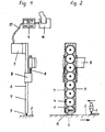
- the measuring device (A) consists of the friction wheel (3), which is pretensioned by the springs (8), the transmission gear (6) with form-fitting wheels (4) arranged one above the other for driving the photoelectric rotary encoder (5).
- the parts (3), (6) and (4) are housed in a common housing (7).
- the dimensions of the measuring device (A) are designed so that the device can also be used when welding deep narrow gaps.
- the measuring device (A) can be adjusted with its housing (7) axially in the adjusting device (B).
- the adjustment device (B) is e.g. connectable to the welding head (not shown).
- the electrical impulses generated in the rotary encoder (5) from a rotational movement are transmitted via a copper cable conductor (II) to a digital tachometer (9) for display and / or can be printed out by a printer (10).
- the measuring and control device (A, B) can be installed in any position.
Landscapes
- Physics & Mathematics (AREA)
- Engineering & Computer Science (AREA)
- Plasma & Fusion (AREA)
- Mechanical Engineering (AREA)
- General Physics & Mathematics (AREA)
- Butt Welding And Welding Of Specific Article (AREA)
- Pressure Welding/Diffusion-Bonding (AREA)
Applications Claiming Priority (2)
| Application Number | Priority Date | Filing Date | Title |
|---|---|---|---|
| DE3618250 | 1986-05-30 | ||
| DE19863618250 DE3618250A1 (de) | 1986-05-30 | 1986-05-30 | Vorrichtung zur messung der schweissvorschubgeschwindigkeit |
Publications (2)
| Publication Number | Publication Date |
|---|---|
| EP0247433A2 true EP0247433A2 (fr) | 1987-12-02 |
| EP0247433A3 EP0247433A3 (fr) | 1989-03-22 |
Family
ID=6301970
Family Applications (1)
| Application Number | Title | Priority Date | Filing Date |
|---|---|---|---|
| EP87106905A Withdrawn EP0247433A3 (fr) | 1986-05-30 | 1987-05-12 | Dispositif de mesure de la vitesse d'avancement de soudage |
Country Status (2)
| Country | Link |
|---|---|
| EP (1) | EP0247433A3 (fr) |
| DE (1) | DE3618250A1 (fr) |
Cited By (1)
| Publication number | Priority date | Publication date | Assignee | Title |
|---|---|---|---|---|
| CN105364347A (zh) * | 2015-11-25 | 2016-03-02 | 深圳市鹏煜威科技有限公司 | 自动筒体生产线 |
Families Citing this family (1)
| Publication number | Priority date | Publication date | Assignee | Title |
|---|---|---|---|---|
| CN103983800B (zh) * | 2014-05-27 | 2016-04-06 | 西南石油大学 | 一种清管器速度采集装置 |
Family Cites Families (8)
| Publication number | Priority date | Publication date | Assignee | Title |
|---|---|---|---|---|
| US3743913A (en) * | 1972-02-24 | 1973-07-03 | Merrick Scale Mfg Co | Mechanism for electrically transmitting the speed of travel of a conveyor belt |
| DE2846500C2 (de) * | 1977-10-31 | 1984-12-06 | Institut problem upravlenija, Moskau/Moskva | Steuerungsverfahren für eine bewegliche Energiequelle beim Erhitzen der Oberfläche eines Objekts und Einrichtung zur Durchführung dieses Verfahrens |
| DE3021659C2 (de) * | 1980-06-10 | 1985-01-17 | M.A.N. Maschinenfabrik Augsburg-Nürnberg AG, 4200 Oberhausen | Verfahren zur Messung und Steuerung der Vorschubgeschwindigkeit von Schweißautomaten |
| JPS595394B2 (ja) * | 1980-07-10 | 1984-02-04 | 住友精密工業株式会社 | 自動隅肉溶接倣い装置 |
| SE451965B (sv) * | 1981-03-17 | 1987-11-09 | Esab Ab | Anordning vid ett svetshuvud for svetsning i tranga fogar |
| DD213612B1 (de) * | 1983-02-22 | 1987-07-22 | Wilfried Faber | Schaltungsanordnung zur ueberwachung von positioniersensoren beim schweissen |
| DE3405909A1 (de) * | 1984-02-18 | 1985-08-22 | Licentia Patent-Verwaltungs-Gmbh, 6000 Frankfurt | Vorrichtung zur erfassung, messtechnischen analyse und/oder regelung von technischen verfahrensablaeufen |
| DE3407590C1 (de) * | 1984-03-01 | 1985-06-13 | Kienzle Apparate Gmbh, 7730 Villingen-Schwenningen | Fotoelektrischer Impulsgeber |
-
1986
- 1986-05-30 DE DE19863618250 patent/DE3618250A1/de not_active Withdrawn
-
1987
- 1987-05-12 EP EP87106905A patent/EP0247433A3/fr not_active Withdrawn
Cited By (1)
| Publication number | Priority date | Publication date | Assignee | Title |
|---|---|---|---|---|
| CN105364347A (zh) * | 2015-11-25 | 2016-03-02 | 深圳市鹏煜威科技有限公司 | 自动筒体生产线 |
Also Published As
| Publication number | Publication date |
|---|---|
| EP0247433A3 (fr) | 1989-03-22 |
| DE3618250A1 (de) | 1987-12-03 |
Similar Documents
| Publication | Publication Date | Title |
|---|---|---|
| DE3021659C2 (de) | Verfahren zur Messung und Steuerung der Vorschubgeschwindigkeit von Schweißautomaten | |
| DE2635766C2 (de) | Verfahren und Vorrichtung zur Funkenerosionsbearbeitung | |
| DE3146046C2 (de) | Steueranordnung für eine Zahnradprüfmaschine | |
| DE2930078C3 (de) | Einrichtung zum selbsttätigen Messen der Eingriffsteilung von Schneckengewinden an Werkstücken | |
| DE2534239C2 (de) | Verfahren und Vorrichtung zur Bildstörung an einer Kreuzspuleinrichtung | |
| EP0247433A2 (fr) | Dispositif de mesure de la vitesse d'avancement de soudage | |
| EP0193864B1 (fr) | Dispositif pour le guidage adaptif d'une tête de sondage | |
| DE3930306C2 (fr) | ||
| DE3117606A1 (de) | "automatisch, beruehrungslose brennerfuehrung auf fugenmitte beim schutzgas-lichtbogenschweissen" | |
| DE1440268B2 (de) | Verfahren und Maschine zum Bearbeiten von Drehflächen durch Elektroerosion | |
| DE2212593C3 (de) | Vorrichtung zum Schneiden eines Glasbandes | |
| DE2712029A1 (de) | Nocken(wellen)schleifmaschine | |
| DE2641851A1 (de) | Brennschneidmaschine | |
| DE3200421A1 (de) | "planetenrollen-vorschub fuer einen abschmelzenden schweissdraht" | |
| DE2042452C3 (de) | Vorrichtung zum Auftragen von Flüssigkeiten auf Folien | |
| DE3878913T2 (de) | Geraet zum selbsttaetigen kehlnahtschweissen eines schweissgegenstandes, bestehend aus einer viereckigen bodenplatte und vier im wesentlichen lotrecht zur erwaehnten bodenplatte zusammengehefteten seitenplatten. | |
| DE2533448C2 (de) | Verfahren und Vorrichtung zur Steuerung maschineller Schweißvorgänge beim Gleichstrom-, Wechselstrom- und Impulslichtbogenschweißen unter Verwendung des Schweißlichtbogens als Sensor | |
| EP0292642A2 (fr) | Procédé et dispositif de commande d'un mécanisme de génération d'une machine à rectifier des roues dentées | |
| DE3531699A1 (de) | Einrichtung an einer folienrohrwickelmaschine zur steuerung einer schneidvorrichtung | |
| DE522200C (de) | Drahtzufuehrungsvorrichtung, insbesondere fuer elektrische Lichtbogenschweissmaschinen | |
| DE2732056C3 (de) | Vorrichtung zur Nachlaufsteuerung an Gelenkarm-Brennschneidmaschine | |
| DE3001596C2 (de) | Kurbelgetriebe | |
| DE760349C (de) | Elektrische Rollennahtschweiss- oder Loetmaschine mit getrenntem Antrieb der einzelnen Rollenelektroden | |
| DE19738519A1 (de) | Verfahren zum Aufwickeln einer Bahn und Vorrichtung zur Durchführung des Verfahrens | |
| DE4026360C2 (fr) |
Legal Events
| Date | Code | Title | Description |
|---|---|---|---|
| PUAI | Public reference made under article 153(3) epc to a published international application that has entered the european phase |
Free format text: ORIGINAL CODE: 0009012 |
|
| AK | Designated contracting states |
Kind code of ref document: A2 Designated state(s): AT CH DE ES FR GB IT LI NL |
|
| PUAL | Search report despatched |
Free format text: ORIGINAL CODE: 0009013 |
|
| RHK1 | Main classification (correction) |
Ipc: B23K 9/12 |
|
| AK | Designated contracting states |
Kind code of ref document: A3 Designated state(s): AT CH DE ES FR GB IT LI NL |
|
| STAA | Information on the status of an ep patent application or granted ep patent |
Free format text: STATUS: THE APPLICATION IS DEEMED TO BE WITHDRAWN |
|
| 18D | Application deemed to be withdrawn |
Effective date: 19890923 |
|
| RIN1 | Information on inventor provided before grant (corrected) |
Inventor name: VEERBECK, BERNHARD Inventor name: ENGEL, ULRICH |