EP0247416A1 - Gleichlauf- und Bremssteuerung - Google Patents
Gleichlauf- und Bremssteuerung Download PDFInfo
- Publication number
- EP0247416A1 EP0247416A1 EP87106748A EP87106748A EP0247416A1 EP 0247416 A1 EP0247416 A1 EP 0247416A1 EP 87106748 A EP87106748 A EP 87106748A EP 87106748 A EP87106748 A EP 87106748A EP 0247416 A1 EP0247416 A1 EP 0247416A1
- Authority
- EP
- European Patent Office
- Prior art keywords
- motors
- motor
- synchronization
- braking control
- speed
- Prior art date
- Legal status (The legal status is an assumption and is not a legal conclusion. Google has not performed a legal analysis and makes no representation as to the accuracy of the status listed.)
- Granted
Links
- 238000004804 winding Methods 0.000 claims abstract description 12
- 230000007257 malfunction Effects 0.000 claims description 2
- 238000000034 method Methods 0.000 description 9
- 230000006378 damage Effects 0.000 description 2
- 230000000694 effects Effects 0.000 description 2
- 241000549194 Euonymus europaeus Species 0.000 description 1
- 238000011161 development Methods 0.000 description 1
- 230000018109 developmental process Effects 0.000 description 1
- 230000010363 phase shift Effects 0.000 description 1
- 230000001960 triggered effect Effects 0.000 description 1
Images
Classifications
-
- H—ELECTRICITY
- H02—GENERATION; CONVERSION OR DISTRIBUTION OF ELECTRIC POWER
- H02P—CONTROL OR REGULATION OF ELECTRIC MOTORS, ELECTRIC GENERATORS OR DYNAMO-ELECTRIC CONVERTERS; CONTROLLING TRANSFORMERS, REACTORS OR CHOKE COILS
- H02P3/00—Arrangements for stopping or slowing electric motors, generators, or dynamo-electric converters
-
- H—ELECTRICITY
- H02—GENERATION; CONVERSION OR DISTRIBUTION OF ELECTRIC POWER
- H02P—CONTROL OR REGULATION OF ELECTRIC MOTORS, ELECTRIC GENERATORS OR DYNAMO-ELECTRIC CONVERTERS; CONTROLLING TRANSFORMERS, REACTORS OR CHOKE COILS
- H02P6/00—Arrangements for controlling synchronous motors or other dynamo-electric motors using electronic commutation dependent on the rotor position; Electronic commutators therefor
- H02P6/24—Arrangements for stopping
-
- G—PHYSICS
- G11—INFORMATION STORAGE
- G11B—INFORMATION STORAGE BASED ON RELATIVE MOVEMENT BETWEEN RECORD CARRIER AND TRANSDUCER
- G11B15/00—Driving, starting or stopping record carriers of filamentary or web form; Driving both such record carriers and heads; Guiding such record carriers or containers therefor; Control thereof; Control of operating function
- G11B15/18—Driving; Starting; Stopping; Arrangements for control or regulation thereof
- G11B15/46—Controlling, regulating, or indicating speed
- G11B15/467—Controlling, regulating, or indicating speed in arrangements for recording or reproducing wherein both record carriers and heads are driven
- G11B15/473—Controlling, regulating, or indicating speed in arrangements for recording or reproducing wherein both record carriers and heads are driven by controlling the speed of the heads
-
- H—ELECTRICITY
- H02—GENERATION; CONVERSION OR DISTRIBUTION OF ELECTRIC POWER
- H02P—CONTROL OR REGULATION OF ELECTRIC MOTORS, ELECTRIC GENERATORS OR DYNAMO-ELECTRIC CONVERTERS; CONTROLLING TRANSFORMERS, REACTORS OR CHOKE COILS
- H02P6/00—Arrangements for controlling synchronous motors or other dynamo-electric motors using electronic commutation dependent on the rotor position; Electronic commutators therefor
- H02P6/04—Arrangements for controlling or regulating the speed or torque of more than one motor
Definitions
- a rotating body e.g. a head drum or a head wheel in a video recorder
- two identical motors e.g. to use electronically commutated DC motors that are mechanically connected to each other via an axial spindle.
- a motor causes the head drum to rotate, which is firmly connected to its motor shaft. This motor is displaceable in the axial direction on a slide or on a linkage. At exactly the same speed of rotation of the second stationary motor, the head drum rotates in one plane without the motors moving relative to one another.
- the individual mutually corresponding windings of the two identical motors for the stopping process after switching off are connected in parallel to one another.
- the individual windings are polarized during the stopping process so that the voltages generated have the same direction at the same speed.
- the individual partial voltages are in phase and an unintentional relative change of the speeds to one another cannot take place.
- phase differences ie, f zs
- voltages are generated which are in phase opposition to one another in sections. This back emf causes an almost abrupt braking effect on both motors, so that the possibility of unintentional relative speed deviations of the motors from one another after the switch-off process is avoided.
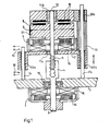
- the head drum 8 forms with motor 6, a unit which is slidably mounted on slide rods 20a, 20b, 20c on a linkage 7a, 7b.
- the electronically commutatable coils 16 are arranged, which are connected in parallel with the corresponding electronically commutated coils 15, of the motor 1 generating the stroke, during the switch-off process.
- the head drum 8 is firmly connected to the shaft 12 and the rotor of motor 6, to which the magnets 17 are attached.
- the shaft 12 is supported in the slide bearings 11a, 11b. It carries a threaded spindle 5 at its free end. This protrudes into a threaded bushing 4 which is firmly connected to the shaft 2 and rotor 14 of motor 1.
- Motor 1 is fixed to the chassis 3, which also carries the linkage 7.
- a magnetic tape 9 is placed on the head drum 8 and is in contact with a magnetic head 21.
- the signals to be recorded or emitted are forwarded by the magnetic head 21 to the windings of a rotary transmitter 10, the fixed part of which is connected to the fixed part of motor 6 via the connecting part 13.
- both motors 1 and 6 have the same rotational speeds in the same direction of rotation, the mechanical distance between the motors is constant. If, on the other hand, motor 1 makes slight, for example sinusoidal, speed changes compared to the speed of motor 6, motor 6 and thus the head drum are displaced in the direction of the arrow via bushing 4 and spindle 5. Thus, on the magnetic tape 9, which is guided in a stationary manner to the chassis 3, magnetic tracks 21 lying adjacent to one another and running parallel to one another are written in accordance with DE-OS 35 42 064. From the figure it can be seen that after a shutdown without electronic control, different rotating masses act on the shafts of the motors 1 and 6, so that a lifting movement is caused by the spindle 4, 5 without special measures, which can lead to the destruction of the arrangement . To avoid this, if the stroke is exceeded by the limit switches 18 and 19, for example, a Shutdown process for both motors are triggered, in which the individual windings of motors 1 and 6 are connected in parallel.
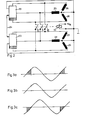
- FIG. 2 shows a circuit of the synchronization and braking control according to the invention.
- the windings 24, 25 and 26 of a first, three-strand motor, whose speed can be controlled by the control unit 22, are shown in star connection, which are mechanically coupled to the windings 27, 28 and 29 by a spindle shown in FIG. 1 with a second motor is.
- the structure and circuit of the second motor corresponds to that of the first motor. Its speed is also controlled electronically by control unit 23. Both control units are connected to one another via a line 34, whereby a desired adjustment of the two speeds to one another can take place during operation.
- FIG. 3a shows, for example, the voltage curve in coil 24 at the switch-off moment and FIG. 3b shows the curve in the parallel coil 27 at the switch-off moment. Both voltages are in phase at the same speed, so that no relative movement can take place between the two motors. If, on the other hand, the speed of one motor is compared to the speed of the other motor, for example due to different flywheels during the stopping process changed, a phase shift is shown, for example, as shown in FIG. 3c compared to 3a and 3b. In this state, the voltages in the shaded area are directed towards each other, which results in electrical braking by the back emf. The further the phases deviate from one another, the stronger the braking effect, ie the braking is almost abrupt, so that undesired relative movements between the two motors are avoided.
- the motor windings are shown in star connection as an example. But even in the case of a delta connection of the windings, it is possible, in the absence of a supply voltage, to carry out parallel connections of corresponding windings with the aid of the relay contacts.
Landscapes
- Engineering & Computer Science (AREA)
- Power Engineering (AREA)
- Stopping Of Electric Motors (AREA)
- Control Of Multiple Motors (AREA)
- Control Of Motors That Do Not Use Commutators (AREA)
- Braking Systems And Boosters (AREA)
- Electric Propulsion And Braking For Vehicles (AREA)
- Braking Arrangements (AREA)
- Regulating Braking Force (AREA)
- Control Of Ac Motors In General (AREA)
Abstract
Description
- Für die Erzeugung von axialen Hubbewegungen eines rotierenden Körpers, z.B. einer Kopftrommel oder eines Kopfrades in einem Videorecorder, ist es aus DE-OS 35 42 064 bekannt, zwei gleichartige Motore, z.B. elektronisch kommutierte Gleichstrommotore zu verwenden, die über eine axiale Spindel miteinander mechanisch verbunden sind. Ein Motor bewirkt die Rotation der Kopftrommel, welche fest mit dessen Motorwelle verbunden ist. Dieser Motor ist in axialer Richtung verschiebbar auf einem Schlitten oder auf einem Gestänge angeordnet. Bei exakt gleicher Drehzahl des zweiten ortsfesten Motors rotiert die Kopftrommel in einer Ebene, ohne daß eine Relativbewegung der Motore zueinander erfolgt. Wird dagegen der zweite Motor geringfügig in seiner Drehzahl relativ zur Kopfraddrehzahl verändert, ergibt sich durch die gemeinsame Spindel eine axiale Relativbewegung zwischen den beiden Motoren. Diese Bewegung, auch Hub genannt, ist abhängig von der Steigung der Spindel und der Drehzahldifferenz der beiden Motore.
- Während des Betriebes wird durch elekronische Steuerung beider Motore sichergestellt, daß eine unbeabsichtigte Hubänderung nicht möglich ist. Beim Abschalten des Gerätes und damit Stromlossetzen der Motore würden sich dagegen unterschiedliche Auslaufdrehzahlen der beiden Motore z.B. durch unterschiedliche rotierende Massen, unterschiedliche Reibungen und Belastungen einstellen, wodurch eine unbeabsichtigte Hubbewegung erfolgt, die unter Umständen zur Zerstörung des Gerätes führen kann.
- Es ist Aufgabe der Erfindung, ein derartiges unbeabsichtigtes Auseinanderlaufen der Auslaufdrehzahlen zweier miteinander zusammenwirkender Motore während eines Abschaltvorganges zu vermeiden und den Auslaufvorgang zu beschleunigen.
- Diese Aufgabe wird gemäß der Erfindung durch eine Gleichlauf-und Bremssteuerung nach dem Oberbegriff des Anspruchs 1 durch die im Kennzeichen des Anspruchs 1 aufgeführten Merkmale gelöst. Weiterbildungen der Erfindung sind in den Unteransprüchen gekennzeichnet.
- Im Prinzip werden die einzelnen einander entsprechenden Wicklungen der beiden gleichartigen Motore für den Auslaufvorgang nach dem Abschalten, zueinander parallel geschaltet. Für die Parallelschaltung werden die einzelnen Wicklungen während des Auslaufvorganges so gepolt, daß bei gleicher Drehzahl die generierten Spannungen gleiche Richtung aufweisen. Solange die Drehzahlen gleich groß sind, sind die einzelnen Teilspannungen in Phase und eine unbeabsichtigte Relativänderung der Drehzahlen zueinander kann nicht erfolgen. Läuft allerdings, durch unterschiedliche rotierende Massen bedingt, die Drehzahl auseinander, ergeben sich Phasendifferenzen, d.h. fzs werden Spannungen erzeugt, die in Teilabschnitten in Gegenphase zueinander sind. Diese Gegen-EMK bewirkt eine nahezu abrupte Bremswirkung auf beide Motore, so daß die Möglichkeit einer unbeabsichtigten relativen Drehzahlabweichungen der Motore zueinander nach dem Abschaltvorgang vermieden wird.
- Die Erfindung wird im folgenden in einem Ausführungsbeispiel anhand der Zeichnungen näher erläutert. Darin zeigen:
- Fig. 1 eine konstruktive Anordnung zweier mittels Gewindespindel mechanisch gekuppelter Motore zur Huberzeugung für eine Kopftrommel
- Fig. 2 eine Schaltung der erfindungsgemäßen Gleichlauf- und Bremssteuerung
- Fig. 3 Spannungsverläufe in den Motorwicklungen.
- Fig. 1 zeigt eine konstruktive Anordnung zweier mittels Gewindespindel mechanisch gekuppelter Motore 1, 6 zur Huberzeugung für eine Kopftrommel 8. Die Kopftrommel 8 bildet mit Motor 6 eine Einheit, die verschiebbar über Gleitlager 20a, 20b, 20c auf einem Gestänge 7a, 7b gelagert ist. Im feststehenden Teil von Motor 6 sind die elektronisch kommutierbaren Spulen 16 angeordnet, die mit den entsprechenden elektronisch kommutierten Spulen 15, des den Hub erzeugenden Motors 1, während des Ausschaltvorganges parallel geschaltet werden. Die Kopftrommel 8 ist mit der Welle 12 und dem Rotor von Motor 6, an welchem die Magnete 17 befestigt sind, fest verbunden. Die Welle 12 ist in den Gleitlagern lla, llb gelagert. Sie trägt an ihrem freien Ende eine Gewindespindel 5. Diese ragt in eine Gewindebuchse 4, die mit der Welle 2 und Rotor 14 von Motor 1 fest verbunden ist. Motor 1 ist mit dem Chassis 3, welches auch das Gestänge 7 trägt, ortsfest verbunden.
- An die Kopftrommel 8 ist ein Magnetband 9 angelegt, welches mit einem Magnetkopf 21 in Berührung steht. Die aufzuzeichnenden bzw. abgegebenen Signale werden vom Magnetkopf 21 an die Wicklungen eines Drehübertragers 10 weitergeleitet, dessen feststehender Teil über das Verbindungsteil 13 mit dem feststehenden Teil von Motor 6 verbunden ist.
- Wenn beide Motore 1 und 6 bei gleicher Drehrichtung gleich große Umdrehungsgeschwindigkeiten aufweisen, ist der mechanische Abstand der Motore voneinander konstant. Führt dagegen Motor 1 geringfügige, z.B. sinusförmig verlaufende Drehzahländerungen gegenüber der Drehzahl von Motor 6 aus, wird Motor 6 und damit die Kopftrommel über Buchse 4 und Spindel 5 in Pfeilrichtung verschoben. Somit werden auf dem Magnetband 9, welches ortsfest zum Chassis 3 geführt ist, vom Magnetkopf 21 nebeneinderliegende, parallel zueinander verlaufende Magnetspuren entsprechend der DE-OS 35 42 064 geschrieben. Aus der Figur ist zu erkennen, daß nach einem Abschaltvorgang ohne elektronische Steuerung unterschiedliche rotierende Massen an den Wellen der Motore 1 und 6 wirken, so daß ohne besondere Maßnahmen durch die Spindel 4, 5 eine Hubbewegung bewirkt wird, die zur Zerstörung der Anordnung führen kann. Um dieses zu vermeiden, kann bei einer Hubüberschreitung durch die Endschalter 18 und 19 z.B. ein Abschaltvorgang für beide Motore ausgelöst werden, bei dem gleichzeitig die einzelnen Wicklungen der Motore 1 und 6 parallel geschaltet werden.
- Fig. 2 zeigt eine Schaltung der erfindungsgemäßen Gleichlauf-und Bremssteuerung. Es sind die Wicklungen 24, 25 und 26 eines ersten, dreisträngigen, durch das Steuergerät 22 in seiner Drehzahl steuerbaren Motors in Sternschaltung dargestellt, der über eine in Fig. 1 gezeigten Spindel mit einem zweiten Motor mit den Wicklungen 27, 28 und 29 mechanisch gekoppelt ist. Der zweite Motor entspricht in seinem Aufbau und seiner Schaltung dem ersten Motor. Er wird ebenfalls elektronisch durch Steuergerät 23 in seiner Drehzahl gesteuert. Beide Steuergeräte sind über eine Leitung 34 miteinander verbunden, wodurch im Betrieb ein gewünschter Abgleich der beiden Drehzahlen zueinander erfolgen kann.
- Im Abschalt- oder Störungsfall z.B. durch Ausfall des Netzes ist eine Nachsteuerung nicht mehr gegeben, so daß die Motore unterschiedliche Drehzahlen annehmen würden. Dieser Zustand wird verhindert durch die Schalter 30, 31 und 32 von Relais 33, die im Betriebszustand geöffnet sind und bei Fehlen einer Spannung +UB am Relais 33 geschlossen werden. Durch das Schließen der Schalter 30, 31 und 32 wird Spule 24 vom ersten Motor mit Spule 27 vom zweiten Motor, Spule 25 vom ersten Motor mit Spule 28 vom zweiten Motor und Spule 26 vom ersten Motor mit Spule 29 vom zweiten Motor parallel geschaltet. Durch die Parallelschaltung werden während des Auslaufvorganges Spannungen erzeugt, wie sie Fig. 3 zeigt.
- Fig. 3a zeigt z.B. den Spannungsverlauf in Spule 24 im Abschaltmoment und Fig. 3b den Verlauf in der parallelgeschalteten Spule 27 im Abschaltmoment. Beide Spannungen sind bei gleicher Drehzahl in Phase, so daß keine Relativbewegung zwischen den beiden Motoren stattfinden kann. Wird dagegen die Drehzahl eines Motors z.B. durch unterschiedliche Schwungmassen während des Auslaufvorganges gegenüber der Drehzahl des anderen Motors verändert, zeigt sich z.B. eine Phasenverschiebung, wie sie in Fig. 3c gegenüber 3a und 3b dargestellt ist. In diesem Zustand sind die Spannungen im schraffierten Bereich gegeneinander gerichtet, wodurch eine elektrische Bremsung durch die Gegen-EMK erfolgt. Je weiter die Phasen voneinander abweichen, um so stärker ist die Bremswirkung, d.h. die'Bremsung ist nahezu abrupt, so daß unerwünschte Relativbewegungen zwischen den beiden Motoren vermieden werden.
- Beispielhaft sind die Motorwicklungen in Sternschaltung dargestellt. Aber auch bei Dreieckschaltung der Wicklungen ist es möglich, bei Fehlen einer Versorgungsspannung eine Parallelschaltung einander entsprechender Wicklungen mit Hilfe der Relaiskontakte durchzuführen.
Claims (4)
Priority Applications (1)
| Application Number | Priority Date | Filing Date | Title |
|---|---|---|---|
| AT87106748T ATE55662T1 (de) | 1986-05-17 | 1987-05-08 | Gleichlauf- und bremssteuerung. |
Applications Claiming Priority (2)
| Application Number | Priority Date | Filing Date | Title |
|---|---|---|---|
| DE19863616845 DE3616845A1 (de) | 1986-05-17 | 1986-05-17 | Gleichlauf- und bremssteuerung |
| DE3616845 | 1986-05-17 |
Publications (2)
| Publication Number | Publication Date |
|---|---|
| EP0247416A1 true EP0247416A1 (de) | 1987-12-02 |
| EP0247416B1 EP0247416B1 (de) | 1990-08-16 |
Family
ID=6301173
Family Applications (1)
| Application Number | Title | Priority Date | Filing Date |
|---|---|---|---|
| EP87106748A Expired - Lifetime EP0247416B1 (de) | 1986-05-17 | 1987-05-08 | Gleichlauf- und Bremssteuerung |
Country Status (7)
| Country | Link |
|---|---|
| EP (1) | EP0247416B1 (de) |
| JP (1) | JPS62277097A (de) |
| KR (1) | KR910001784B1 (de) |
| AT (1) | ATE55662T1 (de) |
| DE (2) | DE3616845A1 (de) |
| ES (1) | ES2016946B3 (de) |
| GR (1) | GR3001076T3 (de) |
Citations (5)
| Publication number | Priority date | Publication date | Assignee | Title |
|---|---|---|---|---|
| CH527513A (de) * | 1971-02-13 | 1972-08-31 | Siemens Ag | Spinnturbine mit einem drehzahlgeregelten, abbremsbaren elektrischen Antriebsmotor |
| US4347536A (en) * | 1979-01-10 | 1982-08-31 | Hitachi, Ltd. | Rotary cylinder apparatus |
| EP0097916A2 (de) * | 1982-06-25 | 1984-01-11 | Hitachi, Ltd. | Energieversorgung für Mehrmotorenantriebe |
| DE3307324A1 (de) * | 1983-03-02 | 1984-09-06 | Telefunken Fernseh Und Rundfunk Gmbh, 3000 Hannover | Videorecorder mit schraegspuraufzeichnung |
| EP0224211A2 (de) * | 1985-11-28 | 1987-06-03 | Deutsche Thomson-Brandt GmbH | Kopfradanordnung für einen Recorder |
-
1986
- 1986-05-17 DE DE19863616845 patent/DE3616845A1/de not_active Withdrawn
-
1987
- 1987-05-08 AT AT87106748T patent/ATE55662T1/de not_active IP Right Cessation
- 1987-05-08 DE DE8787106748T patent/DE3764312D1/de not_active Expired - Fee Related
- 1987-05-08 ES ES87106748T patent/ES2016946B3/es not_active Expired - Lifetime
- 1987-05-08 EP EP87106748A patent/EP0247416B1/de not_active Expired - Lifetime
- 1987-05-16 KR KR1019870004839A patent/KR910001784B1/ko not_active Expired
- 1987-05-18 JP JP62119141A patent/JPS62277097A/ja active Granted
-
1990
- 1990-11-15 GR GR90400919T patent/GR3001076T3/el unknown
Patent Citations (5)
| Publication number | Priority date | Publication date | Assignee | Title |
|---|---|---|---|---|
| CH527513A (de) * | 1971-02-13 | 1972-08-31 | Siemens Ag | Spinnturbine mit einem drehzahlgeregelten, abbremsbaren elektrischen Antriebsmotor |
| US4347536A (en) * | 1979-01-10 | 1982-08-31 | Hitachi, Ltd. | Rotary cylinder apparatus |
| EP0097916A2 (de) * | 1982-06-25 | 1984-01-11 | Hitachi, Ltd. | Energieversorgung für Mehrmotorenantriebe |
| DE3307324A1 (de) * | 1983-03-02 | 1984-09-06 | Telefunken Fernseh Und Rundfunk Gmbh, 3000 Hannover | Videorecorder mit schraegspuraufzeichnung |
| EP0224211A2 (de) * | 1985-11-28 | 1987-06-03 | Deutsche Thomson-Brandt GmbH | Kopfradanordnung für einen Recorder |
Also Published As
| Publication number | Publication date |
|---|---|
| ES2016946B3 (es) | 1990-12-16 |
| JPH0568200B2 (de) | 1993-09-28 |
| KR910001784B1 (ko) | 1991-03-23 |
| DE3764312D1 (de) | 1990-09-20 |
| KR870011744A (ko) | 1987-12-26 |
| JPS62277097A (ja) | 1987-12-01 |
| ATE55662T1 (de) | 1990-09-15 |
| GR3001076T3 (en) | 1992-04-17 |
| EP0247416B1 (de) | 1990-08-16 |
| DE3616845A1 (de) | 1987-11-19 |
Similar Documents
| Publication | Publication Date | Title |
|---|---|---|
| DE69011001T2 (de) | Presse mit Steuerschaltungsanordnung. | |
| DE3535895A1 (de) | Elektrische betaetigungsvorrichtung, insbesonder fuer ventile | |
| DE2556952A1 (de) | Kombiniertes, digitales steuerungs- und regelungssystem fuer einen gleichstrommotor | |
| DE3819062C2 (de) | ||
| EP3491655A1 (de) | Motorvorrichtung für einen schalterantrieb eines elektrischen schalters | |
| DE3740551C2 (de) | Datenspeichergerät mit einem rotierenden Datenträger | |
| EP1699676B1 (de) | Verfahren zum abbremsen eines elektromotors und elektrischer antrieb | |
| DE3128627A1 (de) | Servoeinrichtung zur reglung der geschwindigkeit und phase einer rotierenden vorrichtung | |
| EP0247416B1 (de) | Gleichlauf- und Bremssteuerung | |
| DE102004032680B4 (de) | Motorbremse für ein elektrisch angetriebenes Fahrzeug | |
| DE4442151A1 (de) | Schaltungsanordnung zum Steuern eines elektronisch kommutierten Motors | |
| DE102004019284A1 (de) | Vorrichtung zum Betrieb eines Synchronmotors | |
| EP0334160A2 (de) | Einrichtung zur Einstellung des Lastwinkels eines elektrischen Schrittmotors | |
| EP0196539B1 (de) | Digitale Drehzahlregelschaltung für einen Gleichstrommotor | |
| DE3542064A1 (de) | Kopfradanordnung fuer einen recorder | |
| EP1070383B1 (de) | Verfahren und vorrichtung zur ansteuerung eines elektronisch kommutierten mehrphasen-gleichstrommotors | |
| EP2475497A1 (de) | Rundschalttisch | |
| EP1275197B1 (de) | Anordnungen zum lagegeregelten stillsetzen rotierender bauteile mit lagegeregelten antrieben bei spannungsausfall | |
| DE2044736C2 (de) | Anordnung zur Regelung der Geschwindigkeit zwischen zwei relativ zueinander bewegbaren Teilen | |
| DE4316292A1 (de) | Elektrischer Stellantrieb | |
| EP0372095B1 (de) | Elektromotorischer Antrieb | |
| DE69123419T2 (de) | Aufzeichnungsgerät und Wiedergabegerät mit drehbaren Magnetköpfen | |
| DE4125892C2 (de) | Steuerungsanordnung für einen winkelschrittgesteuerten Elektromotor | |
| DE19853452C1 (de) | Robotervorrichtung | |
| DD282552A5 (de) | Schaltungsanordnung zum bremsen von drehstrommotoren |
Legal Events
| Date | Code | Title | Description |
|---|---|---|---|
| PUAI | Public reference made under article 153(3) epc to a published international application that has entered the european phase |
Free format text: ORIGINAL CODE: 0009012 |
|
| AK | Designated contracting states |
Kind code of ref document: A1 Designated state(s): AT BE CH DE ES FR GB GR IT LI LU NL SE |
|
| 17P | Request for examination filed |
Effective date: 19880105 |
|
| 17Q | First examination report despatched |
Effective date: 19900125 |
|
| GRAA | (expected) grant |
Free format text: ORIGINAL CODE: 0009210 |
|
| ITF | It: translation for a ep patent filed | ||
| AK | Designated contracting states |
Kind code of ref document: B1 Designated state(s): AT BE CH DE ES FR GB GR IT LI LU NL SE |
|
| REF | Corresponds to: |
Ref document number: 55662 Country of ref document: AT Date of ref document: 19900915 Kind code of ref document: T |
|
| REF | Corresponds to: |
Ref document number: 3764312 Country of ref document: DE Date of ref document: 19900920 |
|
| GBT | Gb: translation of ep patent filed (gb section 77(6)(a)/1977) | ||
| ET | Fr: translation filed | ||
| ITTA | It: last paid annual fee | ||
| PLBE | No opposition filed within time limit |
Free format text: ORIGINAL CODE: 0009261 |
|
| STAA | Information on the status of an ep patent application or granted ep patent |
Free format text: STATUS: NO OPPOSITION FILED WITHIN TIME LIMIT |
|
| REG | Reference to a national code |
Ref country code: GR Ref legal event code: FG4A Free format text: 3001076 |
|
| 26N | No opposition filed | ||
| PGFP | Annual fee paid to national office [announced via postgrant information from national office to epo] |
Ref country code: LU Payment date: 19920423 Year of fee payment: 6 |
|
| PGFP | Annual fee paid to national office [announced via postgrant information from national office to epo] |
Ref country code: GB Payment date: 19920429 Year of fee payment: 6 |
|
| PGFP | Annual fee paid to national office [announced via postgrant information from national office to epo] |
Ref country code: ES Payment date: 19920511 Year of fee payment: 6 |
|
| PGFP | Annual fee paid to national office [announced via postgrant information from national office to epo] |
Ref country code: AT Payment date: 19920512 Year of fee payment: 6 |
|
| PGFP | Annual fee paid to national office [announced via postgrant information from national office to epo] |
Ref country code: SE Payment date: 19920515 Year of fee payment: 6 |
|
| PGFP | Annual fee paid to national office [announced via postgrant information from national office to epo] |
Ref country code: BE Payment date: 19920520 Year of fee payment: 6 |
|
| PGFP | Annual fee paid to national office [announced via postgrant information from national office to epo] |
Ref country code: GR Payment date: 19920521 Year of fee payment: 6 |
|
| PGFP | Annual fee paid to national office [announced via postgrant information from national office to epo] |
Ref country code: FR Payment date: 19920526 Year of fee payment: 6 |
|
| PGFP | Annual fee paid to national office [announced via postgrant information from national office to epo] |
Ref country code: CH Payment date: 19920529 Year of fee payment: 6 |
|
| PGFP | Annual fee paid to national office [announced via postgrant information from national office to epo] |
Ref country code: NL Payment date: 19920531 Year of fee payment: 6 |
|
| PGFP | Annual fee paid to national office [announced via postgrant information from national office to epo] |
Ref country code: DE Payment date: 19920731 Year of fee payment: 6 |
|
| EPTA | Lu: last paid annual fee | ||
| PG25 | Lapsed in a contracting state [announced via postgrant information from national office to epo] |
Ref country code: LU Free format text: LAPSE BECAUSE OF NON-PAYMENT OF DUE FEES Effective date: 19930508 Ref country code: GB Effective date: 19930508 Ref country code: AT Effective date: 19930508 |
|
| PG25 | Lapsed in a contracting state [announced via postgrant information from national office to epo] |
Ref country code: SE Effective date: 19930509 |
|
| PG25 | Lapsed in a contracting state [announced via postgrant information from national office to epo] |
Ref country code: ES Free format text: LAPSE BECAUSE OF NON-PAYMENT OF DUE FEES Effective date: 19930510 |
|
| PG25 | Lapsed in a contracting state [announced via postgrant information from national office to epo] |
Ref country code: LI Effective date: 19930531 Ref country code: CH Effective date: 19930531 Ref country code: BE Effective date: 19930531 |
|
| BERE | Be: lapsed |
Owner name: DEUTSCHE THOMSON-BRANDT G.M.B.H. Effective date: 19930531 |
|
| PG25 | Lapsed in a contracting state [announced via postgrant information from national office to epo] |
Ref country code: GR Free format text: THE PATENT HAS BEEN ANNULLED BY A DECISION OF A NATIONAL AUTHORITY Effective date: 19931130 |
|
| PG25 | Lapsed in a contracting state [announced via postgrant information from national office to epo] |
Ref country code: NL Effective date: 19931201 |
|
| GBPC | Gb: european patent ceased through non-payment of renewal fee |
Effective date: 19930508 |
|
| NLV4 | Nl: lapsed or anulled due to non-payment of the annual fee | ||
| PG25 | Lapsed in a contracting state [announced via postgrant information from national office to epo] |
Ref country code: FR Effective date: 19940131 |
|
| REG | Reference to a national code |
Ref country code: CH Ref legal event code: PL |
|
| PG25 | Lapsed in a contracting state [announced via postgrant information from national office to epo] |
Ref country code: DE Effective date: 19940201 |
|
| REG | Reference to a national code |
Ref country code: FR Ref legal event code: ST |
|
| REG | Reference to a national code |
Ref country code: GR Ref legal event code: MM2A Free format text: 3001076 |
|
| EUG | Se: european patent has lapsed |
Ref document number: 87106748.4 Effective date: 19931210 |
|
| REG | Reference to a national code |
Ref country code: ES Ref legal event code: FD2A Effective date: 19990201 |
|
| PG25 | Lapsed in a contracting state [announced via postgrant information from national office to epo] |
Ref country code: IT Free format text: LAPSE BECAUSE OF NON-PAYMENT OF DUE FEES;WARNING: LAPSES OF ITALIAN PATENTS WITH EFFECTIVE DATE BEFORE 2007 MAY HAVE OCCURRED AT ANY TIME BEFORE 2007. THE CORRECT EFFECTIVE DATE MAY BE DIFFERENT FROM THE ONE RECORDED. Effective date: 20050508 |