EP0097916A2 - Energieversorgung für Mehrmotorenantriebe - Google Patents
Energieversorgung für Mehrmotorenantriebe Download PDFInfo
- Publication number
- EP0097916A2 EP0097916A2 EP83106107A EP83106107A EP0097916A2 EP 0097916 A2 EP0097916 A2 EP 0097916A2 EP 83106107 A EP83106107 A EP 83106107A EP 83106107 A EP83106107 A EP 83106107A EP 0097916 A2 EP0097916 A2 EP 0097916A2
- Authority
- EP
- European Patent Office
- Prior art keywords
- voltage
- motor driving
- motor
- power supply
- motors
- Prior art date
- Legal status (The legal status is an assumption and is not a legal conclusion. Google has not performed a legal analysis and makes no representation as to the accuracy of the status listed.)
- Withdrawn
Links
- 239000003990 capacitor Substances 0.000 claims description 23
- 238000001914 filtration Methods 0.000 claims 1
- 238000010586 diagram Methods 0.000 description 17
- 238000001514 detection method Methods 0.000 description 1
- 238000009499 grossing Methods 0.000 description 1
- 229920006395 saturated elastomer Polymers 0.000 description 1
Images

Classifications
-
- H—ELECTRICITY
- H02—GENERATION; CONVERSION OR DISTRIBUTION OF ELECTRIC POWER
- H02P—CONTROL OR REGULATION OF ELECTRIC MOTORS, ELECTRIC GENERATORS OR DYNAMO-ELECTRIC CONVERTERS; CONTROLLING TRANSFORMERS, REACTORS OR CHOKE COILS
- H02P5/00—Arrangements specially adapted for regulating or controlling the speed or torque of two or more electric motors
- H02P5/68—Arrangements specially adapted for regulating or controlling the speed or torque of two or more electric motors controlling two or more DC dynamo-electric motors
-
- H—ELECTRICITY
- H02—GENERATION; CONVERSION OR DISTRIBUTION OF ELECTRIC POWER
- H02P—CONTROL OR REGULATION OF ELECTRIC MOTORS, ELECTRIC GENERATORS OR DYNAMO-ELECTRIC CONVERTERS; CONTROLLING TRANSFORMERS, REACTORS OR CHOKE COILS
- H02P5/00—Arrangements specially adapted for regulating or controlling the speed or torque of two or more electric motors
- H02P5/60—Arrangements specially adapted for regulating or controlling the speed or torque of two or more electric motors controlling combinations of DC and AC dynamo-electric motors
-
- H—ELECTRICITY
- H02—GENERATION; CONVERSION OR DISTRIBUTION OF ELECTRIC POWER
- H02P—CONTROL OR REGULATION OF ELECTRIC MOTORS, ELECTRIC GENERATORS OR DYNAMO-ELECTRIC CONVERTERS; CONTROLLING TRANSFORMERS, REACTORS OR CHOKE COILS
- H02P6/00—Arrangements for controlling synchronous motors or other dynamo-electric motors using electronic commutation dependent on the rotor position; Electronic commutators therefor
- H02P6/04—Arrangements for controlling or regulating the speed or torque of more than one motor
Definitions
- the present invention relates to an electric power supply system for a plurality of motors and drivers therefor.
- a voltage in the form of pulses obtained from an output of a voltage supply source 1 by successively turning a switch 2 on and off is smoothed by a smoothing circuit composed of a diode 3, a choke coil 4 and a capacitor 5 to provide a power source for a brushless motor 24 and a motor driving circuit 27.
- the motor driving circuit 27 is controlled by an input control signal applied to a terminal 15 so that a desired motor torque can be obtained by suitably changing the input control signal.
- the voltage to be applied to the motor to ontain the desired torque varies depending on the load for the motor 24 and the speed of revolution of the motor.
- the voltage applied to the motor driving circuit 27 is detected by a voltage detecting circuit 26 and the detected signal is negatively fed back to a variable voltage power supply circuit 25.
- a high efficiency switching regulator circuit or the like in the variable voltage power supply circuit 25 a minimum voltage which is sufficiently small but can just satisfy the request by the motor 24 and the motor . driving circuit 27, is supplied to the motor 24 and the motor driving circuit 27 to thereby reduce the power losses consumed thereat.
- the variable voltage power supply circuit 25 may be a well-known DC-DC converter which may be constituted by a sawtooth generating curcuit 6, a comparator 7 having an input supplied with the output of the sawtooth generating circuit 6, and an error amplifier 9 for comparing the output of the voltage detecting circuit-26 with a reference voltage source 8 and for amplifying the difference therebetween.
- the motor driving circuit 27 is constituted by a position detector 17 for detecting the rotational potion of a rotor magnet (not-shown) attached to a motor shaft, and a commutator circuit 16 for controlling the conduction period of transistors 18 to 20 which are successively turned on to pass a current into motor driving coils 21 to 23. -The amount of current which flows in the conduction period of the transistors 18 to 20 is controlled in response to the control signal applied to the terminal 15 so that the motor driving coils 21 to 23 are driven by a predetermined constant current commanded by this control signal.
- the lowest one of the collector potentials of the transistors 18 to 20 is detected by diodes 12 to 14 which are biased by a resistor 11 and a reference voltage source 10 and negatively fed back to the variable voltage power supply circuit 25 through the voltage detecting circuit 26.
- the output of the variable voltage power supply circuit 25 is controlled such that the potential at the common junction of the diodes 12 to 14 is made to be equal to the output voltage of the reference voltage source 8. It is a matter of cource that in order to cause the transistors 18 to 21 to pass a current by the amount commanded by the above-mentioned control signal, the voltage applied across the collector-emitter circuit of the'transistors should be within the operative or active region of each transistor.
- the output of the reference voltage source 8 is set to the lowest limit voltage (Vr) of the operative voltage region in which all the transistors 18, to 20 can be operable, it is possible to make minimum the total power losses consumed in these transistors, while allowing each transistor to draw a predetermined current thereinto.
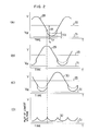
- Diagrams (A) to (D) of Fig. 2 illustrate the collector waveforms of the transistors 18 to 20 when the motor is rotated at a predetermined speed in the circuit attangement as shown in Fig. 1.
- Reference numeral 33 designates the output voltage of the variable voltage power source circuit 25 and assume now, for the sake of explanation, that the power supply circuit 25 is a constant voltage supply source so that its output voltage is fixed to a constant value as indicated by the reference 33.
- the abscissa represents time and the ordinate the collector-emitter voltage V ce and reference numerals 28 to 30 in the diagrams (A) to (C) designate the collector voltage waveforms of the transistors 18 to 20 respectively.
- each collector voltage waveform is approximate to a sinusoidal wave of a frequency proportional to the rotational speed of the motor.
- each of the waveforms 28 to 30 includes a waveform of voltage drop 6V d due to the resistive component included in the respective motor driving coils 21 to 23, during the conductive period of the respective coils 21 to 23.
- Reference numeral 32 in the diagram (D) in Fig. 4 designates a waveform which has been obtained by plotting, on one and the same time axis, the lowest one of the collector voltage levels every instant on the respective time axes of the collector voltage waveforms of the transistors 18 to 20.
- Reference numeral 31 designates the output voltage Vrof the reference voltage source 8.
- the power supply circuit 25 produces an output voltage such that that collector voltage which is the lowest level among the other two corrector voltages at the above-mentioned every instant becomes equal to the output voltage of the reference voltage source 8 so that a necessary minimum voltage is applied to the transistor. If the time t l is now considered, for example, in Fig. 2(A), the output voltage of the power supply circuit 25 is the sum of the output voltage Vrof the reference voltage source 8 and the voltage Vcapplied across the motor driving coil 21.
- the output voltage of the power supply circuit 25 includes a voltage ripple whoes component of the frequency is integer times as large as the frequency of the counter electromotive force induced in the respective coils 21 to 23 as shown in the voltage waveform 32 in Fig. 2(D).
- a low-pass filter or the like is provided between the common junction of the diodes 12 to 14 and the input terminal of the error amplifier 9, and in such a case, an output waveform which does not respond to the frequency of the waveform of the counter electromotive force induced in the respective coils 21 to 23 can be obtained from the variable voltage power supply circuit 25.
- variable voltage power supply circuits are employed when a plurality of motors are to be driven.
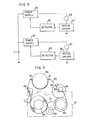
- An arrangement for such a case is shown in a block diagram in Fig. 3.
- the same reference numeral designates the same function as that in Fig. 1.
- a motor 37 and a driving circuit 36 for driving the motor 37 is newly required and therefore a variable voltage power supply circuit 34 and a voltage detecting circuit 35 are additionally provided.
- An object of the present invention is to provide a power supply system in which a single power supply circuit is used for efficiently driving a plurality of motors.
- Another object of the present invention is to provide a power supply system for driving a plurality of motors with a simple arrangement.
- a further object of the present invention is to provide an inexpensive power supply system for driving a plurality of motors.
- the power supply system for driving a plurality of motors is constituted such that when the motors are simultaneously or successively driven at a predetermined rotational speed or a predetermined torque, a single variable voltage power supply circuit is used for supplying the respective motors with power and each of the motors is driven with a constant current by a current control circuit connected to the driving coils of the motor, and such that when the motors are to be rotated at the predetermined rotational speed or torque, the voltage applied to the current control circuit connected to the motor which is supplied with the highest one of the voltages applied to the respective motors is fed back to the power supply circuit to control the output voltage of the power supply circuit such that one of the motors which requires the highest one of the voltages to be applied to the respective motors is supplied with the required voltage and that the minimum voltage necessary for all the constant current driving control circuits to perform their constant current driving operation, that is the lowest limit voltage of the range of the operative voltage of all the current control circuits, is applied to the respective current control circuits.
- FIG. 4 is a block diagram illustrating an example of the present invention
- Fig. 5 is a schematic diagram illustrating the arrangement of a magnetic recording/ reproducing apparatus to which the present invention is suitably applied
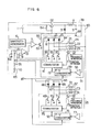
- Fig. 6 is a particular circuit diagram illustrating a preferable embodiment of the present invention.
- a pair of a motor 37 and a motor driving circuit or unit 93 connected to the motor 37 are connected in parallel with another pair of a motor 24 and a motor driving circuit or unit 91, and both the pairs are connected to one and the same power supply circuit 38.
- Voltage detecting circuit 64 and 65 are connected to the motor driving circuits 91 and 93 respectively and both the outputs of the respective voltage detecting circuits 64 and 65 are connected to a control signal generating circuit 63.
- the output of the control signal generating circuit 63 is connected to the power supply circuit 38.
- the motors 24 and 37 are subjected to the rotational speed control or output torque control by the motor driving circuits 91 and 93 respectively and each driven with a constant current.
- the voltages appearing at the motor driving circuits 91, 93 are related to the voltages applied across the motors 24, 37, i.e., they are the difference voltages between the output voltage of the power supply circuit 38 and the voltages applied to the motors 24, 37, respectively.
- the output of one of the voltage detecting circuits 64 and 65 for detecting the voltages applied to the respective motor driving circuits 91 and 93 is selected or detected by the control signal generating circuit 63 as the output of the voltage detecting circuit (64 or 65) for the motor (24 or 37) which requires a voltage higher than that required for the other motor (37 or 24).
- the output of the voltage detecting circuit connected to one of the motor driving circuits (91 or 93) which is supplied with a voltage lower than the other (93 or 91) is selected or detected.
- the thus selected or detected output of the motor driving circuit is supplied to the variable voltage supply circuit 38 as a feedback or control signal thereto.
- the output of the variable voltage supply circuit 38 varies in accordance with the voltage request by one of the two pairs of motor and motor driving circuit which require a voltage higher than the other.
- the other motor driving circuit which is operable by a voltage lower than that is actually applied shoulders the excessive amount of voltage which would be otherwise supplied to the motor because the motor is driven with a constant current, with the result that the motor is not affected by the deviations in power supply voltage.
- reference numeral 39 designates a rotary cylinder provided with a picture recording/reproducing head; 40 and 41, loading pins; 42, a tension pin; 43, a magnetic tape; 44, a capstan; 45, a capstan motor; 46, a pinch roller; 47, a cassette casing or halves in which the magnetic tape 43 is loaded; 48, a supply reel; 49, a take-up reel; 50, a reel motor; and 51, an idler which may be pressed against the shaft of the reel motor to be thereby rotated to transmit the motor power to the selected one of the supply and take-up reels depending on the direction of revolution by engaging with the selected reel.
- the tape 43 is pressed against the capstan 44 of the pinch roller 46 so that it is rotated to run on the cylinder 39.
- the reel motor 50 is driven and the idler 51 is pressed to the take-up reel 49 to be rotated to thereby take-up the tape.
- variable speed reproducing is generally performed to achieve a plurality of modes, such as a slow operation, a search operation, etc., by changing over the capstan speed.
- the respective speeds of the capstan motor 45 and the reel motor 50 are proportionally changed.
- the supply voltages required for the respective motors vary proportionally. It will be easily understood that relatively approximate values of the supply voltages required by the two motors in each of the variable speed reproducing modes can be obtained by suitably designing the motors, for example by suitably designing the strength of the magnetic field of the rotor magnet, the number of turns of the driving coils, etc.
- the power supply system according to the present invention is suitable to the driving circuits for the thus designed, two motors.
- reference numeral 38 designates a variable power supply circuit in which the emitter, collector and base of an NPN transistor 52 are connected to the positive output of a power supply source 1, the connection point between one end of a choke coil 4 as well as the cathode of a diode 3, and the collector of an NPN transistor 53 through a resistor 55, respectively.
- a resistor 54 is inserted between the emitter and base of the transistor 52.
- the base and emitter of the transistor 53 are connected to the output of a comparator 7 and the ground, that is, a negative output line 88 of the variable voltage supply circuit 38, respectively.
- the other end of the choke coil 4 is connected to a positive output line 60 of the variable voltage supply circuit 38.
- One end of a capacitor 5 is connected to the other end of the choke coil 4.
- the anode of the diode 3 and the other end of the capacitor 5 are commonly connected to the positive output line 88 of the variable voltage power supply circuit 38.
- One and the other inputs of the comparator 7 are connected to the output of a sawtooth generator 6 and the output of an error amplifier 9 respectively.
- One of two inputs of the error amplifier 9 is connected to the positive output of a reference voltage source 8.
- a motor 24 has three driving coils 21 to 23 which are commonly connected at their one ends to the positive output line 60 of the variable voltage supply circuit 38.
- the other ends of the driving coils 21 to 23 are respectively connected to the collectors of transistors 18 to 20 in a motor driving circuit 91.
- the respective emitters of the transistors 18 to 20 are commonly connected to the negative output line 88 and the respective bases of the same transistors are connected to a commutator circuit 16.
- a position detector 17 and a frequency generator 57 both provided on the motor are connected to the commutator circuit 16 and the input of an amplifier 58 respectively.
- the output of the amplifier 58 is connected to a terminal 15 of the commutator circuit 16 through a frequency-voltage converter 59.
- Diodes 12 to 14 constitute a voltage detecting circuit 64.
- the cathodes of the diodes 12 to 14 are connected to the collectors of the transistors 18 to 20 respectively, while the anodes of the same diodes are commonly connected to each other.
- the circuit arrangement associated with a motor 37 is quite the same as the above-mentioned arrangement with respect to the motor 24. That is, the motor 37 has three driving coils 72 to 74 and the respective one ends of the coils 72 to 74 are commonly connected to the positive output line 60 of the variable voltage supply circuit 38. The other ends of the driving coils 72 to 74 are respectively connected to the collectors of transistors 69 to 71 of a motor driving circuit 36. The respective emitters of the transistors 69 to 71 are commonly connected to the negative output line 88 and the respective bases of the same transistors are connected to a commutator circuit 75. A position detector 79 and a frequency generator 78 both provided on the motor 37 are connected to the commutator circuit 75 and the input of an amplifier 77 respectively.
- the output of the amplifier 77 is connected to a terminal 92 of the commutator circuit 75 through a frequency-voltage converter 76.
- Diodes 66 to 68 constitute another voltage detecting circuit 65.
- the cathodes of the diodes 66 to 68 are connected to the collectors of the transistors 69 to 71 respectively, while the anodes of the same diodes are commonly connected to each other.
- the common connection point of the anodes of the diodes 12 to 14 constituting the voltage detecting circuit 64 is connected to the junction between the respective one ends of resistors 56 and 61 which constitute a control signal generating circuit 63 together with a voltage source 10 and a capacitor 62.
- the common connection point of the anodes of the diodes 66 to 68 constituting the other voltage detecting circuit 65 is connected to the same junction between the resistors 56 and 61 of the control signal generating circuit 63.
- the other end of the resistor 56 is connected to the positive output of the voltage source 10 and the other end of the resistor 61 is connected to one end of the capacitor 62.
- the other end of the capacitor 62 is connected to the ground, that is, the negative output of the voltage source 10.
- the junction point between the resistor 61 and the capacitor 62 is connected to the other input terminal of the error amplifier 9.
- An input terminal 87 is connected to a mode change-over input of each of the frequency-voltage converter 59 and 76.
- the motors 24 and 37 respectively correspond to the capstan motor 45 and the reel motor 50 of Fig. 5.
- the transistor 52 in the variable voltage supply circuit 38 corresponds to the switch 2 in Fig. 1 and intermittently supplies the voltage of the supply source 1 to the choke coil 4 in response to the output pulse of the comparator 7.
- the resistor 54 is for providing the base current bias for the transistor 52 so as to improve the switching characteristic of the transistor 52.
- the resistor 55 limits the base current of the transistor 52.
- the transistor 53 receives the output of the comparator 7 and drives the transistor 52.
- the output voltage of the variable voltage supply circuit 38 is determined such that the difference between the output voltage of the reference voltage source 8 connected to the one input of the comparator 7 and the applied voltage to the other input of the same comparator 7 is made to be zero. Since the explanation made above with respect to Fig. 1 applies to the operation of the variable voltage supply circuit 38 and since the operation of such a DC-DC converter is generally well known, further description with respect to the operation is omitted here.
- a velocity control loop is provided to which a signal indicating the rotational speed of the motor is inputted as a control signal for the motor.
- the frequency generator 57 produces a signal of a frequency corresponding to the rotational speed of the motor 24.
- the thus produced signal is applied to the amplifier 58 and amplified thereat.
- the amplified signal is then applied to the frequency-voltage converter 59 which converts the amplified signal into a DC voltage corresponding to the frequency of the signal. This DC voltage may be shifted by a predetermined value by changing over the motor speed changing-over signal applied to the frequency-voltage converter 59.
- the signal inputted to an input terminal 87 is changed over to change-over the motor speed to thereby set a variable speed reproducing mode, such as a slow mode, a search mode, etc.
- a variable speed reproducing mode such as a slow mode, a search mode, etc.
- the current flowing in the respective driving coils 21 to 23 of the motor 24 is controlled so that the motor 24 rotates at a predetermined rotational speed.
- the frequency-voltage converter 59 may be, for example, such a type as disclosed in U.S. Patent No. 4,338,554, assigned to Hitachi Ltd., and issued June 6,1982 to Isao Fukushima et al. (corresponding to Japanese Patent Laid-open No. 144788/80 laid open on November 11,- 1980).
- the accompanying arrangement is similar to that provided as to the motor 24 so that the description made above about the motor 24 applies to the motor 37, and therefore the description about the latter being omitted.
- the respective anodes of the diodes 12 to 14 and the respective anodes of the diodes 66 to 68 are commonly connected and the respective cathodes of the diodes 12 to 14 and the respective cathodes of the diodes 66 to 68 are connected to the respective collectors of the transistors 18 to 20 and the respective collectors of the transistors 69 to 71 so as to detect the lowest one of the voltages at the respective cathodes to thereby indirectly detect the voltage applied to each motor and the detected value is applied as a detected output to the error amplifier 9.
- a low-pass filter constituted by the resistor 61 and the capacitor 62.
- the common connection of the respective anodes of the diodes 12 to 14 and the respective anodes of the diodes 66 to 68 is connected to the voltage source 10 through the resistor 56 so as to allow the conduction of only one of the diodes connected to one of the transistors 18 to 20 and 69 to 71, the voltage appearing at the collector of the one transistor being the lowest one among the voltages appearing at the respective collectors of all the transistors. It should be understood that the voltage level at the cathode of the above one diode in the conducting state is related to both the voltage applied across the corresponding driving coil and the voltage appearing at the collector of the transistor connected thereto.
- detected is the voltage which is related to the voltage applied to one of the motors and which is the highest one of the respective voltages applied to all the motors, more accurately the voltage which is the lowest one among the voltages applied to the respective transistors 18 to 20 and 69 to 71 for driving the respective motors 24 and 37.
- the voltage value of the reference voltage source 8 is determined to the lowest limit of the range of the collector-emitter voltage, that is, the lowest limit of the operative voltage region, in which each of the transistors 18 to 20 and 69 to 71 can cause a sufficient amount of current to pass through each driving coil in each variable speed reproducing
- the output voltage of the variable voltage circuit 38 is controlled such that the collector of the transistor which is detected as the one of the collector voltages as described is made equal to the reference voltage. That is one variable voltage supply circuit 38 produces a which is made equal to the sum voltage of highest one of the voltages required by the motors and the reference voltage.
- the transistors for each motor for example the transistors 18 to are always driven with a constant current in accordance with the output of the frequency-voltage converter without being saturated.
- the capstan motor 45 and the reel motor 50 are coupled by the tape 43 so that the respective speeds of the motors vary proportionally, for example, in the variable speed reproducing mode. Accordingly, the voltages required by the respective motors also vary similarly to the motor speed so that even if the power source line is made common by properly designing the motors, the power losses in the motor driving circuit are relatively small.
- the present invention is particularly effective in the case where a plurality of motors vary in their speed in the same direction in each mode.
- a further motor may be provided which is supplied by the above-mentioned power supply source and driven in the driving manner different from that decribed above.
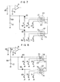
- Fig. 7 illustrates another embodiment of the present invention, in which only the related portions are depicted and the other portions which are the same as those in Fig. 6 are omitted therefrom.
- the same component is attached with the same reference numeral as used in Fig. 6.
- each voltage detecting circuit is constituted by a single diode. That is, with respect to a motor 24, the cathode of a diode 81 is connected to a transistor 18 and with respect to another motor 37, the cathode of a diode 82 is connected to the collector of a transistor 69.
- the respective anodes of the diodes 81 and 82 are connected to each other.
- a resistor 89 is connected at its one end to the positive output of a voltage source 10 and at its other end to one end of a capacitor 80.
- the junction point between the resistor 89 and the capacitor 80 is connected to one input of an error amplifier 9.
- This arrangement is a so-called low voltage detector arrangement in which one diode (81 or 82) which is connected to the transistor (18 or 69) whoes collector voltage is lower than the other is conducted, and, the voltage across the capacitor is clamped to the lowest voltage value in the conduction period of the conducted diode at its cathode.
- the variable voltage supply circuit 38 can be controlled to produce a proper output by suitably selecting the time constant determined by the resistor 89 and the capacitor 80 and voltage of the reference voltage source 8.
- each of the voltage detecting circuits can be constituted by a single diode with an advantage that the power supply system can be provided simply and inexpensively.
- Fig. 8 illustrates a further embodiment of the present invention, in which only the related portions are depicted and the other portions which are the same as those in Fig. 6 are omitted therefrom.
- the same component is attached with the same reference numeral as used in Fig. 6.
- the detection of the collector voltage of the transistors for driving each motor is performed only by a single diode.
- the respective cathodes of diodes 85 and 86 are connected to the collector of a transistor 18 for a motor 24 and the collector of a transistor 69 for a motor 37, respectively.
- the respective anodes of the diodes 85 and 86 are connected to each other.
- a resistor 90 is connected at its one end to the positive output of a voltage source 10 and at its other end to the connection between the anodes of the diodes 85 and 86 as well as one end of a resistor 84.
- the other end of the resistor 84 is connected to one end of a capacitor 83.
- the other end of the capacitor 83 is connected to the ground, that is, the negative output of the voltage source 10.
- the junction point between the resistor 84 and the capacitor 83 is connected to one input of an error amplifier 9.
- the resistor 84 and the capacitor 83 constitute a low-pass filter and, preferably, the time constant of the low-pass filter is selected to be three times or more as large as the period of the counter electromotive force induced in the motor.
- the variable voltage supply circuit 38 can be controlled to produce a proper output by suitably selecting the output voltage of the reference voltage source 8.
- a plurality of motors are supplied with power by a single commonly-provided variable voltage supply circuit, resulting in advantages that the system is superior in economy and expected to reduce power losses in the motor driving circuit with effective power saving.
Landscapes
- Engineering & Computer Science (AREA)
- Power Engineering (AREA)
- Control Of Multiple Motors (AREA)
- Control Of Motors That Do Not Use Commutators (AREA)
Applications Claiming Priority (2)
| Application Number | Priority Date | Filing Date | Title |
|---|---|---|---|
| JP57108401A JPS592594A (ja) | 1982-06-25 | 1982-06-25 | モ−タ群の電源回路 |
| JP108401/82 | 1982-06-25 |
Publications (2)
| Publication Number | Publication Date |
|---|---|
| EP0097916A2 true EP0097916A2 (de) | 1984-01-11 |
| EP0097916A3 EP0097916A3 (de) | 1984-10-17 |
Family
ID=14483817
Family Applications (1)
| Application Number | Title | Priority Date | Filing Date |
|---|---|---|---|
| EP83106107A Withdrawn EP0097916A3 (de) | 1982-06-25 | 1983-06-22 | Energieversorgung für Mehrmotorenantriebe |
Country Status (3)
| Country | Link |
|---|---|
| US (1) | US4503369A (de) |
| EP (1) | EP0097916A3 (de) |
| JP (1) | JPS592594A (de) |
Cited By (1)
| Publication number | Priority date | Publication date | Assignee | Title |
|---|---|---|---|---|
| EP0247416A1 (de) * | 1986-05-17 | 1987-12-02 | Deutsche Thomson-Brandt GmbH | Gleichlauf- und Bremssteuerung |
Families Citing this family (13)
| Publication number | Priority date | Publication date | Assignee | Title |
|---|---|---|---|---|
| DE3715939A1 (de) * | 1986-05-14 | 1987-11-19 | Matsushita Electric Industrial Co Ltd | Schaltungsanordnung zum regeln der drehzahl eines motors |
| FR2631179B1 (fr) * | 1988-05-06 | 1991-04-12 | Signaux Equip Electroniques | Dispositif pour commander au moins un moteur electrique d'asservissement avec une puissance elevee a partir d'un reseau basse tension, en particulier pour la motorisation d'une tourelle embarquee sur un char de combat |
| NL9101453A (nl) * | 1990-09-10 | 1992-04-01 | Barmag Barmer Maschf | Frequentie-omvormer. |
| US5099186A (en) * | 1990-12-31 | 1992-03-24 | General Motors Inc. | Integrated motor drive and recharge system |
| JP3060325B2 (ja) * | 1991-01-24 | 2000-07-10 | 株式会社セコー技研 | 高速直流電動機 |
| EP0989656B1 (de) * | 1998-09-24 | 2009-03-11 | Levitronix LLC | Permanentmagnetisch erregter elektrischer Drehantrieb |
| TW463455B (en) * | 2000-02-22 | 2001-11-11 | Delta Electronics Inc | Control circuit and method of multiple-motor structure |
| US7230401B2 (en) * | 2002-03-27 | 2007-06-12 | Brother Kogyo Kabushiki Kaisha | Apparatus and method for controlling an electric motor |
| US6914855B2 (en) * | 2002-09-27 | 2005-07-05 | Timex Group B.V. | Circuit for driving motor coils in stepping motors |
| JP4496779B2 (ja) * | 2004-01-09 | 2010-07-07 | 株式会社デンソー | モータの制御装置 |
| JP5413424B2 (ja) * | 2011-08-24 | 2014-02-12 | パナソニック株式会社 | モータ駆動装置およびブラシレスモータ |
| ITMI20112271A1 (it) | 2011-12-15 | 2013-06-16 | Sime Srl | Separazione di famiglie idrocarburiche o di singoli componenti via distillazioni estrattive consecutive realizzate in una sola colonna. |
| EP4449828A4 (de) | 2021-12-17 | 2025-04-09 | Exro Technologies Inc. | Artikel für einen wechselrichter und wechselrichter |
Family Cites Families (4)
| Publication number | Priority date | Publication date | Assignee | Title |
|---|---|---|---|---|
| US3911338A (en) * | 1970-06-26 | 1975-10-07 | Matsushita Electric Industrial Co Ltd | Current control circuit for a plurality of loads |
| DE2251292C3 (de) * | 1972-10-19 | 1984-03-29 | Papst-Motoren GmbH & Co KG, 7742 St Georgen | Anordnung zur Drehzahlregelung eines kollektorlosen Gleichstrommotors |
| US3866099A (en) * | 1973-08-01 | 1975-02-11 | Gen Motors Corp | Motor power supply system |
| JPS55155592A (en) * | 1979-05-18 | 1980-12-03 | Sanyo Electric Co Ltd | Synchronized operation control system for brushless motor |
-
1982
- 1982-06-25 JP JP57108401A patent/JPS592594A/ja active Pending
-
1983
- 1983-06-22 US US06/506,896 patent/US4503369A/en not_active Expired - Fee Related
- 1983-06-22 EP EP83106107A patent/EP0097916A3/de not_active Withdrawn
Cited By (1)
| Publication number | Priority date | Publication date | Assignee | Title |
|---|---|---|---|---|
| EP0247416A1 (de) * | 1986-05-17 | 1987-12-02 | Deutsche Thomson-Brandt GmbH | Gleichlauf- und Bremssteuerung |
Also Published As
| Publication number | Publication date |
|---|---|
| EP0097916A3 (de) | 1984-10-17 |
| JPS592594A (ja) | 1984-01-09 |
| US4503369A (en) | 1985-03-05 |
Similar Documents
| Publication | Publication Date | Title |
|---|---|---|
| US4503369A (en) | Power supply for plural brushless DC motors | |
| US4651067A (en) | Apparatus for driving brushless motor | |
| US5241251A (en) | Drive signal generating device | |
| US4527102A (en) | Drive system for a DC motor with reduced power loss | |
| CA1175477A (en) | Drive circuit for an alternate phase brushless dc motor | |
| KR940001751B1 (ko) | 영상기기용 카셋트 테이프의 로딩 장치 및 방법 | |
| GB2114323A (en) | Automatic control of d.c motors | |
| US3959700A (en) | Speed control device for transistor motor | |
| US4638223A (en) | Motor driving circuit | |
| US3662238A (en) | Electronically commutated motor | |
| EP0154863B1 (de) | Gerät zum Betrieb eines bürstenlosen Mehrphasenmotors | |
| US5874814A (en) | Brushless motor driven by applying varying driving signals | |
| JPS6111556B2 (de) | ||
| JPS648554B2 (de) | ||
| US3805131A (en) | Electrical drive arrangement for rewinding equipment | |
| JPS62118786A (ja) | ブラシレス直流モ−タの回転数を制御する回転数情報の発生方法および発生回路装置 | |
| KR0154960B1 (ko) | 브이 씨 알의 드럼 서보 장치 | |
| JPH0648915B2 (ja) | ブラシレスモ−タの誘起電圧検出回路 | |
| JP3108965B2 (ja) | ブラシレスモータの駆動装置 | |
| US5022604A (en) | Reel servo device for video cassette recorder in direct drive reel system | |
| KR0181025B1 (ko) | 브이씨알의 드럼모터 구동 장치 | |
| JP3065098B2 (ja) | ブラシレス直流モータ駆動回路 | |
| JPS58186388A (ja) | 直流モ−タ | |
| KR100220517B1 (ko) | 홀센서가 제거된 헤드드럼모터의 구동회로 | |
| JPS5914383A (ja) | 直流モ−タのスイツチングガバナ装置 |
Legal Events
| Date | Code | Title | Description |
|---|---|---|---|
| PUAI | Public reference made under article 153(3) epc to a published international application that has entered the european phase |
Free format text: ORIGINAL CODE: 0009012 |
|
| 17P | Request for examination filed |
Effective date: 19830728 |
|
| AK | Designated contracting states |
Designated state(s): DE FR GB |
|
| PUAL | Search report despatched |
Free format text: ORIGINAL CODE: 0009013 |
|
| AK | Designated contracting states |
Designated state(s): DE FR GB |
|
| STAA | Information on the status of an ep patent application or granted ep patent |
Free format text: STATUS: THE APPLICATION HAS BEEN WITHDRAWN |
|
| 18W | Application withdrawn |
Withdrawal date: 19861030 |
|
| RIN1 | Information on inventor provided before grant (corrected) |
Inventor name: ITO, TAKAYASU Inventor name: KOBORI, YASUNORI Inventor name: NISHIJIMA, HIDEO Inventor name: FUKUSHIMA, ISAO Inventor name: TESHIMA, TSUNEHIKO |