EP0247406A1 - Pressure cooker with a sealing gasket - Google Patents
Pressure cooker with a sealing gasket Download PDFInfo
- Publication number
- EP0247406A1 EP0247406A1 EP87106633A EP87106633A EP0247406A1 EP 0247406 A1 EP0247406 A1 EP 0247406A1 EP 87106633 A EP87106633 A EP 87106633A EP 87106633 A EP87106633 A EP 87106633A EP 0247406 A1 EP0247406 A1 EP 0247406A1
- Authority
- EP
- European Patent Office
- Prior art keywords
- container
- lid
- sealing lip
- sliding element
- pressure cooker
- Prior art date
- Legal status (The legal status is an assumption and is not a legal conclusion. Google has not performed a legal analysis and makes no representation as to the accuracy of the status listed.)
- Granted
Links
- 238000007789 sealing Methods 0.000 title claims abstract description 53
- 229920001971 elastomer Polymers 0.000 claims description 2
- 239000000806 elastomer Substances 0.000 claims description 2
- 239000004033 plastic Substances 0.000 claims description 2
- 238000003825 pressing Methods 0.000 claims description 2
- 229920002379 silicone rubber Polymers 0.000 claims description 2
- 239000004945 silicone rubber Substances 0.000 claims description 2
- 229910001220 stainless steel Inorganic materials 0.000 claims 1
- 239000010935 stainless steel Substances 0.000 claims 1
- 230000000994 depressogenic effect Effects 0.000 description 6
- 238000010411 cooking Methods 0.000 description 5
- 239000000463 material Substances 0.000 description 5
- 238000000034 method Methods 0.000 description 3
- 239000002184 metal Substances 0.000 description 2
- 238000004026 adhesive bonding Methods 0.000 description 1
- 230000004888 barrier function Effects 0.000 description 1
- 239000011324 bead Substances 0.000 description 1
- 230000015572 biosynthetic process Effects 0.000 description 1
- 230000000295 complement effect Effects 0.000 description 1
- 230000000694 effects Effects 0.000 description 1
- 238000005538 encapsulation Methods 0.000 description 1
- 230000003993 interaction Effects 0.000 description 1
- 238000004519 manufacturing process Methods 0.000 description 1
- 229920003051 synthetic elastomer Polymers 0.000 description 1
- 239000005061 synthetic rubber Substances 0.000 description 1
- 238000004073 vulcanization Methods 0.000 description 1
Images


Classifications
-
- A—HUMAN NECESSITIES
- A47—FURNITURE; DOMESTIC ARTICLES OR APPLIANCES; COFFEE MILLS; SPICE MILLS; SUCTION CLEANERS IN GENERAL
- A47J—KITCHEN EQUIPMENT; COFFEE MILLS; SPICE MILLS; APPARATUS FOR MAKING BEVERAGES
- A47J27/00—Cooking-vessels
- A47J27/08—Pressure-cookers; Lids or locking devices specially adapted therefor
- A47J27/09—Safety devices
-
- A—HUMAN NECESSITIES
- A47—FURNITURE; DOMESTIC ARTICLES OR APPLIANCES; COFFEE MILLS; SPICE MILLS; SUCTION CLEANERS IN GENERAL
- A47J—KITCHEN EQUIPMENT; COFFEE MILLS; SPICE MILLS; APPARATUS FOR MAKING BEVERAGES
- A47J27/00—Cooking-vessels
- A47J27/08—Pressure-cookers; Lids or locking devices specially adapted therefor
- A47J27/0804—Locking devices
- A47J27/0806—Locking devices of the bayonet-type
-
- A—HUMAN NECESSITIES
- A47—FURNITURE; DOMESTIC ARTICLES OR APPLIANCES; COFFEE MILLS; SPICE MILLS; SUCTION CLEANERS IN GENERAL
- A47J—KITCHEN EQUIPMENT; COFFEE MILLS; SPICE MILLS; APPARATUS FOR MAKING BEVERAGES
- A47J27/00—Cooking-vessels
- A47J27/08—Pressure-cookers; Lids or locking devices specially adapted therefor
- A47J27/09—Safety devices
- A47J27/092—Devices for automatically releasing pressure before opening
Definitions
- the invention relates to a pressure cooker.
- the seal is provided with radial ribs which have no function in the closed state, but when the cover is pressed down, the seal is lifted from the container or from the cover like a lever bearing. The overpressure can be released with one hand.
- the object of the invention is to provide such a one-handed steam pressure cooker, the un is complex to produce, is subject to less wear and allows complete and rapid release of the excess pressure before opening the pot.
- the pressure cooker according to the invention has the features defined in claim 1.
- the pressure cooker according to the invention can be produced without great effort because of its simple structure. Before opening, the sliding element lifts the sealing lip off the lid or container, thus allowing the excess pressure to escape quickly. Sliding element and sealing lip are hardly stressed in their interaction and are only distributed over a larger contact area, so that the A b use remains low. In the case of a seal with two sealing lips that rest on the lid or on the container, the sliding element can be combined with one of the two, as desired.
- the pressure cooker can be cylindrical or with a rectangular base.
- the sliding element facilitates the lid movement and prevents the sealing lip, which is then completely lifted, from wearing out.
- Figures 1 to 6 show an open-topped cookware container 1 with a continuous container rim 9, from the circumference of which segment-like edge projections 4 project radially outwards.
- locks 5 and stops 6 alternately extend downward and radially outward below the container edge 9 and close to the outer edge of the edge projections 4.
- the radial extent of the locks 5 and stops 6 is essentially the same (FIGS. 1, 3 and 5); the locks 5, however, extend less far downward than the stops 6.
- the locks 5 and stops 6 each lie on the circumferential ends of the edge projections 4. They form a closing device, together with complementary devices of the cover described later.
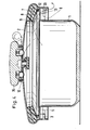
- the lid edge 10 of a lid 2 projects beyond the cooking material container 1 on all sides.
- the lid 2 bulges slightly downwards to the lid edge 10 and then inwards to form an inwardly open channel for receiving the seal 11 to be described.
- annular straight web area 33 extends downward from the lid edge 10.
- the lid edge projections 3 protrude radially inward from the web area 33 and form circular disk segments which are complementarily similar to the container edge projections 4. If each edge of the lid projection 3 in a andlücke R 13 is between two container edge projections 4 (Fig. 3), which cover edge projections 3 may pass downwardly between the container edge 4 projections.
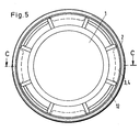
- the cover 2 is first, as shown in F ig. 5 and 6 ge shows, placed in any position on the edge of the food container 1.
- the lid edge protrusions 3 rest on the top of the container edge protrusions 4 facing away from the bottom of the cooking material container 1.
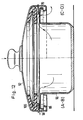
- the lid 2 is turned until the lid edge projections lie in the edge gaps 13 (FIG. 3) and then pressed down (FIG. 4).
- the cover edge projections 3 lie laterally on the stops 6.
- FIGS. 1 and 2 when the lid is released, it can move upwards to a limited extent until the lid edge projections 3 come into contact with the container edge projections 4 (FIG. 2). This is the operating position of the locking device of the pressure cooker.
- the cover 2 has a seal 11 which is radially inward V-shaped in cross section and thus forms two sealing lips 7, 8.
- the seal 11 extends as a closed, essentially circular profile over the entire circumference of the lid edge 10. Its one, upper sealing lip 8 lies flat against the underside of the lid 2, while its other, lower sealing lip 7 with the lid 2 removed from the lid edge 10 protrudes freely inwards and downwards. The free end of this lower sealing lip 7 rests on the container rim 9 of the cookware container 1 when the lid 2 is attached and seals the lid 2 from the cookware container 1.
- a closed ring as a sliding element 12 made of a material which, with the container 1 or cover 2, results in a sliding pairing with the lowest possible coefficient of friction, for example made of metal or hard plastic.
- the seal consists for example of an NBR elastomer or synthetic rubber, such as silicone rubber.
- the outer diameter of the sliding element is almost as large as the inner diameter of the web area 33. As a result, the sliding element 12 cannot slip out of its position between the sealing lip 7, the web area 33 and the lid edge projections 3.
- the spring force of the seal 11 would twist of the lid 2 significantly more difficult if the sealing lip 7 would abut the container rim 9.
- the much lower friction between the sliding element 12 and the container rim 9 makes it much easier to rotate the lid 2; since, in addition, the sealing lip 7 is pivoted completely away from the container edge 9, the friction between the sliding element 12 and the container edge 9 is the only counterforce when the cover 2 is rotated.
- the sliding element 12 Because of the relatively high rigidity of the sliding element 12, it can support the lower sealing lip 7 in the region of the edge gaps 13 without having to be supported on the underside itself.
- the sliding element 12 therefore helps to prevent excessive deformation of the sealing lip 7 in this area, which could lead to the pressure cooker becoming leaky.
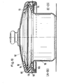
- a safety valve arranged in the knob handle 35 of the cover 2 limits the excess pressure and comprises a valve opening 40 which forms a seat for a valve body 15.
- the valve body 15 is displaced in a vertical blind bore of the knob handle 35 Lich guided and is urged by a spring 39 to the valve opening 40 of the cover 2.
- the spring force of the spring 39 is matched to the desired operating pressure.
- the button handle 35 is provided on the underside with bores 42 into which driver pins 41 fastened to the cover 2 engage. These bores 42, just like the bores accommodating the valve body 15, are arranged eccentrically to the central axis of the knob handle 35.
- the extension 16 of the knob handle 35 forms a vapor pressure relief valve with the underside of the cover 2, which can be opened by pressing the knob handle 35.
- the button handle 35 When the cooking process is finished, the button handle 35 is depressed. Part of the overpressure initially escapes through the drain valve 16 (FIG. 4). When the button handle 35 is pressed further, the entire cover 2 is pressed down. The lower sealing lip 7 is pivoted upward like a lever about its point of contact on the sliding element 12; the remaining overpressure can escape through the marginal gaps 13, 14. Since a very large cross-section is available for this, measured at the drain valve, the pressure cooker quickly becomes completely depressurized. The cover 2 can subsequently be turned and unlocked.
- FIGS. 7 and 8 A second preferred embodiment of the pressure cooker is shown in FIGS. 7 and 8.
- the cookware container 1 has a circumferential, smooth container edge 17.
- a cover 2 comprises a hood 18 forming its main body. On its outer circumference, the hood 18 has a groove 32 which is open at the top and approximately rectangular in cross section and which is surrounded radially outwards by a second groove 34 which is open at the bottom.
- a cover ring 25 extends in a radially outward direction over both grooves 32, 34.
- clamps 19 are provided which are movable with respect to the cover 2 in its radial as well as in the circumferential direction.
- slots 27 of the brackets 19 are sliding blocks 26, which are held between the bottom of the second groove 34 and the cover ring 25.
- a horizontal locking area 29 attaches to the lower edge of the clips 19.
- a web 36 engages behind the outer edge of the container edge 17 in the locked position of the lid.
- the locking region 29 has a slot 24 through which a finger 23 of the frame ring 20 extends. As a result, the bracket 19 can only move radially.
- the seal 11 rests with an upper sealing lip 21 on the underside of the hood 18.
- a hood opening 31 is provided radially outward from the contact point between the upper sealing lip 21 and this area.
- the sliding element 12 is held in its position by the radially inward wall and the bottom of the second groove 34, by the frame ring 20 and the upper side of the upper sealing lip 21.
- the bracket 19 is in its most radially inwardly displaced position, the top of its locking area 29 is located on the lower edge 30 of the web extending downward on the outer edge of the container edge 17.
- the lid 2 Due to the internal pressure and the seal 11, the lid 2 is pushed away from the food container 1; this movement is limited by the engagement of the latch area 29 and the lower edge 30.
- the pressure cooker is first partially depressurized, as in the first embodiment.
- the sliding element 12 lever the upper sealing lip 21 off the hood 18, as shown in FIG. 8.
- the residual internal pressure by the H aubenöff- can voltages 31 to escape.
- the frame ring 20 lying flat against it is also not rotated.
- the fingers 23 prevent the clamps 19 from rotating relative to the cookware container 1, so that overall there is a rotation of the hood and cover ring 25 relative to the entirety of the cookware container 1, seal 11, frame ring 20, clamps 19 and sliding element 12.
- the sliding blocks 26 slide in the slots 27 and push the clamps 19 outwards.
- the upper edges 28 of the webs 36 of the clamps 19 are in engagement with the lower edges 30 of the web on the container edge 17.
- the lid 2 is pulled so far towards the food container 1 that the upper sealing lip 21 is in its raised position and no pressure can build up in the pot.
- the edges 28, 30 therefore act like the locks 5 of the first embodiment.
- a third preferred embodiment comprises a rectangular cookware container 50 with a rectangular lid 52.
- the lid 52 can be pushed onto or pushed off the cookware container 50 in the longitudinal direction thereof and is held on the container by a horizontal web 54 which engages under the container edge 56.
- Such a pot is known for example from DE-PS 28 01 173.
- a seal 60 is clamped to the cover 52 by a support element 72 which lies between two sealing lips 62, 64.
- Under the lower sealing lip 64 is a sliding element 100 with side lugs 68, which protrude outward through slots 58 in the edge of the cover 52 and hold the sliding element 100.
- Seal 60 and sliding element 100 follow the rectangular contour of the lid 52. Material rigidity and holding of the sliding element 100 by the lugs 68 are selected so that the lower sealing lip 64 can rest on the container edge 56 when the lid is pushed on, but on the other hand a slight snapping of the lid 52 onto the container 50 can be done.
- the sealing function of the pressure cooker during operation corresponds exactly to that already described. In the operating state, the contact of the lower sealing lip 64 on the container edge 56 prevents the internal pressure from escaping.
- the slider 100 serves as a lever bearing.
- the residual steam can escape through openings 70 in the container edge 56 (FIG. 12).
- the sliding element 100 is also provided on its side facing away from the lower sealing lip 64 with recesses 66 which, together with the slots 58, form a further possibility for the steam to escape.
- the lid 52 can then be completely pushed off the cooking material container 50, as shown in FIGS. 11 and 12.
- the sliding element can be integrated into the seal, for example by Gluing, vulcanization or partial encapsulation or even one-piece manufacture. Furthermore, it is possible to replace the sliding element with a functionally corresponding, lever-bearing-shaped formation (bead) on the lid or container edge.
Landscapes
- Engineering & Computer Science (AREA)
- Food Science & Technology (AREA)
- Cookers (AREA)
- Pressure Vessels And Lids Thereof (AREA)
Abstract
Die Erfindung betrifft einen Dampfdruckkochtopf aus einem Kochgut aufnehmenden Behälter (1), einem darauf aufsetzbaren Deckel (2) mit Sicherheitsventil, einer Behälter und Deckel im Schließzustand aneinander festlegenden Schließeinrichtung und einer zwischen Deckel und Behälter angeordneten, im Schließzustand den Topfinnenraum gegen Druckabfall sichernden Dichtung, wobei eine radial einwärtsweisende Dichtlippe (7,8) der Dichtung am Deckel oder am Behälter anliegt, die beim Niederdrücken des Deckels in Richtung auf den Behälter aus der dichtenden Anlage am Deckel oder am Behälter abhebt und wobei der Deckel oder der Behälter beim anschließenden Bewegen des Deckels in die Öffnungsstellung eine Relativbewegung zur Dichtlippe ausführt. Zwischen der Dichtlippe und dem Deckel oder dem Behälter ist ein Gleitelement (12) radial außerhalb des Randes der Dichtlippe angeordnet, welches als Hebellager für die Abhebbewegung der Dichtlippe wirkt.The invention relates to a pressure cooker made of a container (1) that holds the food to be cooked, a lid (2) with a safety valve that can be placed thereon, a container and lid that locks one another in the closed state, and a seal that is arranged between the lid and the container and in the closed state seals the interior of the pot against pressure drop, wherein a radially inward-pointing sealing lip (7, 8) of the seal rests on the cover or on the container, which lifts off when the cover is pressed towards the container from the sealing contact on the cover or on the container, and wherein the cover or container is subsequently moved Lid performs a relative movement to the sealing lip in the open position. Between the sealing lip and the lid or the container, a sliding element (12) is arranged radially outside the edge of the sealing lip, which acts as a lever bearing for the lifting movement of the sealing lip.
Description
Die Erfindung betrifft einen Dampfdruckkochtopf.The invention relates to a pressure cooker.
Im Inneren eines Dampfdruckkochtopfes besteht nach seiner Erhitzung ein Überdruck. Bei modernen Dampfdruckkochtöpfen kann mit einer Hand sowohl der Überdruck (durch öffnen der Dichtung) gefahrlos abgelassen, als auch der Deckel entriegelt und abgehoben werden.There is an overpressure inside a pressure cooker after it has been heated. With modern pressure cookers, the overpressure (by opening the seal) can be safely released with one hand, and the lid can be unlocked and lifted off.
Bei dem aus der US-PS 4 434 909 bekannten Dampfdruckkochtopf ist die Dichtung mit radialen Rippen versehen, die im Schließzustand funktionslos sind, aber beim Niederdrücken des Deckels hebellagerartig die Dichtung vom Behälter bzw. vom Deckel abheben. So kann der Überdruck einhändig abgelassen werden.In the steam pressure cooker known from US Pat. No. 4,434,909, the seal is provided with radial ribs which have no function in the closed state, but when the cover is pressed down, the seal is lifted from the container or from the cover like a lever bearing. The overpressure can be released with one hand.
Nachteilig ist bei diesem bekannten Dampfdruckkochtopf, daß die Verdrehung des niedergedrückten Deckels erheblich Kraft erfordert, weil dabei die Radialrippen, gegen den Behälter bzw. den Deckel gepreßt, senkrecht zu ihrer Längserstreckung gleiten müssen. Dies erschwert die Bedienung erheblich. Auch unterliegt die Dichtlippe dabei der Abnutzung und möglicherweise Beschädigung, da sich die Belastung auf kleine Auflageflächen konzentriert.The disadvantage of this known pressure cooker is that the rotation of the depressed lid requires considerable force, because the radial ribs, pressed against the container or the lid, have to slide perpendicular to their longitudinal extent. This makes operation considerably more difficult. The sealing lip is also subject to wear and possibly damage, since the load is concentrated on small contact surfaces.
Aufgabe der Erfindung ist es, einen solchen einhändig bedienbaren Dampfdruckkochtopf zu schaffen, der unaufwendig herzustellen ist, geringerer Abnutzung unterliegt und vollständiges wie rasches Ablassen des Überdrucks vor öffnung des Topfes erlaubt.The object of the invention is to provide such a one-handed steam pressure cooker, the un is complex to produce, is subject to less wear and allows complete and rapid release of the excess pressure before opening the pot.
Zur Lösung dieser Aufgabe weist der Dampfdruckkochtopf erfindungsgemäß die im Patentanspruch 1 definierten Merkmale auf.To achieve this object, the pressure cooker according to the invention has the features defined in
Vorteilhafte Ausgestaltungen sind in den Unteransprüchen beschrieben.Advantageous refinements are described in the subclaims.
Der erfindungsgemäße Dampfdruckkochtopf ist wegen seines einfachen Aufbaus ohne großen Aufwand herstellbar. Das Gleitelement hebt vor dem öffnen die Dichtlippe vom Deckel bzw. vom Behälter ab und ermöglicht so ein rasches Entweichen des Überdruckes. Gleitelement und Dichtlippe werden bei ihrem Zusammenwirken kaum und nur über eine größere Berührungsfläche verteilt beansprucht, so daß die Ab-nutzung gering bleibt. Bei einer Dichtung mit zwei Dichtlippen, die am Deckel bzw. am Behälter anliegen, kann das Gleitelement nach Wahl mit einer von beiden kombiniert werden. Der Dampfdruckkochtopf kann zylindrisch oder mit rechteckiger Grundfläche ausgebildet werden.The pressure cooker according to the invention can be produced without great effort because of its simple structure. Before opening, the sliding element lifts the sealing lip off the lid or container, thus allowing the excess pressure to escape quickly. Sliding element and sealing lip are hardly stressed in their interaction and are only distributed over a larger contact area, so that the A b use remains low. In the case of a seal with two sealing lips that rest on the lid or on the container, the sliding element can be combined with one of the two, as desired. The pressure cooker can be cylindrical or with a rectangular base.
Gleich, ob die Trennung von Deckel und Behälter durch eine Verdrehung des Deckels gegenüber einem zylindrischen Behälter oder durch horizontales Abschieben des Deckels von einem rechteckigen Behälter erfolgt, erleichtert das Gleitelement die Deckelbewegung und vermeidet eine Abnutzung der - dann vollständig abgehobenen - Dichtlippe.Regardless of whether the lid and container are separated by twisting the lid relative to a cylindrical container or by horizontally pushing the lid off a rectangular container, the sliding element facilitates the lid movement and prevents the sealing lip, which is then completely lifted, from wearing out.
Im folgenden werden bevorzugte Ausführungsformen der Erfindung anhand der beigefügten Zeichnungen erläutert.In the following preferred embodiments of the invention will be explained with reference to the accompanying drawings.
Es zeigen:
- Fig. 1 eine erste Ausführungsform des Dampfdruckkochtopfes von unten in verriegeltem Zustand;
- Fig. 2 einen Vertikalschnitt des Dampfdruckkochtopfes entlang der Linie A-A in
Figur 1; - Fig. 3 den Dampfdruckkochtopf von unten in entriegeltem Zustand;
- Fig. 4 einen Vertikalschnitt entlang der Linie B-B in
Figur 3 bei niedergedrücktem Deckel; - Fig. 5 den Dampfdruckkochtopf von unten bei lose aufgelegtem Deckel;
- Fig. 6 einen Vertikalschnitt entlang der Linie C-C in Figur.5;
- Fig. 7 einen weggebrochenen Teilschnitt einer zweiten Ausführungsform des Dampfdruckkochtopfes in verriegeltem Zustand;
- Fig. 8 einen entsprechenden Teilschnitt des entriegelten Dampfdruckkochtopfes bei niedergedrücktem Deckel;
- Fig. 9 eine Ansicht einer dritten Ausführungsform des Dampfdruckkochtopfes von unten in geschlossenem Zustand;
- Fig. 10 Teilschnitte gemäß den Linien A-B und C-D in Fig. 9;
- Fig. 11 eine Ansicht entsprechend Fig. 9 bei teilweise abgeschobenem Deckel und
- Fig. 12 Teilschnitte gemäß den Linien A-B und C-D in Fig. 11.
- Figure 1 shows a first embodiment of the pressure cooker from below in the locked state.
- 2 shows a vertical section of the pressure cooker along the line AA in FIG. 1;
- F ig. 3 the pressure cooker from below in the unlocked state;
- 4 shows a vertical section along the line BB in FIG. 3 with the cover pressed down;
- Figure 5 shows the pressure cooker from below with the lid loosely placed.
- F ig. 6 shows a vertical section along the line CC in FIG. 5;
- 7 shows a broken-away partial section of a second embodiment of the pressure cooker in the locked state;
- 8 shows a corresponding partial section of the unlocked pressure cooker with the lid depressed;
- 9 shows a view of a third embodiment of the pressure cooker from below in the closed state;
- Fig. 10 are partial sections according to lines ig AB and CD in F. 9;
- Fig. 11 is a view corresponding to FIG. 9 with the cover partially pushed off and
- 12 shows partial sections along lines AB and CD in FIG. 11.
Figuren 1 bis 6 zeigen einen oben offenen Kochgutbehälter 1 mit durchgehendem Behälterrand 9, von dessen Umfang segmentartige Randvorsprünge 4 radial auswärts vorspringen.Figures 1 to 6 show an open-
Über den Umfang verteilt erstrecken sich unterhalb des Behälterrandes 9 alternierend Sperren 5 und Anschläge 6 abwärts und radial auswärts bis nahe der Außenkante der Randvorsprünge 4. Die radiale Erstreckung der Sperren 5 und Anschläge 6 ist im wesentlichen gleich (Figuren 1, 3 und 5); die Sperren 5 erstrecken sich aber weniger weit abwärts als die Anschläge 6.Distributed over the circumference, locks 5 and stops 6 alternately extend downward and radially outward below the
Die Sperren 5 und Anschläge 6 liegen jeweils an den Umfangsenden der Randvorsprünge 4. Sie bilden, zusammen mit später beschriebenen komplementären Einrichtungen des Deckels, eine Schließeinrichtung.The
Der Deckelrand 10 eines Deckels 2 (Figuren 2, 4 und 6) ragt allseitig über den Kochgutbehälter 1 hinaus. Der Deckel 2 wölbt sich auswärts leicht abwärts bis zum Deckelrand 10 und dann einwärts zur Bildung einer einwärts offenen Rinne zur Aufnahme der noch zu beschreibenden Dichtung 11.The
Unterhalb des einwärts gewölbten Bereichs des Deckelrandes 10 erstreckt sich ein ringartiger gerader Stegbereich 33 abwärts vom Deckelrand 10.Below the inwardly curved area of the
Vom Stegbereich 33 stehen Deckelrandvorsprünge 3 radial einwärts vor und bilden Kreisscheibensegmente, die den Behälterrandvorsprüngen 4 komplementär ähnlich sind. Wenn jeder Deckelrandvorsprung 3 in einer Randlücke 13 zwischen zwei Behälterrandvorsprüngen 4 liegt (Fig. 3), können die Deckelrandvorsprünge 3 abwärts zwischen den Behälterrandvorsprüngen 4 hindurchtreten.The
Beim Niederdrücken des Deckels 2 werden dessen Randvorsprünge 3 über die Unterkanten der Sperren 5 hinaus bewegt, so daß der Deckel 2 gegenüber dem Kochgutbehälter 1 verdrehbar ist. Auf der linken Seite in Fig. 4 ist erkennbar, daß dann die Deckelrandvorsprünge 3 mit ihrer Oberseite an der Unterseite der Sperren 5 anliegen. Auf der rechten Seite der Figur ist erkennbar, daß die gegenüber den Sperren 5 größere Abwärtserstreckung der Anschläge 6 die Verdrehung des Deckels 2 begrenzt.Upon depression of the
Der Deckel 2 wird zunächst, wie in Fig. 5 und 6 gezeigt, in beliebiger Stellung auf den Rand des Kochgutbehälters 1 aufgelegt. Die Deckelrandvorsprünge 3 liegen auf der vom Boden des Kochgutbehälters 1 abgewandten Oberseite der Behälterrandvorsprünge 4 auf. Jetzt wird der Deckel 2 verdreht, bis die Deckelrandvorsprünge in den Randlücken 13 liegen (Fig. 3) und dann niedergedrückt (Fig. 4). Dann wird weiter verdreht, bis die Deckelrandvorsprünge 3 seitlich an den Anschlägen 6 anliegen. Wie Fig. 1 und 2 zeigen, kann sich beim Loslassen der Deckel begrenzt aufwärts bewegen, bis die Deckelrandvorsprünge 3 an den Behälterrandvorsprüngen 4 in Anlage kommen (Fig. 2). Dies ist die Betriebsstellung der Schließeinrichtung des Dampfdruckkochtopfes .The
Zur Entriegelung des Deckels 2 wird der soeben beschriebene Vorgang umgekehrt durchgeführt.To unlock the
Der Deckel 2 weist eine Dichtung 11 auf, die - radial einwärts - im Querschnitt V-förmig ist und so zwei Dichtlippen 7, 8 bildet. Die Dichtung 11 erstreckt sich als geschlossenes, im wesentlichen kreisförmiges Profil über den gesamten Umfang des Deckelrandes 10. Ihre eine, obere Dichtlippe 8 liegt flächig an der Unterseite des Deckels 2 an, während ihre andere, untere Dichtlippe 7 bei abgenommenem Deckel 2 vom Deckelrand 10 her einwärts und abwärts geneigt frei vorsteht. Das freie Ende dieser unteren Dichtlippe 7 liegt bei aufgesetztem Deckel 2 auf dem Behälterrand 9 des Kochgutbehälters 1 auf und dichtet den Deckel 2 gegenüber dem Kochgutbehälter 1 ab.The
Unterhalb der unteren Dichtlippe 7 liegt als Gleitelement 12 ein geschlossener Ring aus einem Werkstoff, welcher mit dem Behälter 1 bzw. Deckel 2 eine Gleitpaarung von möglichst geringem Reibbeiwert ergibt, beispielsweise aus Metall oder aus hartem Kunststoff. Die Dichtung besteht beispielsweise aus einem NBR-Elastomeren oder Synthesekautschuk, etwa Silikonkautschuk.Below the
Der Gleitelement-Außendurchmesser ist fast so groß wie der Innendurchmesser des Stegbereichs 33. Dadurch kann das Gleitelement 12 aus seiner Stellung zwischen Dichtlippe 7, Stegbereich 33 und Deckelrandvorsprüngen 3 nicht herausrutschen.The outer diameter of the sliding element is almost as large as the inner diameter of the
Wird der beispielsweise gemäß Figuren 5 und 6 locker aufgelegte Deckel in die in Figuren 3 und 4 gezeigte Stellung gebracht, in welcher die Behälterrandvorsprünge 4 in die Randlücken 14 des Deckelrandes 10 eintreten, gerät das Gleitelement 12 in Berührung mit den Behälterrandvorsprüngen 4. Beim Niederdrücken des Deckels 2 wird es von diesen gehalten und aus seiner Anlage an den Deckelrandvorsprüngen 3 abgehoben.If, for example, according to FIGS. 5 and 6, the lid is placed loosely in the position shown in FIGS. 3 and 4, in which the container edge projections 4 enter the
Durch die hebellagerartige Relativstellung des Gleitelementes 12 zur Unterseite der unteren Dichtlippe 7 wird die Dichtlippe 7 beim Niederdrücken des Deckels 2 hochgeschwenkt (Fig. 4). Diese Bewegung der Dichtlippe 7 kann bis zur Anlage an der Unterseite der oberen Dichtlippe 8 gehen.Due to the lever bearing-like relative position of the sliding
Die Federkraft der Dichtung 11 würde das Verdrehen des Deckels 2 wesentlich erschweren, wenn die Dichtlippe 7 dabei am Behälterrand 9 anläge. Die wesentlich geringere Reibung zwischen dem Gleitelement 12 und dem Behälterrand 9 erleichtert die Drehung des Deckels 2 wesentlich; da zudem die Dichtlippe 7 vollständig vom Behälterrand 9 weggeschwenkt wird, ist die Reibung zwischen dem Gleitelement 12 und dem Behälterrand 9 die einzige Gegenkraft beim Verdrehen des Deckels 2.The spring force of the
Aufgrund der relativ hohen Steifheit des Gleitelementes 12 kann dieses im Bereich der Randlücken 13 die untere Dichtlippe 7 abstützen, ohne selbst unterseitig abgestützt werden zu müssen. Das Gleitelement 12 trägt daher dazu bei, eine übermäßige Deformierung der Dichtlippe 7 in diesem Bereich zu verhindern, die zum Undichtwerden des Dampfdruckkochtopfes führen könnte.Because of the relatively high rigidity of the sliding
Bei Überdruck im Dampfdruckkochtopf wird die Dichtlippe 7 so stark gegen den Behälterrand 9 gepreßt, daß, zusammen mit der Druckeinwirkung auf die Unterseite des Deckels 2 und der verdrehungshindernden Wirkung der Sperren 5 und Anschläge 6, eine Verdrehung des Deckels 2 bei anstehendem Überdruck unmöglich ist.In the event of overpressure in the pressure cooker, the sealing
Ein im Knopfgriff 35 des Deckels 2 angeordnetes Sicherheitsventil begrenzt den Überdruck und umfaßt eine Ventilöffnung 40, die einen Sitz für einen Ventilkörper 15 bildet. Der Ventilkörper 15 ist in einer vertikalen Sackbohrung des Knopfgriffes 35 verschieblich geführt und wird von einer Feder 39 zur Ventilöffnung 40 des Deckels 2 hingedrängt. Die Federkraft der Feder 39 ist auf den gewünschten Betriebs-Überdruck abgestimmt.A safety valve arranged in the knob handle 35 of the
Der Knopfgriff 35 ist unterseitig mit Bohrungen 42 versehen, in die am Deckel 2 befestigte Mitnehmerzapfen 41 eingreifen. Diese Bohrungen 42 sind, genau wie die den Ventilkörper 15 aufnehmenden Bohrungen, exzentrisch zur Mittelachse des Knopfgriffes 35 angeordnet.The button handle 35 is provided on the underside with bores 42 into which driver pins 41 fastened to the
Zentrisch zur Mittelachse des Knopfgriffes 35 trägt diese einen Fortsatz 16, der durch eine mittige Öffnung des Deckels 2 ragt. Unter Zwischenschaltung eines geeigneten Dichtringes bildet der Fortsatz 16 des Knopfgriffes 35 mit der Unterseite des Deckels 2 ein Dampfdruck-Ablaßventil, welches durch Drücken auf den Knopfgriff 35 geöffnet werden kann.Centrally to the central axis of the
Ist der Kochvorgang beendet, wird der Knopfgriff 35 niedergedrückt. Dabei entweicht zunächst ein Teil des Überdruckes durch das Ablaßventil 16 (Figur 4). Bei weiterem Druck auf den Knopfgriff 35 wird der ganze Deckel 2 niedergedrückt. Dabei wird die untere Dichtlippe 7 hebelartig um ihren Auflagepunkt am Gleitelement 12 aufwärts geschwenkt; der restliche Überdruck kann durch die Randlücken 13, 14 entweichen. Da hierfür ein, gemessen am Ablaßventil, sehr großer Querschnitt zur Verfügung steht, wird der Dampfdruckkochtopf sehr schnell völlig drucklos. Nachfolgend kann der Deckel 2 verdreht und entriegelt werden.When the cooking process is finished, the button handle 35 is depressed. Part of the overpressure initially escapes through the drain valve 16 (FIG. 4). When the button handle 35 is pressed further, the
Eine zweite bevorzugte Ausführungsform des Dampfdruckkochtopfes ist in Figuren 7 und 8 gezeigt. Der Kochgutbehälter 1 weist einen umlaufenden, glatten Behälterrand 17 auf. Ein Deckel 2 umfaßt eine seinen Hauptkörper bildende Haube 18. An ihrem Außenumfang weist die Haube 18 eine nach oben offene, im Querschnitt etwa rechteckige Nut 32 auf, die von einer nach unten offenen zweiten Nut 34 radial auswärts umschlossen wird. Am Außenrand des Deckels 2 liegt ein Rahmenring 20 in Form eines senkrechten, zum Ring geschlossenen Blechstreifens mit einer in dessen Höhenmitte eingeprägten, radial auswärts gewölbten Ringnut zur Halterung des Außenumfanges einer Dichtung 11, die der bereits beschriebenen entspricht. Über die Unterkante des Rahmenringes 20 stehen Finger 23 abwärts vor.A second preferred embodiment of the pressure cooker is shown in FIGS. 7 and 8. The
Auf der Oberseite der Haube 18 erstreckt sich unverschieblich ein Abdeckring 25 in radial auswärtiger Richtung über beide Nuten 32, 34 hinweg.On the top of the
Zwischen dem Abdeckring 25 und der Haube 18 sind, in Umfangsrichtung des Deckels 2 voneinander beabstandet, Klammern 19 vorgesehen, die gegenüber dem Deckel 2 in dessen radialer, wie auch in Umfangsrichtung beweglich sind.Between the
In Schlitzen 27 der Klammern 19 liegen Gleitsteine 26, die zwischen dem Boden der zweiten Nut 34 und dem Abdeckring 25 gehalten sind. An der Unterkante der Klammern 19 setzt ein horizontaler Riegelbereich 29 an.In
Am radial einwärtigen Ende des Riegelbereichs 29 hintergreift ein Steg 36 in der Verriegelungsstellung des Deckels den Außenrand des Behälterrandes 17.At the radially inward end of the locking
Der Riegelbereich 29 weist einen Schlitz 24 auf, durch den sich ein Finger 23 des Rahmenringes 20 erstreckt. Dadurch kann sich die Klammer 19 nur radial verschieben.The locking
Wie insbesondere Figur 7 zeigt, liegt die Dichtung 11, mit einer oberen Dichtlippe 21 an der Unterseite der Haube 18 an. Radial auswärts von der Kontaktstelle zwischen der oberen Dichtlippe 21 und diesem Bereich ist eine Haubenöffnung 31 vorgesehen. In der zweiten Nut 34 liegt ein Gleitelement 12. Das Gleitelement 12 wird durch die radial einwärtige Wand und den Boden der zweiten Nut 34, durch den Rahmenring 20 und die Oberseite der oberen Dichtlippe 21 in seiner Stellung gehalten.As shown in FIG. 7 in particular, the
Im Betriebszustand steht ein innerer Überdruck an, dessen Entweichen die Dichtung 11 verhindert. Die obere Dichtlippe 21 wird gegen eine übermäßige Verformung durch das Gleitelement 12 abgestützt, die untere Dichtlippe 22 durch die Schrägneigung des Behälterrandes 17.In the operating state, there is an internal excess pressure, the escape of which prevents the
Die Klammer 19 liegt in ihrer am meisten radial einwärts verschobenen Stellung, die Oberseite ihres Riegelbereichs 29 liegt an der Unterkante 30 des sich am Außenrand des Behälterrandes 17 abwärts erstreckenden Steges.The
Durch den Innendruck sowie durch die Dichtung 11 wird der Deckel 2 vom Kochgutbehälter 1 weggedrängt; diese Bewegung wird durch die Anlage von Riegelbereich 29 und Unterkante 30 begrenzt.Due to the internal pressure and the
Nach Beendigung des Garvorganges wird der Dampfdruckkochtopf zunächst wie bei der ersten Ausführungsform teilweise drucklos gemacht. Beim weiteren Niederdrücken hebelt das Gleitelement 12 die obere Dichtlippe 21 von der Haube 18 ab, wie Figur 8 zeigt. So kann der restliche Innendruck durch die Haubenöff- nungen 31 entweichen.After the end of the cooking process, the pressure cooker is first partially depressurized, as in the first embodiment. When depressed further, the sliding
Beim nachfolgenden Drehen des Deckels 2 gegenüber dem Kochgutbehälter 1 gleitet die Haube 18 auf dem Gleitelement 12, welches dieser Gleitbewegung nur eine geringe Reibkraft entgegensetzt. Hingegen verbleibt die Dichtung 11 wegen der größeren Reibhaftung zwischen der unteren Dichtlippe 22 und dem Behälterrand 17 diesem gegenüber unverdreht und hält ihrerseits das Gleitelement 12 fest.When the
Da die Dichtung 11 nicht verdreht wird, wird auch der flächig an ihn anliegende Rahmenring 20 nicht mit verdreht. Die Finger 23 hindern die Klammern 19 an einer Verdrehung gegenüber dem Kochgutbehälter 1, so daß sich insgesamt eine Verdrehung von Haube und Abdeckring 25 gegenüber der Gesamtheit von Kochgutbehälter 1, Dichtung 11, Rahmenring 20, Klammern 19 und Gleitelement 12 ergibt. Bei dieser Relativbewegung gleiten die Gleitsteine 26 in den Schlitzen 27 und schieben die Klammern 19 auswärts.Since the
Jetzt kann die gesamte Dichtungsanordnung zusammen mit dem Deckel 2 abgehoben werden; die Halterung der Dichtung 11 am Rahmenring 20 verhindert deren Herausfallen. Eine Entriegelung der Schließeinrichtung bei im Topfinneren anstehendem Überdruck ist ausgeschlossen.Now the entire sealing arrangement can be lifted off together with the
Sind Deckel 2 und Kochgutbehälter 1 miteinander nicht vollständig verriegelt, stehen die Oberkanten 28 der Stege 36 der Klammern 19 im Eingriff mit den Unterkanten 30 des Steges am Behälterrand 17. Dadurch wird der Deckel 2 so weit zum Kochgutbehälter 1 hin gezogen, daß die obere Dichtlippe 21 in ihrer abgehobenen Stellung ist und sich kein Überdruck im Topf aufbauen kann. Die Kanten 28, 30 wirken daher wie die Sperren 5 des ersten Ausführungsbeispiels.If the
Eine dritte bevorzugte Ausführungsform umfaßt einen rechteckigen Kochgutbehälter 50 mit rechteckigem Deckel 52. Der Deckel 52 ist in Längsrichtung des Kochgutbehälters 50 auf diesen aufschiebbar bzw. von diesem abschiebbar und wird durch einen Horizontalsteg 54 am Behälter gehalten, der den Behälterrand 56 untergreift.A third preferred embodiment comprises a
Ein solcher Topf ist beispielsweise aus der DE-PS 28 01 173 bekannt.Such a pot is known for example from DE-PS 28 01 173.
Eine Dichtung 60 ist durch ein Stützelement 72 am Deckel 52 festgeklemmt, welches zwischen zwei Dichtlippen 62, 64 liegt. Unter der unteren Dichtlippe 64 liegt ein Gleitelement 100 mit seitlichen Ansätzen 68, die zungenförmig durch Schlitze 58 im Rand des Deckels 52 auswärts vorragen und das Gleitelement 100 halten. Dichtung 60 und Gleitelement 100 folgen der Rechteckkontur des Deckels 52. Materialsteifheit und Halterung des Gleitelementes 100 durch die Ansätze 68 sind so gewählt, daß die untere Dichtlippe 64 bei aufgeschobenem Deckel am Behälterrand 56 anliegen kann, andererseits aber ein leichtes Anschnäbeln des Deckels 52 am Behälter 50 erfolgen kann.A
Die Dichtfunktion des Dampfdruckkochtopfes im Betrieb entspricht ganz der bereits beschriebenen. Im Betriebszustand verhindert die Anlage der unteren Dichtlippe 64 am Behälterrand 56 ein Entweichen des Innendruckes.The sealing function of the pressure cooker during operation corresponds exactly to that already described. In the operating state, the contact of the
Zum Öffnen wird der Deckel 52 - nach Betätigung eines nicht gezeigten Ablaßventils - niedergedrückt und die untere Dichtlippe 64 vom Behälterrand 56 abgehoben, wobei das Gleitelement 100 als Hebellager dient. Der Restdampf kann durch Öffnungen 70 im Behälterrand 56 entweichen (Fig. 12). Das Gleitelement 100 ist zudem auf seiner von der unteren Dichtlippe 64 abgewandten Seite mit Aussparungen 66 versehen, die zusammen mit den Schlitzen 58 eine weitere Möglichkeit des Dampfaustrittes bilden. In niedergedrückter Stellung kann der Deckel 52 dann, wie Figuren 11 und 12 zeigen, vollständig vom Kochgutbehälter 50 abgeschoben werden. A upon actuation of a valve, not shown, pale - - to open the
Bei allen Ausführungsbeispielen kann das Gleitelement in die Dichtung integriert sein, beispielsweise durch Ankleben, Anvulkanisieren oder teilweises Umspritzen oder gar einstückiges Herstellen. Ferner ist es möglich, das Gleitelement durch eine funktionsmäßig entsprechende, hebellagerartig wirkende Ausformung (Wulst) am Deckel oder Behälterrand zu ersetzen.In all exemplary embodiments, the sliding element can be integrated into the seal, for example by Gluing, vulcanization or partial encapsulation or even one-piece manufacture. Furthermore, it is possible to replace the sliding element with a functionally corresponding, lever-bearing-shaped formation (bead) on the lid or container edge.
Claims (11)
Priority Applications (1)
| Application Number | Priority Date | Filing Date | Title |
|---|---|---|---|
| AT87106633T ATE55228T1 (en) | 1986-05-30 | 1987-05-07 | PRESSURE COOKER WITH A GASKET TO PROTECT THE INSIDE OF THE POT AGAINST PRESSURE DROP. |
Applications Claiming Priority (2)
| Application Number | Priority Date | Filing Date | Title |
|---|---|---|---|
| DE3618269 | 1986-05-30 | ||
| DE19863618269 DE3618269A1 (en) | 1986-05-30 | 1986-05-30 | STEAM PRESSURE COOKER WITH A SEAL SECURING THE POT INTERIOR AGAINST PRESSURE DROP |
Publications (2)
| Publication Number | Publication Date |
|---|---|
| EP0247406A1 true EP0247406A1 (en) | 1987-12-02 |
| EP0247406B1 EP0247406B1 (en) | 1990-08-08 |
Family
ID=6301985
Family Applications (1)
| Application Number | Title | Priority Date | Filing Date |
|---|---|---|---|
| EP87106633A Expired - Lifetime EP0247406B1 (en) | 1986-05-30 | 1987-05-07 | Pressure cooker with a sealing gasket |
Country Status (25)
| Country | Link |
|---|---|
| US (1) | US4733795A (en) |
| EP (1) | EP0247406B1 (en) |
| JP (1) | JP2514609B2 (en) |
| KR (1) | KR910006883B1 (en) |
| AR (1) | AR243361A1 (en) |
| AT (1) | ATE55228T1 (en) |
| AU (1) | AU581612B2 (en) |
| BR (1) | BR8702775A (en) |
| CA (1) | CA1271926A (en) |
| DD (1) | DD261091A1 (en) |
| DE (2) | DE3618269A1 (en) |
| DK (1) | DK170269B1 (en) |
| ES (1) | ES2016944B3 (en) |
| FI (1) | FI84425C (en) |
| GR (1) | GR3000779T3 (en) |
| HK (1) | HK18591A (en) |
| IE (1) | IE59933B1 (en) |
| IL (1) | IL82708A0 (en) |
| IN (1) | IN169622B (en) |
| MX (1) | MX169188B (en) |
| NO (1) | NO171824C (en) |
| PT (1) | PT84971B (en) |
| SG (1) | SG5591G (en) |
| TR (1) | TR22760A (en) |
| ZA (1) | ZA873621B (en) |
Cited By (5)
| Publication number | Priority date | Publication date | Assignee | Title |
|---|---|---|---|---|
| DE4420144C1 (en) * | 1994-06-09 | 1995-11-23 | Fissler Gmbh | Pressure cooker using steam |
| EP0743036A1 (en) * | 1995-05-18 | 1996-11-20 | Karl Niese | Pot, particularly pressure cooker, with adapted cover, steam accessory, water bath accessory and cutting accessory |
| WO1997019626A1 (en) * | 1995-11-29 | 1997-06-05 | Kim, Deuk-Man | Pot having automatic sealing function |
| WO1999008580A1 (en) * | 1997-08-18 | 1999-02-25 | Jonathan Bruce Dobson | Pressure cooker |
| CN109419331A (en) * | 2017-09-01 | 2019-03-05 | 佛山市顺德区美的电热电器制造有限公司 | Buckle structure, cover body structure and cooking apparatus |
Families Citing this family (31)
| Publication number | Priority date | Publication date | Assignee | Title |
|---|---|---|---|---|
| JPS62273849A (en) * | 1986-05-23 | 1987-11-27 | 呉羽化学工業株式会社 | Heat-shrinkable composite film and manufacture thereof |
| JPH02115212A (en) * | 1988-10-24 | 1990-04-27 | Toyobo Co Ltd | Gas-permeable material with excellent blood compatibility |
| KR0181712B1 (en) * | 1990-05-26 | 1999-03-20 | 호르스트 슐츠 | Cooking pot with improved locking structure |
| DE4026166A1 (en) * | 1990-08-17 | 1992-02-20 | Amc Int Alfa Metalcraft Corp | COOKING TANK |
| US5251776A (en) * | 1991-08-12 | 1993-10-12 | H. William Morgan, Jr. | Pressure vessel |
| DE4133524C2 (en) * | 1991-10-10 | 1996-08-29 | Fissler Gmbh | Pressure cooker |
| DE4239552C1 (en) * | 1992-11-25 | 1994-04-28 | Karl Niese | Pressure cooker |
| CH684927A5 (en) * | 1992-12-04 | 1995-02-15 | Amc Int Alfa Metalcraft Corp | Cooking vessel. |
| FR2701370B1 (en) * | 1993-02-15 | 1995-04-21 | Seb Sa | Locking-unlocking device with jaws of a cover on a tank. |
| DE4432083A1 (en) * | 1994-03-11 | 1995-09-14 | Fissler Gmbh | Pressure cooker as well as sealing ring and sealing ring / slide ring combination for such |
| EP0671140A1 (en) * | 1994-03-11 | 1995-09-13 | Fissler Gmbh | Pressure cooking pot with sealing ring/sliding ring combination for such a pressure cooking pot |
| FR2722077B1 (en) * | 1994-07-06 | 1996-08-23 | Seb Sa | JAW LOCKING / UNLOCKING DEVICE OF A LID ON A TANK |
| DE29701377U1 (en) * | 1997-01-28 | 1997-04-17 | SBS Besteckvertriebs-GmbH, 42657 Solingen | Cooking vessel |
| FR2783686B1 (en) * | 1998-09-28 | 2000-11-17 | Seb Sa | SAFETY DEVICE AT THE OPENING OF A PRESSURE COOKING APPARATUS WITH BAYONET CLOSURE |
| ES2171337B1 (en) * | 1998-11-13 | 2003-06-16 | Fagor S Coop | EXPRESSED POT WITH LOCK OF THE CLOSURE OF THE COVER. |
| US6019029A (en) * | 1999-09-09 | 2000-02-01 | Chiaphua Industries Limited | Pressure cooker |
| DE10014582C2 (en) * | 2000-03-27 | 2002-05-23 | Ursula Niese | Steam pressure cooker |
| DE10014766C2 (en) * | 2000-03-27 | 2002-02-21 | Ursula Niese | Steam pressure cooker |
| TW429766U (en) * | 2000-05-22 | 2001-04-11 | Chen Jin Tsai | Improved pressure pot |
| US6298773B1 (en) * | 2000-12-04 | 2001-10-09 | Frank C. Cali | Cover for controlling steam from boiling kettle |
| FR2836806B1 (en) * | 2002-03-08 | 2004-09-10 | Seb Sa | PRESSURE FOOD COOKING APPARATUS HAVING A LID MODULE |
| US6513420B1 (en) * | 2002-04-12 | 2003-02-04 | Jong Peter Park | Device for coupling a lid to pot |
| DE20208581U1 (en) * | 2002-06-03 | 2002-08-29 | Cheng, Tian-Jyue, Taipeh/T'ai-pei | Holding device for container lid |
| US20050205577A1 (en) * | 2004-03-16 | 2005-09-22 | Park Soonkwan | Cookware lid assembly with sealing band and whistling handle |
| DE102004028199A1 (en) * | 2004-06-04 | 2005-12-22 | Wabco Gmbh & Co.Ohg | electronics housing |
| FR2872015B1 (en) * | 2004-06-29 | 2008-01-18 | Sitram | COOKER WITH COVER WITH MOBILE JAWS |
| CN104703516B (en) * | 2012-08-08 | 2018-05-01 | 恒鹏设备有限公司 | Lip seal member for cooking equipment and the cooking equipment with lip seal member |
| JP6091574B2 (en) * | 2015-09-29 | 2017-03-08 | 東洋アルミエコープロダクツ株式会社 | Stove packing |
| US10271632B2 (en) * | 2016-01-09 | 2019-04-30 | Daniel J. Anerino | Heatable canteen |
| FR3049840B1 (en) * | 2016-04-08 | 2019-04-05 | Seb S.A. | COOKER WITH COVER OPENING |
| CN107912971B (en) * | 2016-10-09 | 2023-04-11 | 佛山市顺德区美的电热电器制造有限公司 | Pressure cooker and outer cooker thereof |
Citations (4)
| Publication number | Priority date | Publication date | Assignee | Title |
|---|---|---|---|---|
| CH506279A (en) * | 1966-02-28 | 1971-04-30 | Jordan Aluminium Und Metallwar | Locking device combined with a seal on the pressure cooker |
| FR2414318A1 (en) * | 1978-01-12 | 1979-08-10 | Fissler Gmbh | PRESSURE POT |
| WO1982002699A1 (en) * | 1981-02-12 | 1982-08-19 | Nat Presto Ind | Pressure cooker interlock |
| EP0108203B1 (en) * | 1982-09-04 | 1988-02-10 | Boehm, Hans-Georg, Dr. rer. nat. | Pressure cooker |
Family Cites Families (2)
| Publication number | Priority date | Publication date | Assignee | Title |
|---|---|---|---|---|
| FR2560027B1 (en) * | 1984-02-29 | 1986-11-14 | Seb Sa | SECURITY DEVICE FOR CLOSING AND OPENING A PRESSURE COOKING APPARATUS |
| FR2585230B1 (en) * | 1985-07-26 | 1988-07-22 | Seb Sa | PRESSURE COOKER WITH SECURITY DEVICE WITH CONTROLLED LEAK OF THE SEAL |
-
1986
- 1986-05-30 DE DE19863618269 patent/DE3618269A1/en active Granted
-
1987
- 1987-05-07 AT AT87106633T patent/ATE55228T1/en not_active IP Right Cessation
- 1987-05-07 ES ES87106633T patent/ES2016944B3/en not_active Expired - Lifetime
- 1987-05-07 EP EP87106633A patent/EP0247406B1/en not_active Expired - Lifetime
- 1987-05-07 DE DE8787106633T patent/DE3764178D1/en not_active Expired - Lifetime
- 1987-05-13 US US07/050,639 patent/US4733795A/en not_active Expired - Fee Related
- 1987-05-20 ZA ZA873621A patent/ZA873621B/en unknown
- 1987-05-22 DK DK263187A patent/DK170269B1/en not_active IP Right Cessation
- 1987-05-25 AU AU73352/87A patent/AU581612B2/en not_active Ceased
- 1987-05-26 CA CA000537978A patent/CA1271926A/en not_active Expired - Lifetime
- 1987-05-27 TR TR377/87A patent/TR22760A/en unknown
- 1987-05-27 IN IN394/MAS/87A patent/IN169622B/en unknown
- 1987-05-27 KR KR1019870005269A patent/KR910006883B1/en not_active IP Right Cessation
- 1987-05-27 FI FI872362A patent/FI84425C/en not_active IP Right Cessation
- 1987-05-29 BR BR8702775A patent/BR8702775A/en not_active IP Right Cessation
- 1987-05-29 DD DD87303311A patent/DD261091A1/en not_active IP Right Cessation
- 1987-05-29 AR AR87307715A patent/AR243361A1/en active
- 1987-05-29 IL IL82708A patent/IL82708A0/en not_active IP Right Cessation
- 1987-05-29 JP JP62132026A patent/JP2514609B2/en not_active Expired - Fee Related
- 1987-05-29 PT PT84971A patent/PT84971B/en not_active IP Right Cessation
- 1987-05-29 NO NO872269A patent/NO171824C/en unknown
- 1987-05-29 IE IE142587A patent/IE59933B1/en not_active IP Right Cessation
- 1987-05-29 MX MX006698A patent/MX169188B/en unknown
-
1990
- 1990-09-12 GR GR90400637T patent/GR3000779T3/en unknown
-
1991
- 1991-01-31 SG SG55/91A patent/SG5591G/en unknown
- 1991-03-14 HK HK185/91A patent/HK18591A/en not_active IP Right Cessation
Patent Citations (4)
| Publication number | Priority date | Publication date | Assignee | Title |
|---|---|---|---|---|
| CH506279A (en) * | 1966-02-28 | 1971-04-30 | Jordan Aluminium Und Metallwar | Locking device combined with a seal on the pressure cooker |
| FR2414318A1 (en) * | 1978-01-12 | 1979-08-10 | Fissler Gmbh | PRESSURE POT |
| WO1982002699A1 (en) * | 1981-02-12 | 1982-08-19 | Nat Presto Ind | Pressure cooker interlock |
| EP0108203B1 (en) * | 1982-09-04 | 1988-02-10 | Boehm, Hans-Georg, Dr. rer. nat. | Pressure cooker |
Cited By (5)
| Publication number | Priority date | Publication date | Assignee | Title |
|---|---|---|---|---|
| DE4420144C1 (en) * | 1994-06-09 | 1995-11-23 | Fissler Gmbh | Pressure cooker using steam |
| EP0743036A1 (en) * | 1995-05-18 | 1996-11-20 | Karl Niese | Pot, particularly pressure cooker, with adapted cover, steam accessory, water bath accessory and cutting accessory |
| WO1997019626A1 (en) * | 1995-11-29 | 1997-06-05 | Kim, Deuk-Man | Pot having automatic sealing function |
| WO1999008580A1 (en) * | 1997-08-18 | 1999-02-25 | Jonathan Bruce Dobson | Pressure cooker |
| CN109419331A (en) * | 2017-09-01 | 2019-03-05 | 佛山市顺德区美的电热电器制造有限公司 | Buckle structure, cover body structure and cooking apparatus |
Also Published As
Similar Documents
| Publication | Publication Date | Title |
|---|---|---|
| EP0247406B1 (en) | Pressure cooker with a sealing gasket | |
| AT400922B (en) | CLOSURE TO BE ADAPTED TO THE EDGE OF A CONTAINER AND COMBINATION OF A CONTAINER WITH A HIEMIT LOCKABLE CLOSURE | |
| DE2842455C3 (en) | Dust separator with a filter element | |
| DE69308645T2 (en) | Powder jar with a detachable bowl operated by a hinged lid | |
| DE2534709A1 (en) | STEAM PRESSURE COOKER | |
| DE69807273T2 (en) | Pressure relief valve | |
| DE2528160A1 (en) | LID FOR A DRINKING VESSEL | |
| DE2729588A1 (en) | DRINKING VESSEL | |
| EP0648369A1 (en) | Storage case for compact discs (cd) | |
| DE2251563B2 (en) | Closure device for a container end with a closure lid | |
| WO1992003080A1 (en) | Cooking vessel | |
| DE3112993C2 (en) | Lid locking and pressure relief device on a pressure cooker | |
| EP0743036A1 (en) | Pot, particularly pressure cooker, with adapted cover, steam accessory, water bath accessory and cutting accessory | |
| DE1196119B (en) | Pot-shaped cover cap made of plastic material for cans, in particular aerosol cans | |
| DE2012437A1 (en) | Cap with push button for aerosol container | |
| DE3103369A1 (en) | WINDOW OPERATING LEVER FOR A MOTOR VEHICLE | |
| DE2502903A1 (en) | SPRAY HEAD FOR AEROSOL CONTAINER | |
| WO2003064897A2 (en) | Closing device for a container | |
| DE2260994A1 (en) | DECORATIVE PLATE OR BUTTON | |
| EP3797658B1 (en) | Food container | |
| EP2745754A1 (en) | Device for covering food containers with different opening widths and for preserving the freshness of the contents of the container | |
| DE4004951C2 (en) | Springform pan | |
| DE2436150C2 (en) | Container for storing film spools | |
| EP0118099B1 (en) | Child-proof lid | |
| AT395641B (en) | SEAL ARRANGEMENT |
Legal Events
| Date | Code | Title | Description |
|---|---|---|---|
| PUAI | Public reference made under article 153(3) epc to a published international application that has entered the european phase |
Free format text: ORIGINAL CODE: 0009012 |
|
| AK | Designated contracting states |
Kind code of ref document: A1 Designated state(s): AT BE CH DE ES FR GB GR IT LI LU NL SE |
|
| 17P | Request for examination filed |
Effective date: 19871229 |
|
| 17Q | First examination report despatched |
Effective date: 19881213 |
|
| GRAA | (expected) grant |
Free format text: ORIGINAL CODE: 0009210 |
|
| AK | Designated contracting states |
Kind code of ref document: B1 Designated state(s): AT BE CH DE ES FR GB GR IT LI LU NL SE |
|
| REF | Corresponds to: |
Ref document number: 55228 Country of ref document: AT Date of ref document: 19900815 Kind code of ref document: T |
|
| ET | Fr: translation filed | ||
| REF | Corresponds to: |
Ref document number: 3764178 Country of ref document: DE Date of ref document: 19900913 |
|
| ITF | It: translation for a ep patent filed | ||
| GBT | Gb: translation of ep patent filed (gb section 77(6)(a)/1977) | ||
| REG | Reference to a national code |
Ref country code: GR Ref legal event code: FG4A Free format text: 3000779 |
|
| ITTA | It: last paid annual fee | ||
| PLBE | No opposition filed within time limit |
Free format text: ORIGINAL CODE: 0009261 |
|
| STAA | Information on the status of an ep patent application or granted ep patent |
Free format text: STATUS: NO OPPOSITION FILED WITHIN TIME LIMIT |
|
| 26N | No opposition filed | ||
| EPTA | Lu: last paid annual fee | ||
| EAL | Se: european patent in force in sweden |
Ref document number: 87106633.8 |
|
| PGFP | Annual fee paid to national office [announced via postgrant information from national office to epo] |
Ref country code: GB Payment date: 19960304 Year of fee payment: 10 |
|
| PGFP | Annual fee paid to national office [announced via postgrant information from national office to epo] |
Ref country code: FR Payment date: 19960318 Year of fee payment: 10 |
|
| PGFP | Annual fee paid to national office [announced via postgrant information from national office to epo] |
Ref country code: SE Payment date: 19960521 Year of fee payment: 10 Ref country code: BE Payment date: 19960521 Year of fee payment: 10 |
|
| PGFP | Annual fee paid to national office [announced via postgrant information from national office to epo] |
Ref country code: AT Payment date: 19960522 Year of fee payment: 10 |
|
| PGFP | Annual fee paid to national office [announced via postgrant information from national office to epo] |
Ref country code: CH Payment date: 19960524 Year of fee payment: 10 |
|
| PGFP | Annual fee paid to national office [announced via postgrant information from national office to epo] |
Ref country code: NL Payment date: 19960529 Year of fee payment: 10 |
|
| PGFP | Annual fee paid to national office [announced via postgrant information from national office to epo] |
Ref country code: ES Payment date: 19960531 Year of fee payment: 10 |
|
| PGFP | Annual fee paid to national office [announced via postgrant information from national office to epo] |
Ref country code: LU Payment date: 19960601 Year of fee payment: 10 |
|
| PG25 | Lapsed in a contracting state [announced via postgrant information from national office to epo] |
Ref country code: LU Free format text: LAPSE BECAUSE OF NON-PAYMENT OF DUE FEES Effective date: 19970507 Ref country code: GB Effective date: 19970507 Ref country code: AT Effective date: 19970507 |
|
| PG25 | Lapsed in a contracting state [announced via postgrant information from national office to epo] |
Ref country code: SE Effective date: 19970508 Ref country code: ES Free format text: LAPSE BECAUSE OF NON-PAYMENT OF DUE FEES Effective date: 19970508 |
|
| PG25 | Lapsed in a contracting state [announced via postgrant information from national office to epo] |
Ref country code: LI Free format text: LAPSE BECAUSE OF NON-PAYMENT OF DUE FEES Effective date: 19970531 Ref country code: CH Free format text: LAPSE BECAUSE OF NON-PAYMENT OF DUE FEES Effective date: 19970531 Ref country code: BE Effective date: 19970531 |
|
| BERE | Be: lapsed |
Owner name: BOEHM HANS-GEORG Effective date: 19970531 |
|
| PG25 | Lapsed in a contracting state [announced via postgrant information from national office to epo] |
Ref country code: NL Effective date: 19971201 |
|
| GBPC | Gb: european patent ceased through non-payment of renewal fee |
Effective date: 19970507 |
|
| REG | Reference to a national code |
Ref country code: CH Ref legal event code: PL |
|
| PG25 | Lapsed in a contracting state [announced via postgrant information from national office to epo] |
Ref country code: FR Free format text: LAPSE BECAUSE OF NON-PAYMENT OF DUE FEES Effective date: 19980130 |
|
| EUG | Se: european patent has lapsed |
Ref document number: 87106633.8 |
|
| NLV4 | Nl: lapsed or anulled due to non-payment of the annual fee |
Effective date: 19971201 |
|
| REG | Reference to a national code |
Ref country code: FR Ref legal event code: ST |
|
| REG | Reference to a national code |
Ref country code: ES Ref legal event code: FD2A Effective date: 19990202 |
|
| PGFP | Annual fee paid to national office [announced via postgrant information from national office to epo] |
Ref country code: GR Payment date: 20030327 Year of fee payment: 17 |
|
| PGFP | Annual fee paid to national office [announced via postgrant information from national office to epo] |
Ref country code: DE Payment date: 20030627 Year of fee payment: 17 |
|
| PG25 | Lapsed in a contracting state [announced via postgrant information from national office to epo] |
Ref country code: DE Free format text: LAPSE BECAUSE OF NON-PAYMENT OF DUE FEES Effective date: 20041201 |
|
| PG25 | Lapsed in a contracting state [announced via postgrant information from national office to epo] |
Ref country code: GR Free format text: LAPSE BECAUSE OF NON-PAYMENT OF DUE FEES Effective date: 20041203 |
|
| PG25 | Lapsed in a contracting state [announced via postgrant information from national office to epo] |
Ref country code: IT Free format text: LAPSE BECAUSE OF NON-PAYMENT OF DUE FEES;WARNING: LAPSES OF ITALIAN PATENTS WITH EFFECTIVE DATE BEFORE 2007 MAY HAVE OCCURRED AT ANY TIME BEFORE 2007. THE CORRECT EFFECTIVE DATE MAY BE DIFFERENT FROM THE ONE RECORDED. Effective date: 20050507 |