EP0246944A1 - Gasdruckverminderungsventil und Herstellungsverfahren - Google Patents
Gasdruckverminderungsventil und Herstellungsverfahren Download PDFInfo
- Publication number
- EP0246944A1 EP0246944A1 EP87401005A EP87401005A EP0246944A1 EP 0246944 A1 EP0246944 A1 EP 0246944A1 EP 87401005 A EP87401005 A EP 87401005A EP 87401005 A EP87401005 A EP 87401005A EP 0246944 A1 EP0246944 A1 EP 0246944A1
- Authority
- EP
- European Patent Office
- Prior art keywords
- plate
- cover
- spring
- membrane
- axis
- Prior art date
- Legal status (The legal status is an assumption and is not a legal conclusion. Google has not performed a legal analysis and makes no representation as to the accuracy of the status listed.)
- Granted
Links
- 238000004519 manufacturing process Methods 0.000 title claims description 6
- 239000012528 membrane Substances 0.000 claims abstract description 34
- 239000011435 rock Substances 0.000 claims abstract description 3
- 230000000717 retained effect Effects 0.000 claims description 3
- 230000001846 repelling effect Effects 0.000 claims 1
- 230000033228 biological regulation Effects 0.000 description 5
- 238000002788 crimping Methods 0.000 description 3
- 238000000465 moulding Methods 0.000 description 3
- 230000005540 biological transmission Effects 0.000 description 1
- 230000000903 blocking effect Effects 0.000 description 1
- 239000000470 constituent Substances 0.000 description 1
- 238000010586 diagram Methods 0.000 description 1
- 230000000694 effects Effects 0.000 description 1
- 238000005304 joining Methods 0.000 description 1
- 230000014759 maintenance of location Effects 0.000 description 1
- 238000000034 method Methods 0.000 description 1
- 230000001105 regulatory effect Effects 0.000 description 1
- 238000000926 separation method Methods 0.000 description 1
Images

Classifications
-
- G—PHYSICS
- G05—CONTROLLING; REGULATING
- G05D—SYSTEMS FOR CONTROLLING OR REGULATING NON-ELECTRIC VARIABLES
- G05D16/00—Control of fluid pressure
- G05D16/04—Control of fluid pressure without auxiliary power
- G05D16/06—Control of fluid pressure without auxiliary power the sensing element being a flexible membrane, yielding to pressure, e.g. diaphragm, bellows, capsule
- G05D16/063—Control of fluid pressure without auxiliary power the sensing element being a flexible membrane, yielding to pressure, e.g. diaphragm, bellows, capsule the sensing element being a membrane
- G05D16/0675—Control of fluid pressure without auxiliary power the sensing element being a flexible membrane, yielding to pressure, e.g. diaphragm, bellows, capsule the sensing element being a membrane the membrane acting on the obturator through a lever
- G05D16/0683—Control of fluid pressure without auxiliary power the sensing element being a flexible membrane, yielding to pressure, e.g. diaphragm, bellows, capsule the sensing element being a membrane the membrane acting on the obturator through a lever using a spring-loaded membrane
- G05D16/0686—Control of fluid pressure without auxiliary power the sensing element being a flexible membrane, yielding to pressure, e.g. diaphragm, bellows, capsule the sensing element being a membrane the membrane acting on the obturator through a lever using a spring-loaded membrane characterised by the form of the lever
-
- F—MECHANICAL ENGINEERING; LIGHTING; HEATING; WEAPONS; BLASTING
- F17—STORING OR DISTRIBUTING GASES OR LIQUIDS
- F17C—VESSELS FOR CONTAINING OR STORING COMPRESSED, LIQUEFIED OR SOLIDIFIED GASES; FIXED-CAPACITY GAS-HOLDERS; FILLING VESSELS WITH, OR DISCHARGING FROM VESSELS, COMPRESSED, LIQUEFIED, OR SOLIDIFIED GASES
- F17C13/00—Details of vessels or of the filling or discharging of vessels
- F17C13/04—Arrangement or mounting of valves
-
- F—MECHANICAL ENGINEERING; LIGHTING; HEATING; WEAPONS; BLASTING
- F17—STORING OR DISTRIBUTING GASES OR LIQUIDS
- F17C—VESSELS FOR CONTAINING OR STORING COMPRESSED, LIQUEFIED OR SOLIDIFIED GASES; FIXED-CAPACITY GAS-HOLDERS; FILLING VESSELS WITH, OR DISCHARGING FROM VESSELS, COMPRESSED, LIQUEFIED, OR SOLIDIFIED GASES
- F17C2205/00—Vessel construction, in particular mounting arrangements, attachments or identifications means
- F17C2205/03—Fluid connections, filters, valves, closure means or other attachments
- F17C2205/0302—Fittings, valves, filters, or components in connection with the gas storage device
- F17C2205/0323—Valves
-
- F—MECHANICAL ENGINEERING; LIGHTING; HEATING; WEAPONS; BLASTING
- F17—STORING OR DISTRIBUTING GASES OR LIQUIDS
- F17C—VESSELS FOR CONTAINING OR STORING COMPRESSED, LIQUEFIED OR SOLIDIFIED GASES; FIXED-CAPACITY GAS-HOLDERS; FILLING VESSELS WITH, OR DISCHARGING FROM VESSELS, COMPRESSED, LIQUEFIED, OR SOLIDIFIED GASES
- F17C2205/00—Vessel construction, in particular mounting arrangements, attachments or identifications means
- F17C2205/03—Fluid connections, filters, valves, closure means or other attachments
- F17C2205/0302—Fittings, valves, filters, or components in connection with the gas storage device
- F17C2205/0382—Constructional details of valves, regulators
- F17C2205/0385—Constructional details of valves, regulators in blocks or units
Definitions
- the present invention relates to regulating devices using a membrane to maintain a substantially constant outlet pressure, whatever the inlet pressure and flow rate, and more particularly to gas pressure regulators.
- a gas pressure regulator comprising a membrane, one of the faces of which is in contact with a plate and the periphery of which is wedged between a body and a cover.
- the body and the cover preferably have a general shape of revolution with respect to an axis.
- the membrane divides the space delimited by the body and by the cover into two chambers.
- One of the chambers has the plate and, preferably at a distance from the axis, a spring pushing it away.
- the other chamber communicates, in addition to an outlet fitting, with an inlet fitting, on the mouth of which the membrane comes to apply when the tray rocks relative to a planned support point between the spring and the mouth.
- the fulcrum and the spring are preferably on either side of the axis.
- the manufacture of this regulator is carried out in the following manner: the membrane integral with the plate is placed on the body. We put the spring on the plate. We put the cover on the body by enclosing the spring. While keeping the cover against the force of the spring, a pre-crimping is carried out so that the assembly thus preconstituted can then be brought to another work station. The final crimping is carried out.
- the invention relates to a gas regulator simpler to manufacture than the prior regulator.
- the gas pressure regulator of the type mentioned at the beginning of this specification, comprises means for retaining the plate to the cover.
- a subassembly is formed comprising a membrane plate retained to a cover, with interposition of a spring between the plate and the cover.
- This subassembly does not need to undergo a preserting and can be transported from one station to another without having to exert pressure on the cover. Thanks to the means for retaining the tray with the cover, this sub-assembly does not undo itself. This eliminates a preserting operation and the difficulty of maintaining pressure on the cover during operations.
- the operation of the regulator is also an assured because the whole of the plate and the membrane retained on one side can tilt without hindrance relative to the fulcrum without danger of blocking, even if the constituent parts of the regulator, were not carried out at very precise dimensions.
- the means of retaining the tray to the cover are constituted by the fact that the tray is articulated to the cover.
- the articulation thus allows both the tilting of the plate and its retention.
- the plate can, for example, include tabs forming a bearing for an axis mounted to rotate on the cover.
- suitable shapes such as elastic lips.
- it is also possible to shape the axis of articulation with the plate in particular by making it come from molding with the latter and to snap the cover onto this axis by means of elastic lips.
- the membrane which is in contact with it can undergo internal stresses which are unfavorable to fine regulation.
- the plate is hinged to the cover so as to have, in addition to the tilting movement, another degree of freedom in movement, in particular so as to be able to move along a path perpendicular to the axis.
- This allows lateral adjustment of the plate to loosen the stresses that apply to the membrane. It is possible, for example, to provide, for this purpose, oblong bearings with a long axis extending perpendicular to the axis of the regulator, for housing the articulation axis.
- Assembly is further facilitated, by providing means for limiting the tilting of the plate in the direction due to the action of the spring force, these means being provided in the chamber in which the spring is housed. It is thus certain that the spring cannot leave the chamber in which it is located by causing the plate to tilt too much. It is not annoying for regulation, since the tilting range of the membrane for regulation is relatively small. Thanks to these means for limiting the tilting of the plate, the correct positioning of the sub-assembly, comprising the cover and the plate on the body, is ensured.
- the means for limiting the tilting of the plate can be constituted by a stop coming from the cover and being on the other side of the fulcrum that the spring, this stop being also able to come from the plate and coming into abutment on the cover, or even be constituted by such a conformation of the cover that the movement of the plate is limited.
- the membrane When the membrane is detached from the plate, we can better see, during assembly, the arrangement of the parts inside the chamber where the spring is located, and it is easier to correctly position the body relative to the cover by dispensing with indexing bodies. This separation makes it possible to mount the membrane without internal constraints. The energy to move it is less. The regulation is finer and the performance of the device is better. As the membrane is more sensitive, its size can be reduced. The regulator may have smaller dimensions.
- the sub-assembly is formed, formed of the cover and the plate holding the spring, and, when this sub-assembly is placed on the body, the membrane is interposed. This also dispenses with the operation of joining the membrane to the plate.
- an additional spring of less stiffness than the main spring, is mounted so as to apply to the part of the membrane, intended to come to be applied on the mouth, a force tending to keep it away from the mouth.
- the regulators according to the invention When used as a valve, they advantageously comprise a lever having substantially the same axis of rotation as the axis of the regulator. The user expects, in fact, to find the valve of a regulator in this position and knows how to operate it immediately in the manner of a conventional valve.
- a tab preferably extending parallel to the axis, integral in tilting of the plate and attacking the latter at the point of support and a mechanism for moving the free end of the tab in a movement having a component perpendicular to the axis.
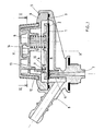
- the gas pressure regulator shown in FIGS. 1 and 2, comprises a membrane 1, the upper face of which is in contact with a plate 2 without being integral with it and the periphery of which is wedged between a body 3 and a cover 4 by crimping 5.
- the body 3 and the cover 4 are of general shape of revolution relative to the axis X, X ⁇ .
- the membrane 1 subdivides the space enclosed by the body 3 and by the cover 4 into two chambers A, B.
- the upper chamber A comprises the plate 2 and, at a distance from the axis X, X ⁇ , a spring 6, the one end rests on the top of the cover 4 and the other end pushes the plate 2.
- the other lower chamber B communicates with an inlet connection 7 and with an outlet connection 8, the plate 2 is articulated by an axis 9 of articulation on two bearings 10 coming from molding with the cover 4.
- the axis 9 represents a fulcrum provided between the spring 6 and the mouth of the inlet fitting 7 in the chamber B, around which the plate 2 can tilt by making the same tilt the membrane 1 which can be applied to the mouth of the inlet fitting 7 or away from it.
- a spring 11 of less stiffness than the spring 6 is threaded over the mouth of the inlet connector 7 and prevents the membrane 1 from being applied irreversibly to the mouth.
- Plate 2 leaves, at the point of the fulcrum, a tab 12 which extends parallel to the X, X ⁇ axis. The free end of the tab 12 is pushed back by an eccentric 13 molded with a handle 14 which can be turned manually by a quarter turn relative to the axis X, X ⁇ .
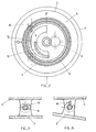
- FIG. 3 illustrates an embodiment of the articulation of the plate to the cover by an oblong bearing 15 allowing the axis 16 of articulation of the plate to be struggled laterally.
- a stop 17 molded with the cover 4 limits the tilting of the plate 2 in a clockwise direction.
- the stop 17 is on the other side of the spring 6 relative to the axis 9 of articulation of the plate 2.
- the stop 18 from the cover also limits the angular rotation of the plate 2.
- Figure 6 illustrates an alternative embodiment of the pressure reducing valve.
- the handle 14 of the valve attacks by a cam 19, a vertical branch 20 of a spring, a central turn of which is wound on the axis of rotation 9 allowing the plate 2 to tilt relative to the cover 4, the other branch 21 of the spring, substantially horizontal, applying a force to the plate 2.
- This force tends to tilt the plate in a trigonometric direction and therefore to apply the membrane 1 to the mouth of the inlet connector 7.
- the process for manufacturing the regulator consists in first creating the sub-assembly consisting of the plate 2, the cover 4 and the spring 6 then, without pre-setting in a particular station, to mount it on the body 3 and crimp.
- the subassembly constitutes a stable unit on which it is not necessary to apply forces to keep it stable.
Landscapes
- Engineering & Computer Science (AREA)
- Physics & Mathematics (AREA)
- Mechanical Engineering (AREA)
- General Engineering & Computer Science (AREA)
- Fluid Mechanics (AREA)
- General Physics & Mathematics (AREA)
- Automation & Control Theory (AREA)
- Control Of Fluid Pressure (AREA)
- Mechanically-Actuated Valves (AREA)
- Fluid-Driven Valves (AREA)
Applications Claiming Priority (2)
| Application Number | Priority Date | Filing Date | Title |
|---|---|---|---|
| FR8607294 | 1986-05-22 | ||
| FR8607294A FR2599160B1 (fr) | 1986-05-22 | 1986-05-22 | Detendeur de gaz et son procede de fabrication |
Publications (2)
| Publication Number | Publication Date |
|---|---|
| EP0246944A1 true EP0246944A1 (de) | 1987-11-25 |
| EP0246944B1 EP0246944B1 (de) | 1990-09-26 |
Family
ID=9335480
Family Applications (1)
| Application Number | Title | Priority Date | Filing Date |
|---|---|---|---|
| EP87401005A Expired - Lifetime EP0246944B1 (de) | 1986-05-22 | 1987-04-30 | Gasdruckverminderungsventil und Herstellungsverfahren |
Country Status (5)
| Country | Link |
|---|---|
| EP (1) | EP0246944B1 (de) |
| DE (1) | DE3765177D1 (de) |
| DK (1) | DK163386C (de) |
| ES (1) | ES2018031B3 (de) |
| FR (1) | FR2599160B1 (de) |
Cited By (1)
| Publication number | Priority date | Publication date | Assignee | Title |
|---|---|---|---|---|
| CN109373031A (zh) * | 2018-11-26 | 2019-02-22 | 乐山川天燃气输配设备有限公司 | 铰接结构直接作用式调压器 |
Families Citing this family (1)
| Publication number | Priority date | Publication date | Assignee | Title |
|---|---|---|---|---|
| DE19541051A1 (de) * | 1995-11-03 | 1997-05-07 | Gmt Gas Mes Und Regeltechnik G | Zweistufiger Gasdruckregler |
Citations (3)
| Publication number | Priority date | Publication date | Assignee | Title |
|---|---|---|---|---|
| US3900045A (en) * | 1973-09-27 | 1975-08-19 | Robertshaw Controls Co | Fulcrum pressure regulator |
| EP0150143A2 (de) * | 1984-01-19 | 1985-07-31 | Clesse-Mandet | Druckminderventil |
| FR2579337A1 (fr) * | 1985-03-20 | 1986-09-26 | Gurtner Sa | Appareil detendeur a membrane, en particulier pour gaz de petrole liquefie |
-
1986
- 1986-05-22 FR FR8607294A patent/FR2599160B1/fr not_active Expired - Fee Related
-
1987
- 1987-04-03 DK DK171787A patent/DK163386C/da active IP Right Grant
- 1987-04-30 DE DE8787401005T patent/DE3765177D1/de not_active Expired - Lifetime
- 1987-04-30 EP EP87401005A patent/EP0246944B1/de not_active Expired - Lifetime
- 1987-04-30 ES ES87401005T patent/ES2018031B3/es not_active Expired - Lifetime
Patent Citations (3)
| Publication number | Priority date | Publication date | Assignee | Title |
|---|---|---|---|---|
| US3900045A (en) * | 1973-09-27 | 1975-08-19 | Robertshaw Controls Co | Fulcrum pressure regulator |
| EP0150143A2 (de) * | 1984-01-19 | 1985-07-31 | Clesse-Mandet | Druckminderventil |
| FR2579337A1 (fr) * | 1985-03-20 | 1986-09-26 | Gurtner Sa | Appareil detendeur a membrane, en particulier pour gaz de petrole liquefie |
Cited By (2)
| Publication number | Priority date | Publication date | Assignee | Title |
|---|---|---|---|---|
| CN109373031A (zh) * | 2018-11-26 | 2019-02-22 | 乐山川天燃气输配设备有限公司 | 铰接结构直接作用式调压器 |
| CN109373031B (zh) * | 2018-11-26 | 2023-12-22 | 乐山川天燃气输配设备有限公司 | 铰接结构直接作用式调压器 |
Also Published As
| Publication number | Publication date |
|---|---|
| DK171787D0 (da) | 1987-04-03 |
| FR2599160A1 (fr) | 1987-11-27 |
| DK163386C (da) | 1992-07-13 |
| ES2018031B3 (es) | 1991-03-16 |
| DK171787A (da) | 1987-11-23 |
| DE3765177D1 (de) | 1990-10-31 |
| DK163386B (da) | 1992-02-24 |
| EP0246944B1 (de) | 1990-09-26 |
| FR2599160B1 (fr) | 1995-05-24 |
Similar Documents
| Publication | Publication Date | Title |
|---|---|---|
| EP2876504B1 (de) | Schraubenloser Spiralklötzchen-Träger für Uhr | |
| EP0547925B1 (de) | Vorrichtung zum Abgeben eines Produktes, insbesondere eines aufschäumenden Produktes | |
| FR2591360A1 (fr) | Mecanisme a levier de manoeuvre reglable, notamment pour motocyclette | |
| EP0604267A1 (de) | Ringklemme für Mundstück eines Blasinstruments | |
| EP1576426A2 (de) | Feinregulierungsvorrichtung für eine unruh-spiralfeder | |
| WO1998015377A1 (fr) | Monture de scie a metaux du type archet monobloc avec dispositif de mise en tension de la lame | |
| EP0272746A2 (de) | Ausrichtbare Haltevorrichtung, speziell für optische Geräte und ähnliches | |
| EP0246944B1 (de) | Gasdruckverminderungsventil und Herstellungsverfahren | |
| EP0887092B1 (de) | Sicherheitsskibindung | |
| EP2110115B1 (de) | Fläschchen mit Befestigung des Saugers durch einen Ring aus mehreren beweglichen Elementen, sowie entsprechender Ring und Sauger | |
| FR2692559A1 (fr) | Dispositif de sécurité pour récipient de conditionnement muni d'un organe de distribution comportant une tige de manÓoeuvre. | |
| EP3835888A1 (de) | Werkzeug und verfahren zum auswechseln eines armbanduhrenglases | |
| EP0279708B1 (de) | Reduzierventil für Gase mit schwenkbarer Membran | |
| EP1641567A1 (de) | Pulverdiffusordüse für eine elektrostatische entstaubungsvorrichtung mit ausgerichtetem pulverstrahl | |
| EP0310508A2 (de) | Gestell mit Tisch für eine Handtrenn- oder Handschleifmaschine | |
| FR2624780A1 (fr) | Dispositif de mise en tension de lame d'une scie a main et de verrouillage en position et la monture de scie mettant en oeuvre le dispositif | |
| EP0115779B1 (de) | Bedienungshebel für Fahrradgangschaltung | |
| FR2509885A1 (fr) | Bloc de commande a pedale | |
| EP0587465A1 (de) | Aussentürgriff für Autotüre | |
| EP0266253B1 (de) | Gasdruckreduzierventil mit kippender Membrane | |
| EP3803001B1 (de) | Vorhängeschlossvorrichtung und verfahren zum zusammenbau einer solchen vorrichtung | |
| EP4123391B1 (de) | Uhrenkomponente zur befestigung auf einer welle und verfahren | |
| EP2567789B1 (de) | Montagegerät eines Befestigungselements | |
| EP3333059B1 (de) | Automatisches fahrradpedal | |
| FR1252092A (fr) | Perfectionnements aux dispositifs d'étau pour tronçonneuses et machines-outils analogues |
Legal Events
| Date | Code | Title | Description |
|---|---|---|---|
| PUAI | Public reference made under article 153(3) epc to a published international application that has entered the european phase |
Free format text: ORIGINAL CODE: 0009012 |
|
| AK | Designated contracting states |
Kind code of ref document: A1 Designated state(s): DE ES GB IT |
|
| 17P | Request for examination filed |
Effective date: 19880224 |
|
| 17Q | First examination report despatched |
Effective date: 19900215 |
|
| GRAA | (expected) grant |
Free format text: ORIGINAL CODE: 0009210 |
|
| AK | Designated contracting states |
Kind code of ref document: B1 Designated state(s): DE ES GB IT |
|
| REF | Corresponds to: |
Ref document number: 3765177 Country of ref document: DE Date of ref document: 19901031 |
|
| GBT | Gb: translation of ep patent filed (gb section 77(6)(a)/1977) | ||
| ITF | It: translation for a ep patent filed | ||
| ITTA | It: last paid annual fee | ||
| PLBE | No opposition filed within time limit |
Free format text: ORIGINAL CODE: 0009261 |
|
| STAA | Information on the status of an ep patent application or granted ep patent |
Free format text: STATUS: NO OPPOSITION FILED WITHIN TIME LIMIT |
|
| 26N | No opposition filed | ||
| PGFP | Annual fee paid to national office [announced via postgrant information from national office to epo] |
Ref country code: GB Payment date: 19980225 Year of fee payment: 12 |
|
| PGFP | Annual fee paid to national office [announced via postgrant information from national office to epo] |
Ref country code: DE Payment date: 19980320 Year of fee payment: 12 |
|
| PGFP | Annual fee paid to national office [announced via postgrant information from national office to epo] |
Ref country code: ES Payment date: 19980401 Year of fee payment: 12 |
|
| PG25 | Lapsed in a contracting state [announced via postgrant information from national office to epo] |
Ref country code: GB Free format text: LAPSE BECAUSE OF NON-PAYMENT OF DUE FEES Effective date: 19990430 |
|
| PG25 | Lapsed in a contracting state [announced via postgrant information from national office to epo] |
Ref country code: ES Free format text: LAPSE BECAUSE OF EXPIRATION OF PROTECTION Effective date: 19990503 |
|
| GBPC | Gb: european patent ceased through non-payment of renewal fee |
Effective date: 19990430 |
|
| PG25 | Lapsed in a contracting state [announced via postgrant information from national office to epo] |
Ref country code: DE Free format text: LAPSE BECAUSE OF NON-PAYMENT OF DUE FEES Effective date: 20000201 |
|
| REG | Reference to a national code |
Ref country code: ES Ref legal event code: FD2A Effective date: 20010601 |
|
| PG25 | Lapsed in a contracting state [announced via postgrant information from national office to epo] |
Ref country code: IT Free format text: LAPSE BECAUSE OF NON-PAYMENT OF DUE FEES;WARNING: LAPSES OF ITALIAN PATENTS WITH EFFECTIVE DATE BEFORE 2007 MAY HAVE OCCURRED AT ANY TIME BEFORE 2007. THE CORRECT EFFECTIVE DATE MAY BE DIFFERENT FROM THE ONE RECORDED. Effective date: 20050430 |