EP0246818A2 - Nachfüllanordnung für Hydraulikflüssigkeit - Google Patents
Nachfüllanordnung für Hydraulikflüssigkeit Download PDFInfo
- Publication number
- EP0246818A2 EP0246818A2 EP87304313A EP87304313A EP0246818A2 EP 0246818 A2 EP0246818 A2 EP 0246818A2 EP 87304313 A EP87304313 A EP 87304313A EP 87304313 A EP87304313 A EP 87304313A EP 0246818 A2 EP0246818 A2 EP 0246818A2
- Authority
- EP
- European Patent Office
- Prior art keywords
- hydraulic fluid
- reservoir
- hydraulic
- connection
- old
- Prior art date
- Legal status (The legal status is an assumption and is not a legal conclusion. Google has not performed a legal analysis and makes no representation as to the accuracy of the status listed.)
- Granted
Links
- 239000012530 fluid Substances 0.000 title claims abstract description 115
- 230000004048 modification Effects 0.000 claims description 2
- 238000012986 modification Methods 0.000 claims description 2
- 230000000717 retained effect Effects 0.000 abstract 1
- 210000002445 nipple Anatomy 0.000 description 14
- 230000037452 priming Effects 0.000 description 8
- 230000000284 resting effect Effects 0.000 description 2
- 238000007789 sealing Methods 0.000 description 2
- 229910000831 Steel Inorganic materials 0.000 description 1
- 238000010276 construction Methods 0.000 description 1
- 238000009434 installation Methods 0.000 description 1
- 239000000463 material Substances 0.000 description 1
- 229920000515 polycarbonate Polymers 0.000 description 1
- 239000004417 polycarbonate Substances 0.000 description 1
- 239000010959 steel Substances 0.000 description 1
Images


Classifications
-
- F—MECHANICAL ENGINEERING; LIGHTING; HEATING; WEAPONS; BLASTING
- F15—FLUID-PRESSURE ACTUATORS; HYDRAULICS OR PNEUMATICS IN GENERAL
- F15B—SYSTEMS ACTING BY MEANS OF FLUIDS IN GENERAL; FLUID-PRESSURE ACTUATORS, e.g. SERVOMOTORS; DETAILS OF FLUID-PRESSURE SYSTEMS, NOT OTHERWISE PROVIDED FOR
- F15B7/00—Systems in which the movement produced is definitely related to the output of a volumetric pump; Telemotors
- F15B7/06—Details
- F15B7/10—Compensation of the liquid content in a system
-
- B—PERFORMING OPERATIONS; TRANSPORTING
- B21—MECHANICAL METAL-WORKING WITHOUT ESSENTIALLY REMOVING MATERIAL; PUNCHING METAL
- B21J—FORGING; HAMMERING; PRESSING METAL; RIVETING; FORGE FURNACES
- B21J15/00—Riveting
- B21J15/10—Riveting machines
- B21J15/16—Drives for riveting machines; Transmission means therefor
- B21J15/22—Drives for riveting machines; Transmission means therefor operated by both hydraulic or liquid pressure and gas pressure
-
- Y—GENERAL TAGGING OF NEW TECHNOLOGICAL DEVELOPMENTS; GENERAL TAGGING OF CROSS-SECTIONAL TECHNOLOGIES SPANNING OVER SEVERAL SECTIONS OF THE IPC; TECHNICAL SUBJECTS COVERED BY FORMER USPC CROSS-REFERENCE ART COLLECTIONS [XRACs] AND DIGESTS
- Y10—TECHNICAL SUBJECTS COVERED BY FORMER USPC
- Y10T—TECHNICAL SUBJECTS COVERED BY FORMER US CLASSIFICATION
- Y10T29/00—Metal working
- Y10T29/53—Means to assemble or disassemble
- Y10T29/53709—Overedge assembling means
- Y10T29/53717—Annular work
- Y10T29/53726—Annular work with second workpiece inside annular work one workpiece moved to shape the other
- Y10T29/5373—Annular work with second workpiece inside annular work one workpiece moved to shape the other comprising driver for snap-off-mandrel fastener; e.g., Pop [TM] riveter
- Y10T29/53739—Pneumatic- or fluid-actuated tool
- Y10T29/53743—Liquid
Definitions
- the invention relates to a hydraulic fluid replenishment device. More particularly, it relates to such a device for use with a hydraulic system embodied in a portable tool, under works or factory-floor conditions.
- a replenishment device is meant a device which will allow the addition of new hydraulic fluid to a system to replace fluid lost e.g. by leakage. Such loss leaves air in the system, and it is necessary to remove this air. Preferably this air is removed by pressurizing the hydraulic-system to force the air but. In practice, some old hydraulic fluid, which may be mixed with air bubbles, may also be forced out of the system, in order to ensure that all the air has been removed.
- the present invention provides, in one of its aspects, a hydraulic fluid replenishment device for replenishing hydraulic fluid in a hydraulic system, which device comprises:
- the invention provides, in another of its aspects, a hydraulic fluid replenishment device for replenishing hydraulic fluid in a hydraulic system, which comprises:
- the replenishment device of this example is generally cylindrical in form and comprises three separate parts, a body member 11, a tray member 12 and a cap member 13.
- a single hydraulic connection between the device and the hydraulic system with which it is to be used- is provided by a nipple 14 which passes through a boss 15 with centre of the bottom wall or floor of the body 11.
- the nipple is secured and sealed in the boss and its projecting lower end is externally threaded at 16 so that it can make a screw connection with the external system. Hydraulic fluid can pass in either direction through the bore 17 in the nipple.
- the uppermost end part of the body 11 is externally threaded at 18, immediately below which there is an outwardly projecting annular flange 19.
- the tray member 12 is of an external diameter slightly smaller than the internal diameter of the body 11, so as to be an easy fit therein.
- the upper end of the tray 12 has an outwardly projecting annular flange 21, which contacts the upper end of the body wall to support the tray within the. uppermost part of the body, as illustrated in Figures 2, 3 and 4.
- the tray 11 includes a conduit provided by the bore 22 of a pipe 23 which is formed integrally with the tray 11.
- the pipe 23 extends axially of the tray 11, with the top end 24 of the pipe level with the top of the tray 11.
- the pipe also extends downwards below the bottom of the tray 12 by a sufficient distance that, when the tray 12 and the body 11 are assembled together as illustrated in Figure 2 with the flange 21 of the tray resting on the top edge of the body, the bottom end 25 of the pipe is-opposite the inner end of the nipple bore 17 but spaced from it axially.
- a gap or cut-out 37 is provided at a number of positions around the flange 21 . These gaps allow air to pass between the interior of the tray 12 and the interior of the body 11, when tray and body are assembled together.
- the cap 13 is internally threaded at 26 to engage with the external threading 18 on the body 11.
- the depth of the cap 13 is such that when the tray 12 has its flange 21 resting on top of the body wall and the cap is screwed onto the body, the bottom of the cap 13 contacts the body flange 19 to seal against it while there is a slight clearance between the top of the tray flange 21 and the underside 27 of the top wall-of the cap.
- the centre part of the top wall of the cap is extended upwards to form a dome 30 with a downwardly curving edge 40.
- the body 11, tray 12 and cap 13 are made of moulded synthetic resin-material, e.g. polycarbonate, and are advantageously transparent.
- the connection nipple 14 is made of steel.
- the three parts of the device are assembled together as described above and as illustrated in Figure 2.
- the tray 12 then provides a first reservoir 28 for holding old hydraulic fluid removed from the external hydraulic system, while the lowermost part of the body 11 provides a second reservoir 29 for holding new hydraulic fluid to be added to the system.
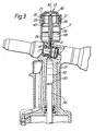
- FIGs 2, 3 and 4 illustrate the use of-this replenishment device with a portable hydraulic system in the form of a hand-held hydraulically operated blind-riveting gun 31.
- the details of construction and operation of the gun are not important to the present invention, except that the gun includes a hydraulic pressure chamber 32 containing hydraulic fluid 33, and that the hydraulic fluid must often be replenished while the gun is being used in a workshop or on a factory floor, to fill the airspace 34 (Fig.2) left due to leakage of the hydraulic fluid.
- the hydraulic fluid in the gun can be pressurised by actuating the gun to force a hydraulic piston rod 35 into the chamber 32 to displace the fluid 33.
- the hydraulic system of the gun includes a priming hole 36 through which hydraulic fluid can be added to the system.
- the priming hole is normally sealed by a threaded screw plug, and the screw thread 16 on the connection nipple 14 is of course selected to match the screw thread in the gun priming hole.
- the priming hole is positioned to be at the highest part of the gun hydraulic system when the gun is held vertically, and it is connected to the hydraulic pressure chamber 32 through an annular space 38 around a reduced diameter portion of a slave piston in a slave cylinder.
- the proceedure for using the device to replenish the hydraulic fluid in the gun is as follows.
- the gun 31 is supported firmly in with its body in a vertical position as illustrated in Figure 2, with the piston rod 35 in the retracted position.
- the sealing screw plug is removed from the priming hole 36.
- the replenishment device is dismantled, and the body portion 11 alone is offered up to the gun, and connection nipple 14 is screwed into the priming hole 36 so that they seal together.
- the body portion is also thereby supported in a vertical position on the gun.
- a suitable quantity of new hydraulic fluid is then poured into the body portion 11 of the device.
- the fluid level comes about one third of the way up the body portion.
- a mark or level indicator may be provided on the side of the body portion 11 to indicate the required level of fluid.
- New hydraulic fluid does not run through the bore 17 of the connection nipple 14, due to viscosity and surface tension of the fluid, and the small diameter of the bore . 17.
- the remaining parts of the replenishment device are then assembled, by placing the tray member 12 in the top of the body member 11, and screwing on the cap member 13, as previously described. The position is then as illustrated in Figure 2. It will be seen that the new hydraulic fluid 39 in the second reservoir 29 provided by the body member 11 covers the lowermost part of the cap member pipe 23. The bottom end 25 of the pipe is opposite and immediately above the upper, inner end of the bore 17 through the connection nipple; but spaced away axially from it.
- the second reservoir 29 communicates with the connection nipple bore 17 via the space 41 between the bottom 25 of the pipe 23 and the top of the connection nipple. This space therefore provides an exit port from the second reservoir 29. Similarly the bottom end 25 of pipe 23 provides an entry port to the first reservoir 28.
- the hydraulic fluid in the gun is now pressurised by actuating the gun mechanism to drive the piston rod 35 upwardly into the hydraulic chamber 32. This displaces the old hydraulic fluid 33 and the air 34 above it.
- First the air, and then the old hydraulic fluid, are expelled from the gun through the connection nipple bore 17 at a considerable linear speed. They emerge from the top of the bore 17 as a high speed stream, and have sufficient momentum to pass vertically upwards into the bottom end 25 of pipe 23, and up the whole length of pipe 23.
- This high speed upward passage of air and old hydraulic fluid will carry with it the part of the new hydraulic fluid within the lower end of pipe 23, and also may well suck in and entrain with it some new hydraulic fluid from the second reservoir, through the exit port 41.
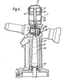
- the hydraulic fluid in the gun is now depressurised (i.e. has negative hydraulic pressure applied to it) by actuating the gun mechanism to retract the piston rod 35 from the hydraulic chamber 32.
- This draws new hydraulic fluid 39 from the second reservoir 29 through the exit port 41 and down through the bore 17 of the connection nipple, into the hydraulic system of the gun, to fill it up with hydraulic fluid. This is the position illustrated in Figure 4.
- the piston rod 35 may be given a second stroke, to expel the remainder of the air and replace it by new hydraulic fluid.
- the volume of new fluid initially poured into the second reservoir 29 is arranged to be sufficient to accommodate this. In order to ensure that all air has been removed from the hydraulic system, it is necessary .to check that old oil without-air bubbles is entering the first reservoir.
- the replenishment device When the gun hydraulic system is thus full of hydraulic fluid, the replenishment device is unscrewed from the priming hole 36 and replaced by the sealing screw plug. The replenishment device is dismantled, the old fluid is disposed of, and the device is cleaned ready for re-use.
- this device enables the replenishment of hydraulic fluid, in a system, in a very simple operation.
- the device can be connected to the hydraulic system through a single connection to an existing priming hole, and contains no non-return valves or on-off valves.
- Figure 5 shows a slightly modified version, in which the tray pipe 23 does not project so far downwards into the second reservoir 29.
- the lower end 25 of the pipe is no lower than the level of the new hydraulic fluid 39 in the reservoir 29, and this level is indicated by a mark or level indicator 20 moulded into the outside of the wall of the body member 11, which is transparent.
- the space above the connection nipple 14 and below the lower end 25 of the pipe 23 is thus much greater than in the example illustrated in Figure 2, and it is believed that this overcomes a problem sometimes found in use of the example of Figure 2, in which, when the external hydraulic system is depressurised, it sometimes happens that a bubble of air is sucked down the tube 23 into the connection bore 17, which is unacceptable. With the reduced downwards extent of the tube 23, this problem does not occur.
- the old hydraulic fluid and/or air still enters the bottom end 25 of the pipe 23 without contaminating the new hydraulic fluid 39.
- the tray pipe 23 could extend downwardly by any suitable distance, which provides the correct functioning of the device, whether the pipe enters the new hydraulic fluid, just touches it, or does not reach the level of the new hydraulic fluid.
- the pipe could extend downwards only as far as the bottom of the tray member 12, so that it does not actually project into the second reservoir.
Landscapes
- Engineering & Computer Science (AREA)
- Mechanical Engineering (AREA)
- Physics & Mathematics (AREA)
- Fluid Mechanics (AREA)
- General Engineering & Computer Science (AREA)
- Valves And Accessory Devices For Braking Systems (AREA)
- Loading And Unloading Of Fuel Tanks Or Ships (AREA)
Priority Applications (1)
| Application Number | Priority Date | Filing Date | Title |
|---|---|---|---|
| AT87304313T ATE75298T1 (de) | 1986-05-23 | 1987-05-15 | Nachfuellanordnung fuer hydraulikfluessigkeit. |
Applications Claiming Priority (4)
| Application Number | Priority Date | Filing Date | Title |
|---|---|---|---|
| GB868612689A GB8612689D0 (en) | 1986-05-23 | 1986-05-23 | Hydraulic fluid replenishment device |
| GB8612689 | 1986-05-23 | ||
| GB8615100A GB2192235B (en) | 1986-05-23 | 1986-06-20 | Hydraulic fluid replenishment device |
| GB8615100 | 1986-06-20 |
Publications (3)
| Publication Number | Publication Date |
|---|---|
| EP0246818A2 true EP0246818A2 (de) | 1987-11-25 |
| EP0246818A3 EP0246818A3 (en) | 1988-11-30 |
| EP0246818B1 EP0246818B1 (de) | 1992-04-22 |
Family
ID=26290811
Family Applications (1)
| Application Number | Title | Priority Date | Filing Date |
|---|---|---|---|
| EP87304313A Expired - Lifetime EP0246818B1 (de) | 1986-05-23 | 1987-05-15 | Nachfüllanordnung für Hydraulikflüssigkeit |
Country Status (8)
| Country | Link |
|---|---|
| US (1) | US4804023A (de) |
| EP (1) | EP0246818B1 (de) |
| JP (1) | JPH0829799B2 (de) |
| AU (1) | AU596771B2 (de) |
| BR (1) | BR8702544A (de) |
| CA (1) | CA1276605C (de) |
| DE (1) | DE3778421D1 (de) |
| ES (1) | ES2005591A6 (de) |
Cited By (2)
| Publication number | Priority date | Publication date | Assignee | Title |
|---|---|---|---|---|
| FR2637651A1 (fr) * | 1988-10-11 | 1990-04-13 | Sundstrand Corp | Dispositif a utiliser avec un moteur |
| EP0353288A4 (en) * | 1987-12-24 | 1990-09-05 | Sundstrand Corporation | Process and apparatus for filling a constant speed drive |
Families Citing this family (18)
| Publication number | Priority date | Publication date | Assignee | Title |
|---|---|---|---|---|
| GB2301547A (en) * | 1995-06-02 | 1996-12-11 | Avdel Systems Ltd | Fastener installation tool |
| US5653316A (en) * | 1995-06-29 | 1997-08-05 | Kane; Michael J. | Hydraulic system bleeding |
| US6233933B1 (en) * | 1996-10-29 | 2001-05-22 | Phoenix Systems, L.L.C. | Arrangement and method for removal of air from a hydraulic system |
| US5931347A (en) * | 1997-05-23 | 1999-08-03 | Haubrich; Mark A. | Dispenser unit for viscous substances |
| US6162133A (en) * | 1997-11-03 | 2000-12-19 | Peterson; Lane | Golf club head |
| US7008433B2 (en) | 2001-02-15 | 2006-03-07 | Depuy Acromed, Inc. | Vertebroplasty injection device |
| DE60335037D1 (de) | 2003-03-14 | 2010-12-30 | Depuy Spine Inc | Hydraulische vorrichtung zur knochenzementeinspritzung bei perkutaner vertebroplastie |
| US8066713B2 (en) * | 2003-03-31 | 2011-11-29 | Depuy Spine, Inc. | Remotely-activated vertebroplasty injection device |
| US20070032567A1 (en) * | 2003-06-17 | 2007-02-08 | Disc-O-Tech Medical | Bone Cement And Methods Of Use Thereof |
| US8415407B2 (en) | 2004-03-21 | 2013-04-09 | Depuy Spine, Inc. | Methods, materials, and apparatus for treating bone and other tissue |
| WO2005030034A2 (en) | 2003-09-26 | 2005-04-07 | Depuy Spine, Inc. | Device for delivering viscous material |
| CA2575699C (en) | 2004-07-30 | 2014-07-08 | Disc-O-Tech Medical Technologies Ltd. | Methods, materials and apparatus for treating bone and other tissue |
| US9381024B2 (en) * | 2005-07-31 | 2016-07-05 | DePuy Synthes Products, Inc. | Marked tools |
| US9918767B2 (en) | 2005-08-01 | 2018-03-20 | DePuy Synthes Products, Inc. | Temperature control system |
| US8360629B2 (en) * | 2005-11-22 | 2013-01-29 | Depuy Spine, Inc. | Mixing apparatus having central and planetary mixing elements |
| WO2008032322A2 (en) | 2006-09-14 | 2008-03-20 | Depuy Spine, Inc. | Bone cement and methods of use thereof |
| EP2091818B1 (de) | 2006-10-19 | 2016-06-08 | DePuy Spine, Inc. | Fluidzufuhrsystem und darauf bezogenes verfahren |
| US7575029B2 (en) * | 2007-05-29 | 2009-08-18 | Production Control Units, Inc. | Tool assembly for evacuating, vacuum testing and charging a fluid system through a bleeder valve |
Family Cites Families (13)
| Publication number | Priority date | Publication date | Assignee | Title |
|---|---|---|---|---|
| US1617020A (en) * | 1925-06-15 | 1927-02-08 | George S Merwin | Liquid saving, replenishing, and air-bleeding mechanism for hydraulic brakes |
| GB573362A (en) * | 1944-05-11 | 1945-11-16 | Keelavite Co Ltd | Improvements in or relating to hydraulic systems |
| FR940929A (fr) * | 1944-05-15 | 1948-12-28 | Vickers Armstrongs Ltd | Perfectionnement dans les installations d'alimentation en liquide pour circulation de liquides sous pression |
| US2645314A (en) * | 1951-10-09 | 1953-07-14 | Frank P Lackinger | Apparatus for bleeding air and replacing liquid in hydraulic brake systems |
| GB868125A (en) * | 1956-08-16 | 1961-05-17 | Sueddeutsche Kuehler Behr | Apparatus for removing air entrained in the driving medium of hydraulic motors |
| GB945469A (en) * | 1959-01-06 | 1964-01-02 | Girling Ltd | Replenishing hydraulic braking and other systems |
| US3154087A (en) * | 1961-12-26 | 1964-10-27 | Quadrant Engineering Corp | Means and method for purging a hydraulic system |
| DE1450844A1 (de) * | 1964-02-18 | 1969-07-17 | Schierholz Kg Louis | Vorrichtung zum Antrieb fuer hin- und hergehende oder monotone,schrittweise Bewegung,insbesondere fuer den Schwenkvorschub von Entnahmefraesen in Gruenfuttersilos mit Untenentnahme |
| US4009739A (en) * | 1975-09-02 | 1977-03-01 | Weatherford Danny J | Gasoline and vapor return hose system for delivery truck |
| US4144913A (en) * | 1977-01-26 | 1979-03-20 | Nordson Corporation | Hot melt adhesive dispensing system of the hand held gun type |
| SE432164B (sv) * | 1979-12-20 | 1984-03-19 | Tudor Ab | Vetskepafyllningssystem for ackumulatorceller |
| DE3040478C2 (de) * | 1980-10-28 | 1986-07-10 | Uraca Pumpenfabrik GmbH & Co KG, 7432 Bad Urach | Pumpe od.dgl. hydraulische Arbeitsmaschine |
| FR2525701B1 (fr) * | 1982-04-21 | 1987-01-23 | Dba | Dispositif de purge pour ensemble a cylindre et piston et moteur de frein equipe d'un tel dispositif |
-
1987
- 1987-05-15 EP EP87304313A patent/EP0246818B1/de not_active Expired - Lifetime
- 1987-05-15 DE DE8787304313T patent/DE3778421D1/de not_active Expired - Fee Related
- 1987-05-19 US US07/051,328 patent/US4804023A/en not_active Expired - Fee Related
- 1987-05-19 BR BR8702544A patent/BR8702544A/pt not_active IP Right Cessation
- 1987-05-22 AU AU73309/87A patent/AU596771B2/en not_active Ceased
- 1987-05-22 CA CA000537752A patent/CA1276605C/en not_active Expired - Fee Related
- 1987-05-22 ES ES8701510A patent/ES2005591A6/es not_active Expired
- 1987-05-22 JP JP62124113A patent/JPH0829799B2/ja not_active Expired - Lifetime
Cited By (2)
| Publication number | Priority date | Publication date | Assignee | Title |
|---|---|---|---|---|
| EP0353288A4 (en) * | 1987-12-24 | 1990-09-05 | Sundstrand Corporation | Process and apparatus for filling a constant speed drive |
| FR2637651A1 (fr) * | 1988-10-11 | 1990-04-13 | Sundstrand Corp | Dispositif a utiliser avec un moteur |
Also Published As
| Publication number | Publication date |
|---|---|
| JPS62287895A (ja) | 1987-12-14 |
| EP0246818A3 (en) | 1988-11-30 |
| JPH0829799B2 (ja) | 1996-03-27 |
| BR8702544A (pt) | 1988-02-23 |
| DE3778421D1 (de) | 1992-05-27 |
| CA1276605C (en) | 1990-11-20 |
| EP0246818B1 (de) | 1992-04-22 |
| AU596771B2 (en) | 1990-05-10 |
| US4804023A (en) | 1989-02-14 |
| ES2005591A6 (es) | 1989-03-16 |
| AU7330987A (en) | 1987-11-26 |
Similar Documents
| Publication | Publication Date | Title |
|---|---|---|
| US4804023A (en) | Hydraulic fluid replenishment device | |
| US4785629A (en) | Syringe-dispensed brake fluid for filling and purging master cylinder circuit from slave | |
| EP0645526A1 (de) | Oelwechselanlage fuer motoroel und/oder fuer oelfilter von brennkraftmaschine | |
| US4197097A (en) | Apparatus for venting gas from afluid system | |
| US20100065375A1 (en) | Reduced gulp fluid reservoir | |
| US4618273A (en) | Step bearing for a spinning rotor shaft | |
| US5127287A (en) | Hydraulic breathing apparatus for a hydraulic device | |
| GB2192235A (en) | Replenishing hydraulic fluid | |
| EP1790903A1 (de) | Schmiervorrichtung | |
| US4759476A (en) | Venting apparatus for liquid-filled systems | |
| US4895222A (en) | Constant level oiler | |
| EP1945996B1 (de) | Bord-schmiersystem für kolben-farbpumpe | |
| US4778312A (en) | Blind hole drilling coolant remover and tapping fluid injector and method | |
| JPS61192995A (ja) | 給油器 | |
| SE521029C2 (sv) | Förträngningspump | |
| SE8306023D0 (sv) | Restlensanordning for tankutrymme i fartyg | |
| US5289898A (en) | Method and apparatus for maintaining lubricant in an internal combustion engine | |
| WO1983000207A1 (en) | Universal fluid level maintainer | |
| HK61388A (en) | Hydraulic buffer for elevators | |
| SU1481383A1 (ru) | Автоматическое устройство дл подачи раствора ПАВ в затрубное пространство газовой скважины | |
| KR20210107382A (ko) | 오링 고급 장치 및 오링 공급 시스템 | |
| US3220425A (en) | Lubricating device | |
| JP2002310389A (ja) | ミキシングバルブ | |
| EP4632160A1 (de) | Einsatz für einen duschablauf und duschablauf | |
| KR200156100Y1 (ko) | 오일 레벨 게이지 |
Legal Events
| Date | Code | Title | Description |
|---|---|---|---|
| PUAI | Public reference made under article 153(3) epc to a published international application that has entered the european phase |
Free format text: ORIGINAL CODE: 0009012 |
|
| AK | Designated contracting states |
Kind code of ref document: A2 Designated state(s): AT BE CH DE FR GB IT LI LU NL SE |
|
| PUAL | Search report despatched |
Free format text: ORIGINAL CODE: 0009013 |
|
| RAP1 | Party data changed (applicant data changed or rights of an application transferred) |
Owner name: AVDEL SYSTEMS LIMITED |
|
| AK | Designated contracting states |
Kind code of ref document: A3 Designated state(s): AT BE CH DE FR GB IT LI LU NL SE |
|
| 17P | Request for examination filed |
Effective date: 19890421 |
|
| 17Q | First examination report despatched |
Effective date: 19900827 |
|
| GRAA | (expected) grant |
Free format text: ORIGINAL CODE: 0009210 |
|
| AK | Designated contracting states |
Kind code of ref document: B1 Designated state(s): AT BE CH DE FR GB IT LI LU NL SE |
|
| PG25 | Lapsed in a contracting state [announced via postgrant information from national office to epo] |
Ref country code: NL Effective date: 19920422 Ref country code: LI Effective date: 19920422 Ref country code: CH Effective date: 19920422 Ref country code: BE Effective date: 19920422 |
|
| REF | Corresponds to: |
Ref document number: 75298 Country of ref document: AT Date of ref document: 19920515 Kind code of ref document: T |
|
| REF | Corresponds to: |
Ref document number: 3778421 Country of ref document: DE Date of ref document: 19920527 |
|
| PG25 | Lapsed in a contracting state [announced via postgrant information from national office to epo] |
Ref country code: LU Free format text: LAPSE BECAUSE OF NON-PAYMENT OF DUE FEES Effective date: 19920531 |
|
| ITF | It: translation for a ep patent filed | ||
| REG | Reference to a national code |
Ref country code: CH Ref legal event code: PL |
|
| ET | Fr: translation filed | ||
| NLV1 | Nl: lapsed or annulled due to failure to fulfill the requirements of art. 29p and 29m of the patents act | ||
| PLBE | No opposition filed within time limit |
Free format text: ORIGINAL CODE: 0009261 |
|
| STAA | Information on the status of an ep patent application or granted ep patent |
Free format text: STATUS: NO OPPOSITION FILED WITHIN TIME LIMIT |
|
| 26N | No opposition filed | ||
| ITTA | It: last paid annual fee | ||
| EAL | Se: european patent in force in sweden |
Ref document number: 87304313.7 |
|
| PGFP | Annual fee paid to national office [announced via postgrant information from national office to epo] |
Ref country code: SE Payment date: 19970218 Year of fee payment: 11 |
|
| PGFP | Annual fee paid to national office [announced via postgrant information from national office to epo] |
Ref country code: AT Payment date: 19970526 Year of fee payment: 11 |
|
| PG25 | Lapsed in a contracting state [announced via postgrant information from national office to epo] |
Ref country code: AT Free format text: LAPSE BECAUSE OF NON-PAYMENT OF DUE FEES Effective date: 19980515 |
|
| PG25 | Lapsed in a contracting state [announced via postgrant information from national office to epo] |
Ref country code: SE Free format text: LAPSE BECAUSE OF NON-PAYMENT OF DUE FEES Effective date: 19980516 |
|
| EUG | Se: european patent has lapsed |
Ref document number: 87304313.7 |
|
| PGFP | Annual fee paid to national office [announced via postgrant information from national office to epo] |
Ref country code: FR Payment date: 19990324 Year of fee payment: 13 Ref country code: DE Payment date: 19990324 Year of fee payment: 13 |
|
| PGFP | Annual fee paid to national office [announced via postgrant information from national office to epo] |
Ref country code: GB Payment date: 19990331 Year of fee payment: 13 |
|
| PG25 | Lapsed in a contracting state [announced via postgrant information from national office to epo] |
Ref country code: GB Free format text: LAPSE BECAUSE OF NON-PAYMENT OF DUE FEES Effective date: 20000515 |
|
| GBPC | Gb: european patent ceased through non-payment of renewal fee |
Effective date: 20000515 |
|
| PG25 | Lapsed in a contracting state [announced via postgrant information from national office to epo] |
Ref country code: FR Free format text: LAPSE BECAUSE OF NON-PAYMENT OF DUE FEES Effective date: 20010131 |
|
| PG25 | Lapsed in a contracting state [announced via postgrant information from national office to epo] |
Ref country code: DE Free format text: LAPSE BECAUSE OF NON-PAYMENT OF DUE FEES Effective date: 20010301 |
|
| REG | Reference to a national code |
Ref country code: FR Ref legal event code: ST |
|
| PG25 | Lapsed in a contracting state [announced via postgrant information from national office to epo] |
Ref country code: IT Free format text: LAPSE BECAUSE OF NON-PAYMENT OF DUE FEES;WARNING: LAPSES OF ITALIAN PATENTS WITH EFFECTIVE DATE BEFORE 2007 MAY HAVE OCCURRED AT ANY TIME BEFORE 2007. THE CORRECT EFFECTIVE DATE MAY BE DIFFERENT FROM THE ONE RECORDED. Effective date: 20050515 |