EP0246760A2 - Dispositif d'essai à volume variable et méthode - Google Patents
Dispositif d'essai à volume variable et méthode Download PDFInfo
- Publication number
- EP0246760A2 EP0246760A2 EP87303647A EP87303647A EP0246760A2 EP 0246760 A2 EP0246760 A2 EP 0246760A2 EP 87303647 A EP87303647 A EP 87303647A EP 87303647 A EP87303647 A EP 87303647A EP 0246760 A2 EP0246760 A2 EP 0246760A2
- Authority
- EP
- European Patent Office
- Prior art keywords
- membrane
- chamber
- reagent
- liquid sample
- volume
- Prior art date
- Legal status (The legal status is an assumption and is not a legal conclusion. Google has not performed a legal analysis and makes no representation as to the accuracy of the status listed.)
- Granted
Links
Images


Classifications
-
- B—PERFORMING OPERATIONS; TRANSPORTING
- B01—PHYSICAL OR CHEMICAL PROCESSES OR APPARATUS IN GENERAL
- B01L—CHEMICAL OR PHYSICAL LABORATORY APPARATUS FOR GENERAL USE
- B01L3/00—Containers or dishes for laboratory use, e.g. laboratory glassware; Droppers
- B01L3/50—Containers for the purpose of retaining a material to be analysed, e.g. test tubes
- B01L3/502—Containers for the purpose of retaining a material to be analysed, e.g. test tubes with fluid transport, e.g. in multi-compartment structures
-
- G—PHYSICS
- G01—MEASURING; TESTING
- G01N—INVESTIGATING OR ANALYSING MATERIALS BY DETERMINING THEIR CHEMICAL OR PHYSICAL PROPERTIES
- G01N33/00—Investigating or analysing materials by specific methods not covered by groups G01N1/00 - G01N31/00
- G01N33/48—Biological material, e.g. blood, urine; Haemocytometers
- G01N33/50—Chemical analysis of biological material, e.g. blood, urine; Testing involving biospecific ligand binding methods; Immunological testing
- G01N33/53—Immunoassay; Biospecific binding assay; Materials therefor
- G01N33/5302—Apparatus specially adapted for immunological test procedures
- G01N33/5304—Reaction vessels, e.g. agglutination plates
-
- G—PHYSICS
- G01—MEASURING; TESTING
- G01N—INVESTIGATING OR ANALYSING MATERIALS BY DETERMINING THEIR CHEMICAL OR PHYSICAL PROPERTIES
- G01N33/00—Investigating or analysing materials by specific methods not covered by groups G01N1/00 - G01N31/00
- G01N33/48—Biological material, e.g. blood, urine; Haemocytometers
- G01N33/50—Chemical analysis of biological material, e.g. blood, urine; Testing involving biospecific ligand binding methods; Immunological testing
- G01N33/53—Immunoassay; Biospecific binding assay; Materials therefor
- G01N33/543—Immunoassay; Biospecific binding assay; Materials therefor with an insoluble carrier for immobilising immunochemicals
- G01N33/54366—Apparatus specially adapted for solid-phase testing
Definitions
- This invention relates to a device and method for the testing of liquids and particularly samples derived from biological fluids, using immunological diagnostic techniques.
- immunoassays there are a wide variety of immunoassays in the prior art in which one component of an immunological pair, e.g., antigen or antibody, is detected or measured using labeled antigen or antibody.
- one technique known as the competitive binding technique
- a competition is set up between the component to be detected and a labeled reagent of the same immunological type.
- the sample and a labeled antigen are contacted with antibody specific for the antigen.
- the amount of labeled antibody which binds to the antibody is inversely proportional to the amount of antigen in the sample.
- immobilized capture antibody is bound to a solid surface and antigen in the sample immunologically reacts with that antibody.
- a second labeled antibody also reacts with the antigen to form an immobilized reaction product.
- the label in the reaction product is detected as an indication of the presence of the antigen in the sample.
- label means that the immunological reagent is formed into a conjugate with a label or tag capable of emitting a signal or of causing the emission of a signal.
- labels include radioactive isotopes, chromogens, metal sol particles (specifically colloidal gold, silver and chelated gold), and enzymes. In each instance, these labels are detectable, either directly or indirectly.
- An enzyme label is reacted with a substrate which is converted to a visible signal (e.g., light or fluorecence) only in the presence of that enzyme.
- polyclonal antiserum or antibodies withdrawn from an animal have been used for many years for both the labeled antibody and for the capture antibody on the surface. More recently, monoclonal antibodies have been used in place of the polyclonal antibodies in the assay.
- monoclonal antibodies have been used in place of the polyclonal antibodies in the assay.
- the solid phase antibody is directed to one subunit of a particular antigen, hCG, while an enzyme-coupled monoclonal antibody is directed to another subunit.
- the inside of the test tube to which the sample is added is the solid surface on which the capture antibody is immobilized.
- Other solid surfaces include a dip stick, plastic ball or magnetic ball, in which the capture antibody is retained.
- Reaction on a solid surface can be relatively slow because of the limited contact between the immobilized or soluble reagent and the sample component.
- the time for the assay has been reduced by immobilizing the capture antibody within a porous membrane so that the antibody molecules are exposed in a three-dimensional matrix.
- the liquid sample containing antigen passes through the membrane into an underlying absorbent material which draws the sample.
- One such system disclosed for use in a competitive binding assay, is Bagshawe U.S. 3,888,629.
- Another system disclosed for use in a sandwich assay is disclosed in Valkris et al., Clin. Chem., Vol. 31, No. 9, 1985, pages 1427-1431. This system also uses a porous membrane through which the liquid sample travels into an absorbent bed.
- An immunological reaction takes place in a membrane through which the reagents and liquid sample pass into an absorbent material to reduce the reaction time is disclosed in Tom et al., U.S. 4,366,241.
- an assay device and method are provided for detecting a component of a fluid (or liquid) sample, particularly a biologically derived fluid.
- the device includes a container which defines a chamber of variable volume. Means is provided for varying the volume of the chamber, preferably using a piston mounted, preferably in threaded engagement, for movement into and out of the body.
- the chamber is substantially sealed except for a fluid permeable membrane means disposed across a fluid path through an inlet port into the chamber. Liquid sample deposited on the exterior of the membrane from the chamber is drawn through it into the chamber by suction created by increasing the chamber volume. Conversely, liquid within the chamber is forced out through the membrane by internal pressure caused by decreasing the chamber volume.
- the membrane means includes a membrane layer, on which an immunological reagent is immobilized and a porous support is positioned adjacent to the membrane. A further immunological reagent, such as a labeled immunological component, soluble in the liquid sample to be analyzed, may also be coated onto the porous support. The reagent is dissolved upon passage through the support of the liquid sample.
- a component of a liquid sample is assayed to form a detectable reaction product on a membrane by contacting the sample with one side of a permeable membrane across an opening into a chamber otherwise sealed from its surroundings, preferably using a device as described above.
- the chamber volume is varied to selectively move the sample through the membrane means.
- the liquid sample is biologically derived (e.g., urine or serum) and includes an antigen antibody to be assayed.
- one reagent capture antibody is immobilized on the membrane to which the antigen binds.
- Another reagent soluble labeled antibody, reacts with the bound antigen to form a detectable reaction product on the membrane.
- the chamber volume is increased and decreased a number of times to cycle the sample back and forth through the membrane to improve the efficiency of mixing and thereby reduce the reaction time and also increase the sensitivity of the assay.
- the initial sample may either be deposited on the external surface of the membrane means or filled within the chamber, as desired.
- the one reagent is concentrated on at least one defined region, such as a dot on the membrane and the detectable reaction product is formed at the dot.
- the capture antibody is retained at a dot on the membrane to capture the antigen which in turn immunologically reacts with the labeled antibody at the same place.
- Multiple dots using antibodies specifically reactive with different antigens may also be employed to simultaneously assay different antigens in the sample.
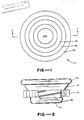
- an assay device designated by the number 10 is illustrated in the form of container means defining a hollow interior space or chamber 12 of variable volume.
- container means comprises a hollow body 14 and piston means 16 mounted for movement into and out of the body upon relative movement between the piston means and body.
- Piston means 16 serves as movable wall means forming a part of the container means for varying the volume of chamber 12.
- body 14 has a generally U-shaped vertical cross-section and a circular horizontal cross-section.
- Side wall 14a of the U defines a gripping surface in the form of a rim of generally rectangular cross-section disposed at the upper part of the arms of the U.
- the base portion of the U has a substantially longer diameter than the height of the arms.
- body 14 includes a spiral groove 14b in which the mating threads of piston means 16 as described below.
- Body 14 is suitably formed of a disposable plastic material such as polyethylene, polypropylene, polystyrene or polyvinyl chloride, or of a durable material such as a metal (e.g., aluminum) which permits reuse of device 10, if desired.
- Piston means 16 comprises a circular piston member 18 with an externally accessible gripping surface 18a.
- Piston 18 includes a circular upright wall portion 18b which, with body 14, defines chamber 12. Wall portion 18b forms a rim for the containment of liquid in chamber 12.
- Piston member 18 further includes an inwardly projecting circular ridge 18c serving to seat an inwardly projecting convex inner wall of adjacent annular retaining insert 20.
- Piston member 18 also includes an O ring run 18d in which is seated a pliable O ring 22, suitably formed of rubber.
- Piston member 18 also defines a spiral externally projecting thread 18e which is seated within spiral groove 14b of body 14.
- Membrane means 24 is retained within the open center of piston member 18 by pressure fit within insert inner wall 20a.
- membrane means 24 includes a porous membrane in the form of a membrane disc 24a with an externally visible upper surface and an independent porous support disc 24b disposed adjacent and interior of membrane 24a, also retained by insert wall 20a.
- variable chamber 12 approximately at minimum volume.
- piston member 18 By gripping surfaces 14a and 18a, piston member 18 can be twisted relative to body 14 to cause the piston member to be moved outwardly from the body and to increase the volume of chamber 12.
- Chamber 12 is substantially sealed from the environment except through membrane means 24.
- O ring 22 serves to retain a pressure seal against the inner wall of the body when piston member 18 is moved.
- the membrane of membrane disc 24a may be of any type capable of immobilizing reaction product of the reagents and sample component without adversely affecting the reaction, and which permits passage, without undue pressure drop, of the remainder of the liquid sample or of a washing solution.
- a suitable membrane is formed of nitrocellulose or nylon, although other types of membranes with these characteristics can be employed.
- the porosity of the membrane preferably varies from about 0.2 to about 12 microns.
- an immunological reagent is first immobilized on the membrane.
- the reagent immunologically reacts with and captures the predetermined component of the liquid sample to be detected.
- Such immunological reagent typically a protein such as an antibody or antigen, can be immobilized directly onto certain membranes, such as nitrocellulose, by absorption or by covalent bonding.
- the depth or thickness of the membrane is selected so that an adequate amount of immunological reagent can be immobilized to capture the sample component. However, the thickness should not be so great as to cause undue pressure drops by the passage of the liquid sample through the membrane.
- a suitable thickness for the membrane is from 100 microns to 200 microns.
- Membranes of the above thickness when subjected to pressure forces applied by the present device may not have adequate strength to resist tearing or collapsing into chamber 12. Accordingly, it is preferably to include porous support disc 24b between membrane 24a and chamber 12. It may be separate from the membrane or bonded to it, if desired. Support disc 24b may be formed of a flexible plastic material such as polyester or fiberglass, such as supplied by Glassrock Co., and is preferably more rigid than membrane 24a. It is preferably thicker than membrane disc 24a, typically ranging from 1mm to 2mm. It is sufficiently porous so that it does not create undue pressure drops when the liquid sample moves into and out of chamber 12.
- Support disc 24b may carry a dry reagent which is soluble in the liquid sample. When the liquid sample flows through disc 24b, it dissolves the reagent for flow to membrane 24a for reaction with the sample component. This saves the step of independently adding a further component.
- a sandwich assay for an antigen one antibody is immobilized on membrane 24a and a soluble labeled antibody is deposited in dry form on support disc 24b, as by lyophilization directly on the support disc. Passage of liquid sample through the support disc carries with it the soluble label antibody which forms a sandwich with the corresponding sample as it is present.
- the soluble dry reagent may be deposited on some other portion of the assay device exposed to chamber 12 and so which contacts liquid sample.
- the assay device of the present system broadly is used to determine a predetermined component of a liquid sample with at least one reagent to form a detectable product on membrane disc 24a as an indication that the component is present in the sample.
- the liquid sample is contacted on one side of membrane means 24 and the chamber volume is varied to selectively cycle the liquid sample through the membrane means into and out of the chamber.
- the chamber is substantially free of absorbent material.
- the system is particularly applicable to an immunoassay wherein the sample component is one component of an immunological pair including antigens, antibodies, or haptens.
- the immunological pair includes two components which immunologically bond to each other.
- Specific immunological pairs include antigens and their antibodies (monoclonal antibodies or polyclonal antibodies), biologically functional haptens and their antibodies, enzymes and their substrates, hormones and their receptors, vitamins and their receptors, biotin and either avidin or an antibody to biotin, and lectin and its specific binding mono,di- or trisaccharide.
- the liquid sample is biologically derived, (e.g., urine or serum) and the one reagent comprises a labeled antigen or antibody.
- the one reagent is a labeled antibody specific for the predetermined antigen in the sample.
- This system uses a second reagent, a capture antibody also specific for the predetermined antigen, immobilized on membrane disc 24a prior to addition of the liquid sample to the device.
- immobilizing proteins such as monoclonal or polyclonal antibodies to solid surfaces such as membrane disc 24a without deactivation are well known. See e.g., Schuurs U.S. 3,551,555 and Hendry et al., J. Immun. Methods, 35 1980, 285.
- proteins may be immobilized by covalent bonding, e.g., as described in U.S. 3,720,760.
- the amount of protein immobilized per unit area of nylon is greater than that for nitrocellulose.
- the labeled antibody or antigen described with respect to the sandwich assay may be any of the conventional types including radioactive, enzyme, or a metal complex label which are conjugated to the antibody. Formation of conjugates between such immunological substances and labels are well known, e.g., (a) radioactive labels - U.S. 3,646,346, Hunter et al., Nature 142 (1962), 945, (b) enzyme labels - U.S. 3,654,090, 3,791,931 and 3,817,838, Wilson et al., Immunoflourescense and Related Staining Techniques, Knapp., W. et al., Eds. L.
- the presence of the enzyme label in the reaction product on the surface of the membrane is detected by contact of the enzyme with a substrate in solution which produces a color upon reaction with the enzyme.
- the liquid sample may be discarded and the substrate contacted thereafter with the reaction product on the membrane.
- the substrate solution may be deposited onto the external surface of the membrane and passed through it by suction created by increasing the volume of chamber 12. Alternatively, it may be initially placed in the chamber and forced out of it by decreasing the chamber volume. Then, the color formed by the substrate is visible on the membrane from its externally exposed side.
- Colloidal gold conjugates useful for probes such as cytochemical markers are well known for microscopy. See, e.g., Scanning Electron Microscopy , 1981, II, pp. 9-31, "Immunocytochemistry” Eds. Polak, J.N., et al., Bristol, London, Boston (1982) pp. 82-112, and Journal of Neuroscience Methods , 7(1983), pp.1-18.
- Colloidal gold particle markers are simple to use in comparison to other conventional markers. For example, they do not require instruments necessary for detection of other markers such as radioactive isotopes. Furthermore, unlike enzymes, they do not require the additional step of adding substrate.
- a technique for enhancing the sensitivity of the gold complex may be employed such as disclosed in Holgate, C.S., et al., J. Histochem. Cytochem 31:938 (1938) and in Dancher, G, et al., J. Histochem. Cytochem 31:1394 (1983).
- This system is an "indirect" technique employing an immunological reagent, immunoglobulin, absorbed to colloidal gold. The gold particles are revealed by a silver precipitation reaction.
- the silver enhancement takes advantage of the catalytic effect of gold to catalyze the photographic physical developer process converting silver ion to silver metal.
- Suitable colloidal gold or gold sol particle size is from 3nm to 150nm.
- This immuno gold- silver staining method may have an enhanced sensitivity of up to 200-fold in comparison to the use of the gold particles without silver staining.
- the increased sensitivity permitted by cycling is clear from a theoretical model of the immobilized immunological reagent contact with the sample component.
- the immunological reagent in this instance, antibody, is immobilized on the membrane either by absorption or covalent bonding.
- the antibody is exposed to the channels or pores of the membrane and is only capable of capturing antigen in passing sample which is proximate to the antibody. Cycling the sample to permit contact of different sample portions flowing through the membrane pores provides substantially increased chances for reaction between the antigen and the immobilized antibody, thereby not only increasing the sensitivity of the assay but also its speed.
- the mixing effect of cycling is particularly apparent when the immunological reagent is concentrated at a specific region, such as a dot on the membrane, as described below.
- the immobilized antibody is only deposited at that one dot.
- only the antigen in the sample in an imaginary column above the dot contacts the antibody.
- the remaining antigen in the sample passes through the membrane without such contact.
- there is continuous mixing of different sample portions cycling antigen which causes exposure of significantly more antigen to the immobilized antibody on the membrane with the above advantageous results.
- This principle of increased mixing efficiency applies to any of the conventional immunoassays with respect to which the present system may be employed.
- the increased efficiency or interaction increase the local concentration of reactants which, in turn, increases the reaction kinetics.
- the labeled antibody may be added simultaneously with the sample or may be added before or after the addition of sample.
- the labeled antibody is deposited in dry form retained on the porous support disc 24b prior to addition of the liquid sample. Then, when the sample flows in either direction through membrane 24a, it dissolves the labeled antibody so that it reacts with antigen if present in the sample to form a sandwich of immobilized antibody.antigen.labeled antibody on the surface of membrane 24a.
- the system is also applicable to the detection of antibody by reversal of the antigen and antibody to form a sandwich of immobilized antigen.antibody.labeled antigen (or anti-antibody).
- support disc 24b As mentioned above, a step in the analysis is eliminated by the predeposit of labeled antibody on the support disc. This is possible because the liquid sample is cycled backward and forward through the membrane.
- support disc 24b By forming support disc 24b of an opaque material, detectable label in the liquid sample retained in chamber 12 is not visible on the external exposed surface of membrane 24a and so it does not interfere with signal produced on the upper surface. In effect, support disc 24b also serves as a visual mask between the background signal of unreacted labeled reagent in the chamber and the labeled reaction product on the membrane.
- the present invention is also applicable to the competitive binding technique.
- the corresponding member of the immunological pair i.e., antibody is immobilized on to the membrane surface.
- Antigen labeled in the manner described above of the same immunological character as the antigen to be detected in the sample is contacted with the immobilized antibody on the membrane.
- the immobilized antibody is in limited supply, and so a competition is set up between the antigen in the sample and the labeled anti body.
- the signal emitted from the label is inversely proportional to the amount of antigen in the sample.
- Such competitive binding technique using a membrane is described in Bagshawe U.S. 3,888,629.
- the competitive binding assay may be performed by reversing the roles of the antigen and antibody.
- the immobilized member of the immunological pair is the antigen for the detection of antibody in the sample which competes with labeled antibody.
- the competitive binding assay can be simplified by using the present system. That is, the labeled immunological reagent conjugate, e.g., antigen-label, can be coated onto porous support 24b in lyophilized form. When the liquid sample suspected of containing antigen contacts the support, it dissolves the labeled antigen and carries it to membrane 24 at which the competition between the sample antigen and labeled antigen is set up for the limited supply of antibody at the membrane surface.
- the labeled immunological reagent conjugate e.g., antigen-label
- the immunoassays which have been described are the sandwich assay and the competitive binding assay. It should be understood that the system is also useful for other immunoassays such as, for example, described in U.S. 4,366,241.
- the substances to be analyzed include a wide variety of biologically derived substances, e.g., proteins. The following is a list of some of these substances. (The listed substances also include immunologically reactive antibodies, and fractions of the substances.
- Corticotropin (ACTH) (adrenocorticotropic hormone) Follicle-stimulating hormone Luteinizing hormone (interstitial cell-stimulating hormone) Parathyroid hormone Prolactin Chorionic Gonadotropin Insulin Glucagon Relaxin Somatropin Triiodothyronine Thyrocalcitonin Thyroxine
- Adinoviruses Arboviruses Eastern Equine Eucephalitis Virus Western Equine Eucephalitis Virus Sindbis Virus Semliki Forest Virus St. Louis Encephalitis Virus California Encephalitis Virus Colorado Tick Fever Virus Yellow Fever Virus Dengue Virus Hepatitis Hepatitis A Virus Hepatitis B Virus Herpes Viruses Herpes simplex, Types I and II Varicella (Chicken pox) Cytomegalovirus Myxoviruses Influenza (A, B, and C) Parainfluenza (1-4) Mumps virus Newcastle Disease Virus Measles Virus Canine Distemper Virus Respiratory Syncytial Virus Rubella Virus Picornaviruses Poliovirus Coxsackievirus Echoviruses Rhinoviruses Pox Viruses Vaccinia Molluscum contagiosum
- the system is also applicable to other assay systems which are not categorized as immunoassays, e.g., the detection of unknown DNA sequences.
- liquid sample containing the unknown DNA sequence is passed through the membrane and immobilize on the membrane as by contact with DNA previously immobilized on the membrane.
- a labeled DNA probe passed in a liquid through the membrane. If hybridization occurs, the labeled DNA probe will be retained in detectable form on the membrane surface.
- This system is described in Polsky-Cynkin, R., et al., Clin. Chem. 31/9, 1438 (1985).
- the immunological reagent is concentrated on at least one defined region on the membrane which appears as a dot but which actually extends through the membrane in a column of a diameter approximately equal to the dot. Referring to a sandwich or competitive binding techniques, this is accomplished by immobilizing the capture immunological reagent, e.g., antigen or antibody, only in such region by flowing the reagent to be immobilized through the membrane thickness. The reaction with the sample component and with the labeled reagent only occurs in that region.
- the capture immunological reagent e.g., antigen or antibody
- the dot approach has certain advantages such as the performance of multiple simultaneous assays with a single device as described below. Also it provides a more distinctive end product signal since it is concentrated at a single region.
- the ability to cycle the sample through the membrane greatly increases the mixing efficiency of the sample and immobilized immunological reagent.
- a conventional once-through system only the immunological component in the sample exposed to the dot is the imaginary liquid column directly above the dot. Cycling through the membrane permits the immunological component in the remainder of the liquid sample to contact the immobilized reagent to concentrate the sample and labeled reagent. This can permit the detection of a label such as colloidal gold without instrumentation where it would not otherwise be detectable.
- Another advantage of the dot approach is that it permits the simultaneous detection of multiple components in a sample. For example, with a single assay device, two different antibodies specific for predetermined different antigens can be immobilized on distinct spots on the membrane. The sample suspected of containing either one of the antigens is then contacted with the membrane and with labeled antibody specific for the two different membranes. A signal produced by the labels at one or the other of the dots indicates the presence or absence of one or both of the antigens.
- the dots may be distinguished from each other by their location or by an identification near each immobilized antibody dot. Thus, for example, if a color appears at the first dot but not the second, the first antigen but not the second antigen is present. If both dots appear, then both antigens are present, and if no dots appear, neither antigen is present. Alternatively, the label may be selected to produce different colors at each of the dots.
- This system could be expanded to include the simultaneous detection of more than two components of the liquid sample by a corresponding number of immobilized immunological reagent on the membrane.
- a first antibody is reactive with a particular subunit of a number of different antibodies. If a second antibody is specific for a subunit of one antigen only, such second antibody can be used as the immobilized antibody and a single labeled first antibody can be used as the universal labeled antibody for antigen of interest.
- the standard protocols for the conventional immunoassays may be used in the present invention.
- the order of addition of the sample and labeled reagents may be simultaneous or sequential.
- the flow rate of liquid through the membrane is controlled by the pressure in chamber 12.
- the rate of increase in the volume of evacuated chamber 12 causes a corresponding increase in the flow rate through the membrane.
- the liquid flow rate through the membrane is controlled by the rate of decreasing the volume of the chamber.
- Typical flow rates through the membrane using the present device are on the order of 0.5 ml/second depending on the porosity of the membrane and viscosity of the fluid.
- Modification of the specific device illustrated may be made in accordance with the present invention so long as a membrane is substantially sealed across an opening into a variable volume chamber and means is provided for readily varying the volume of such chamber.
- the piston could be a slideably received plunger within the body to vary the volume of the chamber with a non-twisting push and pull force applied to the piston or body.
- a stop may be included to prevent disengagement of the body and piston during normal cycling of the liquid.
- there are certain advantages in permitting the ready disengagement of the piston and body so that the liquid in the chamber can be readily emptied without passage through the membrane or such liquid may be placed in the chamber in the first instance.
- other more elaborate means may be provided for varying the volume of the chamber.
- a slideable plunger or piston assay device designated by the number 30, is illustrated.
- the slideable piston is used instead of the screw threaded piston of the embodiments of Figs.. 1-3.
- the device includes three separate functional portions which are mated together during operation.
- piston means 32 including a piston housing 34 within which a piston plunger 36 is slideably received.
- Housing 34 includes a tip 34b.
- Plunger 36 includes a handle portion 36a at one end, piston rod 36b and a slideable piston head 36c with a flexible rubber perimeter which forms the slideable seal with the inner wall of cylindrical housing 36.
- piston means 32 is in the form of a hypodermic syringe.
- the interior wall of housing 34 and the forward side of piston head 36c define a chamber 37 of variable volume sealed from the exterior except through outlet port 34b.
- membrane means 38 is in a self-contained housing 40 formed independently of piston means 32.
- a conventional hypodermic syringe can be used in combination with the membrane means by a simple force fit.
- the two parts can be integrally formed.
- Housing 40 includes an inlet port 42 and an outlet port 44.
- housing 40 is formed of support walls 46 and support wall 48 integrally connected to transverse upright walls 50 and 52 through which project inlet and outlet ports 42 and 44, respectively.
- Sandwiched between flat walls 46 and 48 is membrane 54.
- One, and preferably both, of walls 46 and 48 are either totally transparent or include a window of transparency so that membrane 54 can be viewed from the exterior of the device.
- Walls 46 and 48 are formed with adjacent stepped ridges and grooves defining parallel channel 46a and 46b, respectively, aligned with the direction of flow of fluid entering port 42 from the syringe. Each of the channels terminates adjacent abutting wall 52 so that the only path of fluid entering inlet port 42 is through membrane 54 and out outlet port 44.
- the liquid exiting port 44 can be collected in a suitable receptacle such as test tube 56.
- outlet port 44 may mate with a port of an enclosed vessel for ready withdrawal of the fluid on the application of suction force by piston means 34, as described below.
- membrane 54 corresponds to membrane 24a.
- the same type of reactions set forth above may be performed on membrane 54, including the use of the dot technique. Since walls 46 and/or 48 are transparent, the reaction product including a detectable label visible to the eye through the transparent wall.
- the liquid initially is deposited in receptacle 56 and tip 34b is immersed.
- Plunger 36 is fully inserted in housing 34 so that chamber 37 is at minimum volume. Then, plunger 36 is withdrawn to increase the volume of chamber 37 and create suction which draws fluid from receptacle 56 through port 44 and channels 48a to pass across membrane 46 into channels 46a and out port 42 into variable chamber 37.
- the liquid sample may be initially in place in chamber 37 and forced under pressure through port 34b into port 44 and channels 46a across membrane 54 and channels 48a into outlet port 44 into receptacle 56.
- the fluid may be cycled back and forth through membrane 54 to increase the mixing efficiency.
- FIG. 7 another embodiment of the invention is illustrated in which the device of Fig. 1 is modified so that the piston member is mounted for slideable rather than twisting movement.
- the assay device is illustrated in the form of container means 60 defining a hollow interior space or chamber 62 of variable volume.
- Container means 60 includes a hollow body 64 and piston means 66 mounted for movement into and out of the body upon relative sliding movement between the piston means and body.
- body 64 is a generally U-shaped vertical cross-section and a circular horizontal cross-section.
- Body 64 may be suitably formed of the same materials as body 14 of Fig. 1.
- Piston means 66 includes a circular piston member 70 with an exterior upright wall portion 70a and an annular recess 70b for O-ring 70 which serves to retain a pressure seal against the inner wall of body 64 when piston member 70 is moved.
- Piston member 70 also includes an inner wall 70c which with horizontal bottom portion of body 64, defines chamber 62.
- Piston member 70 also includes another annular opening 70d within which is fitted spring means in the form of coil spring 74 which is fully compressed in Fig. 7. When the pressure is released, spring 74 will move piston member 70 upward and out of body 64 to expand chamber 62.
- An optional top 76 is provided with a downwardly projecting rim to be seated against the corresponding shoulder of body 64 to facilitate pressing piston member 70 toward body 64.
- Membrane means 78 is retained in the open center of piston number 64 by pressure fit against lower projecting portion of piston wall segment 70e.
- membrane means 78 includes a circular porous membrane in the form of a membrane disk with an externally visible upper surface and independent support below it.
- Membrane 78 may be unitary or segmented as illustrated and may take the form described with respect to membrane 24 above.
- the device of Fig. 7 is illustrated with chamber 62 at the minimum volume.
- the spring will cause the volume of shoulder 62 to expand as desired.
- the system may be operated substantially as described with respect to the device of Fig. 1.
- a push-button device 80 is illustrated which also functions on the variable volume principle described above.
- Device 80 includes an upper housing 82 which pivots from a lower housing 84 about a rod 86 which serves as a pivot point.
- Lower housing 84 is permanently fixed to rod 86 as by a force fit while housing 86 is free to rotate to form a horizonal to a vertical position, if desired, to permit the flow of liquid into the device.
- Upper housing 84 includes a push-button or bulb 88 formed of a resilient, collapsible material such as rubber, mounted to the remainder of upper housing 82 by welding or the like. Bulb 88 defines a variable volume chamber 90. Bulb 88 is suitably sealed with the remainder of upper housing 82 by welding or the like. Upper housing 82 also includes a dome portion 92 which may be rigid and which defines a fixed volume chamber 94 and which includes an opening 96 to release excess pressure. Below chamber 94 is mounted membrane means 98 suitably retained in place by a gasket 100. Since the reaction product is viewed on membrane 98 through the top of dome 92, it should be transparent, or at least translucent.
- Upper housing 82 also includes a flexible L-shaped locking portion 102 which fits into a corresponding rim 84a of lower housing 84 to retain the unit in a closed position until it is desired to reopen it.
- the system can be readily unsealed by pivoting locking portion 102 away from shoulder 84a and then pivoting upper housing 82.
- Interconnecting chamber 90 and 94 is a flow channel or bore 104 formed between the upper and lower housings in the form of a circular bore or the like communicated between chamber 90 and the lower portion of the membrane means 98.
- either chamber 90 or 94 may be partially filled with liquid prior to closing the system.
- bulb 88 is pushed downwardly to reduce the volume of chamber 90 and to cause the liquid to flow through membrane means 98 into chamber 94.
- the pressure on bulb 88 is released and the solution is drawn under the thus-created reduced pressure back into chamber 90. If the liquid initially is in chamber 90, it is pushed in the first pass through membrane 98 under positive pressure rather than vacuum and is only drawn back into chamber 90 by reduced pressure caused by released of the bulb. Similar assays may be performed as described regarding the device of Fig. 8.
- the device of Fig. 9 is similar to that of the one of Fig. 4 in that the driving force may be provided by a conventional or modified syringe which may be integral or removable from the device of figure 4.
- the device generally designated by the number 110, includes an upper housing portion 112 and a lower housing portion 114 which are retained as an integral piece by fusion at the interfaces or the like.
- the device defines an open end 116 where it is in sealing engagement with a syringe 118.
- the syringe includes a piston housing 120 within which the piston plunger 122 is slideably received.
- piston plunger 122 includes a ring 122a for convenient holding of the device in one hand and movement of the piston into and out of piston housing 120.
- piston rod 122 b and the slideable piston head 122c Piston body 120 includes a tip 120a which forms a removable seal with the wall defining opening 116.
- Membrane means 124 is mounted between upper and lower housings 112 and 114, respectively, in cooperation with gasket 128. Rigid chambers 130 and 132 communicate with each other on opposite sides of membrane means 124.
- a solution initially within chamber 120b defined to the forward side of piston head 122c is forced under pressure through channel 134 into chamber 130 downwardly and through membrane means 124 and into chamber 132.
- piston head 122 is pulled in the opposition direction by ring 122a to create a reduced pressure in chamber 120b to cause the liquid to be drawn back and upwardly through the membrane through chamber 130.
- the reaction product is viewed on the upper surface of membrane means 124 and so the portion of upper housing 112 above the member is transparent.
- Device 140 includes an opening 142 which seals against tip 120a of the syringe and communicates with a chamber 144 across membrane 146 into lower chamber 148 and through open channel 150.
- channel 150 may be placed into the test tube from which a solution may be drawn by pulling ring 122a to the left and creating reduced pressure in chamber 120b.
- the device of Fig. 11 designated by the number 160 is also operable with a removeable syringe. As illustrated, it is disposed within a test tube 162 from which it may draw solution as described.
- Device 160 includes a lower body 164, an upper body 166, and membrane means 168 which is retained therebetween.
- Body 166 defines a channel 170 between tip 120a and the lower side of membrane means 168.
- the lower body 164 is generally tubular in external shape while upper body 166 is generally of circular plug shape with an open central circular area through which the upper upper portion of the membrane may be viewed.
- the liquid initially is within the syringe or within test tube 162 and may be forced to flow in either direction through membrane means 168 as described above.
- a modification of the device of Fig. 11 is illustrated with a seal is formed with an external container for the device.
- the device 180 includes a hollow tubular member 182 with stepped inner dimensions. A slight taper is provided so that the tip 120a is pressure fit to form a seal within one segment of the device.
- Tubular member 182 defines a narrow channel 184 into a lower chamber 186 below membrane means 188.
- An upper circular piece 190 of similar construction to piece 166 in Fig. 11 is provided to retain membrane means 188 in a seated sealed position.
- the exterior of tubular member 182 includes a stepped outer diameter which is forcefit for removeable sealing engagement and exterior transparent tube 192.
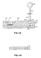
- the device of Figs. 13 and 14, generally designated by the number 200, includes an upper housing portion 202 and a lower housing portion 204 defining therebetween a central bore 206.
- Upper housing portion 202 defines a tapered circular hole 208 within which tip 120 b of the syringe is forcefit for sealing engagement.
- Membrane means 210 is force fit by an annular plastic retaining ring 212 into a horizontal position in upper housing portion 202. Such surface is externally visible since ring 212 define open space to its interior.
- membrane means 210 includes three layers, an upper layer 210a which may be formed of paper-backed nitrocellulose, polyester backed nitrocellulose, nylon or modified nylon, middle layer 210b, a filter, which may be formed of the same materials, and a lower support disc 210c which may be formed of porous plastic, fiberglass or the like.
- a single layer may be used. Any of the layer may be impregnated with lyophilized reagent such as a colloidal gold conjugate.
- the device of Figs. 13 and 14 operates by forcing liquid from the syringe through central bore 206 upwardly through membranes means 210.
- the liquid may move in the opposite direction by withdrawing the piston of the syringe.
- a sandwich immunoassay is illustrated for the antigen human chorionic gonadotropin (hCG) in a urine sample containing a known amount of hCG.
- Monoclonal antibodies were used for the immobilized reagent and for the labeled reagent.
- the labeled conjugate comprises a gold sol based upon the procedure of Faulk, W.P., et al. Immunochem. 8:1081 (1971). Briefly summarized, 100ml distilled water containing 0.01% chloro-auric acid solution is mixed with 4ml of 1% trisodium citrate and boiled for 15 minutes. The solution turns from yellow to red at an optical density at 520nm of about 1.
- the other immunological reagent is an anti-alpha chain hCG monoclonal antibody supplied Medix Biotech, Inc..
- a membrane disc 24a supplied by Schleicher and Scherell, 0.45 microns porosity and 140 microns thick
- the anti-alpha monoclonal antibody (1 ⁇ l) is applied to the disc at a concentration of 1 mg/ml in a limited area of about 203mm diameter.
- the innoculated disc is then incubated with BSA in phosphate buffered saline solution and placed into the device described above.
- Monoclonal antibody to the beta chain of hCG (supplied by Miles Laboratories) is conjugated with this gold sol and is coated onto the porous disc 24b and is frozen in a -50°F temperature bath. Then it is freeze-dried.
- a 500 microliter urine sample is placed onto the top of the membrane with chamber 12 of its minimum volume as illustrated in Fig. 3a. Then the piston is turned relative to the body to cause the chamber to expand as illustrated in Fig. 3b. The sample solution is then drawn through both membrane 24a and porous support disc 24b containing the lyophilized labeled antibody. During passage through disc 24a, the labeled antibody is dissolved in the urine. Then, piston member 16 is twisted into the opposite direction to force the urine sample out of the chamber through the membrane. This cycle is repeated a number of times with increasing color during each cycle. In this way, the sensitivity of the assay is increased by cycling the liquid through the membrane. This permits the visual reading of a red dot on the membrane using colloidal gold particles at antigen concentrations where this would not normally be done.
- a sandwich assay is performed in which antigen is immobilized on the membrane, an antibody component of a serum sample is to be analyzed, and labeled antibody lyophilized on the plastic support disc is a conjugate of an anti-antibody to the sample antibody labeled with colloidal gold formed in the manner described above.
- the antigen, M.pneumoniae is impregnated onto a nitrocellulose membrane disc as described in Example 1.
- a positive reaction is indicated by a distinct red dot on the membrane.
- Example 2 the procedure of Example 2 is followed, except that the membrane disc includes two different dots, one containing M.pneumoniae antigen and the other Adenovirus antigen. If the serum sample contains antibody to M.pneumoniae alone, a single dot in a pre-selected position is obtained similarly. If the serum contains antibodies to adenovirus alone, a single dot at another predetermined position is indicated. If it contains antibodies to both M.pneumoniae and adenovirus two dots will appear. If it contains antibodies to neither, no dots will appear.
- a competitive binding assay is performed for thyroxine antigen.
- the thyroxine a hapten
- the conjugate is formed by reacting the thyroxine with colloidal gold conjugate through spacer arms formed of horseradish peroxidase.
- a saturated solution of thyroxine sodium salt in 0.1M sodium bicarbonate solution (10ml) at pH 9.5 is conjugated through horseradish peroxidase using the procedure of Nakane, P.K., J. Histochem Cytochem, 14:929 (1966).
- the thyroxine solution is used instead of the protein described in Nakane.
- the solution is dialyzed against distilled water to remove excess thyroxine.
- the thyroxine-horseradish peroxidase conjugates are linked to 10nm colloidal gold particles and then centrifuged to remove excess non-conjugated free thyroxine-horseradish peroxidase. The residue is resuspended in buffer.
- the anti-thyroxine antibody is immobilized on the membrane as follows: Affinity purified rabbit anti-thyroxine antibodies in pH 7.4, 0.01M phosphate buffered saline coated onto a spot on the nitrocellulose membrane is described in Example 1. The concentration of antibody is 100 ⁇ g/ml.
- 0.1 ⁇ l of the labeled thyroxine and sample containing different known concentrations (1, 5, 10 and 20ng/ml) of thyroxine is applied to the top surface of the membrane 24a of Fig. 1.
- Different colors are produced at the different concentrations of thyroxine, a more intense color corresponding to a lower concentration of thyroxine.
- an unknown sample is analyzed and compared against the colors produced by the known concentrations described above.
Priority Applications (1)
| Application Number | Priority Date | Filing Date | Title |
|---|---|---|---|
| AT87303647T ATE78099T1 (de) | 1986-04-24 | 1987-04-24 | Testsatz mit veraenderlichem volumen und verfahren. |
Applications Claiming Priority (2)
| Application Number | Priority Date | Filing Date | Title |
|---|---|---|---|
| US85573086A | 1986-04-24 | 1986-04-24 | |
| US855730 | 1986-04-24 |
Publications (3)
| Publication Number | Publication Date |
|---|---|
| EP0246760A2 true EP0246760A2 (fr) | 1987-11-25 |
| EP0246760A3 EP0246760A3 (en) | 1988-06-08 |
| EP0246760B1 EP0246760B1 (fr) | 1992-07-08 |
Family
ID=25321945
Family Applications (1)
| Application Number | Title | Priority Date | Filing Date |
|---|---|---|---|
| EP87303647A Expired - Lifetime EP0246760B1 (fr) | 1986-04-24 | 1987-04-24 | Dispositif d'essai à volume variable et méthode |
Country Status (5)
| Country | Link |
|---|---|
| EP (1) | EP0246760B1 (fr) |
| JP (1) | JPS6324156A (fr) |
| AT (1) | ATE78099T1 (fr) |
| CA (1) | CA1291948C (fr) |
| DE (1) | DE3780213D1 (fr) |
Cited By (23)
| Publication number | Priority date | Publication date | Assignee | Title |
|---|---|---|---|---|
| GB2198848B (en) * | 1986-12-15 | 1990-10-31 | Pall Corp | Vacuum diagnostic device |
| EP0419168A2 (fr) * | 1989-09-18 | 1991-03-27 | La Mina Ltd. | Appareil de collection d'essais d'échantillons de fluides |
| EP0458198A2 (fr) * | 1990-05-22 | 1991-11-27 | Millipore Corporation | Dispositif d'analyse à écoulement |
| EP0508010A1 (fr) * | 1991-04-10 | 1992-10-14 | La Mina Ltd. | Module membraneux pour tester des liquides biologiques et méthode pour leur application |
| WO1993009431A1 (fr) * | 1991-11-01 | 1993-05-13 | The University Of Birmingham | Dispositif d'analyse |
| US5358690A (en) * | 1989-01-10 | 1994-10-25 | Lamina, Ltd. | Environmental sample collection and membrane testing device |
| EP0654972A1 (fr) * | 1992-07-28 | 1995-05-31 | GUIRGUIS, Raouf A. | Procede et appareil permettant d'obtenir des monocouches cytologiques |
| WO1995014533A1 (fr) * | 1993-11-24 | 1995-06-01 | Abbott Laboratories | Procede et appareil pour recueillir un echantillon cellulaire contenu dans un echantillon liquidien |
| EP0674009A2 (fr) * | 1994-03-14 | 1995-09-27 | Becton, Dickinson and Company | Procédé et dispositif d'amplification d'acide nucléique |
| US5725831A (en) * | 1994-03-14 | 1998-03-10 | Becton Dickinson And Company | Nucleic acid amplification apparatus |
| WO1999007472A1 (fr) * | 1997-08-07 | 1999-02-18 | Minnesota Mining And Manufacturing Company | Dispositif permettant de maintenir des echantillons |
| US5976824A (en) * | 1993-11-24 | 1999-11-02 | Abbott Laboratories | Method and apparatus for collecting a cell sample from a liquid specimen |
| WO2005090983A2 (fr) * | 2004-02-27 | 2005-09-29 | Board Of Regents, The University Of Texas System | Systeme de dosage a membranes comprenant des particules prechargees |
| WO2007072311A2 (fr) * | 2005-12-21 | 2007-06-28 | Koninklijke Philips Electronics N.V. | Détecteur pour biomolécules et procédé de préparation et d'utilisation de ce détecteur |
| WO2007072373A2 (fr) * | 2005-12-21 | 2007-06-28 | Koninklijke Philips Electronics N.V. | Détecteur pour biomolécules et procédé d'analyse faisant appel à ce détecteur |
| FR2917171A1 (fr) * | 2007-06-07 | 2008-12-12 | Biosynex Sarl | Methode de detection d'une molecule d'interet dans un echantillon liquide. |
| WO2010009734A1 (fr) * | 2008-07-21 | 2010-01-28 | Hounisen Laboratorieudstyr A/S | Système de fixation d'échantillon et procédé de fixation d'échantillons provenant d'humains et d'animaux sans fuite de fluide |
| WO2011067587A1 (fr) * | 2009-12-01 | 2011-06-09 | Health Protection Agency | Méthode et dispositif d'essai |
| EP2560004A1 (fr) * | 2011-08-19 | 2013-02-20 | DST Diagnostische Systeme & Technologien GmbH | Nouveau système de test PoC et procédé |
| ITTO20120730A1 (it) * | 2012-08-14 | 2014-02-15 | Fond Istituto Italiano Di Tecnologia | Dispositivo e metodo per determinare la cinetica di dissoluzione di nanoparticelle colloidali |
| EP2767831A1 (fr) * | 2013-02-19 | 2014-08-20 | DST Diagnostische Systeme & Technologien GmbH | Nouveau système de test PoC et procédé |
| CN107338184A (zh) * | 2017-08-02 | 2017-11-10 | 苏州博福生物医药科技有限公司 | 一种用于捕获细胞或溶液中生物分子的捕获筛及装置 |
| CN111157723A (zh) * | 2020-02-16 | 2020-05-15 | 广西中医药大学附属瑞康医院 | 一种新型冠状病毒的快速检测盒 |
Families Citing this family (6)
| Publication number | Priority date | Publication date | Assignee | Title |
|---|---|---|---|---|
| CA2406707A1 (fr) * | 2000-04-06 | 2001-10-18 | Robert Nagle | Dispositifs a circulation microfluidique et systemes avec couches de couverture integrees |
| WO2003090605A2 (fr) | 2002-04-26 | 2003-11-06 | Board Of Regents, The University Of Texas System | Methode et systeme permettant de detecter des facteurs de risque cardiaque |
| AU2004300168A1 (en) | 2003-12-11 | 2005-06-30 | Board Of Regents, The University Of Texas System | Method and system for the analysis of saliva using a sensor array |
| US8105849B2 (en) | 2004-02-27 | 2012-01-31 | Board Of Regents, The University Of Texas System | Integration of fluids and reagents into self-contained cartridges containing sensor elements |
| US8101431B2 (en) | 2004-02-27 | 2012-01-24 | Board Of Regents, The University Of Texas System | Integration of fluids and reagents into self-contained cartridges containing sensor elements and reagent delivery systems |
| CA2610793A1 (fr) | 2005-05-31 | 2007-05-10 | Labnow, Inc. | Methodes et compositions en rapport avec la determination et l'utilisation de la numeration de globules blancs |
Citations (3)
| Publication number | Priority date | Publication date | Assignee | Title |
|---|---|---|---|---|
| EP0093613A1 (fr) * | 1982-05-04 | 1983-11-09 | Syva Company | Procédé d'étalonnage simultané pour une méthode d'analyse immunologique hétérogène, dispositif et trousse de réactifs diagnostiques |
| DD231130A1 (de) * | 1984-09-24 | 1985-12-18 | Univ Berlin Humboldt | Mikrofiltrationsvorrichtung fuer praezipitate radioaktiv markierter makromolekuele und zellen |
| WO1986003589A1 (fr) * | 1984-12-07 | 1986-06-19 | Pharmacia Ab | Procede, appareil et systeme pour effectuer une analyse d'affinite biospecifique a l'aide d'une colonne munie d'une partie temoin |
-
1987
- 1987-04-23 CA CA000535386A patent/CA1291948C/fr not_active Expired - Fee Related
- 1987-04-24 JP JP62101688A patent/JPS6324156A/ja active Pending
- 1987-04-24 EP EP87303647A patent/EP0246760B1/fr not_active Expired - Lifetime
- 1987-04-24 DE DE8787303647T patent/DE3780213D1/de not_active Expired - Lifetime
- 1987-04-24 AT AT87303647T patent/ATE78099T1/de active
Patent Citations (3)
| Publication number | Priority date | Publication date | Assignee | Title |
|---|---|---|---|---|
| EP0093613A1 (fr) * | 1982-05-04 | 1983-11-09 | Syva Company | Procédé d'étalonnage simultané pour une méthode d'analyse immunologique hétérogène, dispositif et trousse de réactifs diagnostiques |
| DD231130A1 (de) * | 1984-09-24 | 1985-12-18 | Univ Berlin Humboldt | Mikrofiltrationsvorrichtung fuer praezipitate radioaktiv markierter makromolekuele und zellen |
| WO1986003589A1 (fr) * | 1984-12-07 | 1986-06-19 | Pharmacia Ab | Procede, appareil et systeme pour effectuer une analyse d'affinite biospecifique a l'aide d'une colonne munie d'une partie temoin |
Non-Patent Citations (1)
| Title |
|---|
| WO 86/03589 * |
Cited By (40)
| Publication number | Priority date | Publication date | Assignee | Title |
|---|---|---|---|---|
| GB2198848B (en) * | 1986-12-15 | 1990-10-31 | Pall Corp | Vacuum diagnostic device |
| US5358690A (en) * | 1989-01-10 | 1994-10-25 | Lamina, Ltd. | Environmental sample collection and membrane testing device |
| EP0419168A2 (fr) * | 1989-09-18 | 1991-03-27 | La Mina Ltd. | Appareil de collection d'essais d'échantillons de fluides |
| EP0419168A3 (en) * | 1989-09-18 | 1992-07-01 | Finger Diagnostics, Inc. | Fluid specimen collecting and testing apparatus |
| EP0458198A2 (fr) * | 1990-05-22 | 1991-11-27 | Millipore Corporation | Dispositif d'analyse à écoulement |
| EP0458198A3 (en) * | 1990-05-22 | 1992-11-19 | Millipore Corporation | Flow through assay apparatus and process |
| EP0508010A1 (fr) * | 1991-04-10 | 1992-10-14 | La Mina Ltd. | Module membraneux pour tester des liquides biologiques et méthode pour leur application |
| US5658531A (en) * | 1991-11-01 | 1997-08-19 | The University Of Birmingham | Assay device |
| WO1993009431A1 (fr) * | 1991-11-01 | 1993-05-13 | The University Of Birmingham | Dispositif d'analyse |
| EP0654972A1 (fr) * | 1992-07-28 | 1995-05-31 | GUIRGUIS, Raouf A. | Procede et appareil permettant d'obtenir des monocouches cytologiques |
| EP0654972A4 (fr) * | 1992-07-28 | 1996-05-29 | Raouf A Guirguis | Procede et appareil permettant d'obtenir des monocouches cytologiques. |
| WO1995014533A1 (fr) * | 1993-11-24 | 1995-06-01 | Abbott Laboratories | Procede et appareil pour recueillir un echantillon cellulaire contenu dans un echantillon liquidien |
| US5976824A (en) * | 1993-11-24 | 1999-11-02 | Abbott Laboratories | Method and apparatus for collecting a cell sample from a liquid specimen |
| EP0674009A2 (fr) * | 1994-03-14 | 1995-09-27 | Becton, Dickinson and Company | Procédé et dispositif d'amplification d'acide nucléique |
| EP0674009A3 (fr) * | 1994-03-14 | 1996-10-23 | Becton Dickinson Co | Procédé et dispositif d'amplification d'acide nucléique. |
| US5725831A (en) * | 1994-03-14 | 1998-03-10 | Becton Dickinson And Company | Nucleic acid amplification apparatus |
| AU689187B2 (en) * | 1994-03-14 | 1998-03-26 | Becton Dickinson & Company | Nucleic acid amplification method and apparatus |
| US5783148A (en) * | 1994-03-14 | 1998-07-21 | Becton Dickinson And Company | Nucleic acid amplification method and apparatus |
| WO1999007472A1 (fr) * | 1997-08-07 | 1999-02-18 | Minnesota Mining And Manufacturing Company | Dispositif permettant de maintenir des echantillons |
| WO2005090983A3 (fr) * | 2004-02-27 | 2005-11-17 | Univ Texas | Systeme de dosage a membranes comprenant des particules prechargees |
| WO2005090983A2 (fr) * | 2004-02-27 | 2005-09-29 | Board Of Regents, The University Of Texas System | Systeme de dosage a membranes comprenant des particules prechargees |
| WO2007072311A2 (fr) * | 2005-12-21 | 2007-06-28 | Koninklijke Philips Electronics N.V. | Détecteur pour biomolécules et procédé de préparation et d'utilisation de ce détecteur |
| WO2007072373A2 (fr) * | 2005-12-21 | 2007-06-28 | Koninklijke Philips Electronics N.V. | Détecteur pour biomolécules et procédé d'analyse faisant appel à ce détecteur |
| WO2007072311A3 (fr) * | 2005-12-21 | 2007-09-20 | Koninkl Philips Electronics Nv | Détecteur pour biomolécules et procédé de préparation et d'utilisation de ce détecteur |
| WO2007072373A3 (fr) * | 2005-12-21 | 2007-10-18 | Koninkl Philips Electronics Nv | Détecteur pour biomolécules et procédé d'analyse faisant appel à ce détecteur |
| FR2917171A1 (fr) * | 2007-06-07 | 2008-12-12 | Biosynex Sarl | Methode de detection d'une molecule d'interet dans un echantillon liquide. |
| WO2010009734A1 (fr) * | 2008-07-21 | 2010-01-28 | Hounisen Laboratorieudstyr A/S | Système de fixation d'échantillon et procédé de fixation d'échantillons provenant d'humains et d'animaux sans fuite de fluide |
| WO2011067587A1 (fr) * | 2009-12-01 | 2011-06-09 | Health Protection Agency | Méthode et dispositif d'essai |
| EP2560004A1 (fr) * | 2011-08-19 | 2013-02-20 | DST Diagnostische Systeme & Technologien GmbH | Nouveau système de test PoC et procédé |
| WO2013026808A1 (fr) * | 2011-08-19 | 2013-02-28 | Dst Diagnostische Systeme & Technologien Gmbh | Nouveau système de test poc, et procédé correspondant |
| ITTO20120730A1 (it) * | 2012-08-14 | 2014-02-15 | Fond Istituto Italiano Di Tecnologia | Dispositivo e metodo per determinare la cinetica di dissoluzione di nanoparticelle colloidali |
| WO2014027323A1 (fr) * | 2012-08-14 | 2014-02-20 | Fondazione Istituto Italiano Di Tecnologia | Dispositif et procédé pour la détermination de la cinétique de dissolution de nanoparticules colloïdales |
| EP2767831A1 (fr) * | 2013-02-19 | 2014-08-20 | DST Diagnostische Systeme & Technologien GmbH | Nouveau système de test PoC et procédé |
| WO2014128184A1 (fr) * | 2013-02-19 | 2014-08-28 | Dst Diagnostische Systeme & Technologien Gmbh | Nouveau système de test au poste de soins et procédé correspondant |
| CN104995515A (zh) * | 2013-02-19 | 2015-10-21 | Dst诊断系统与技术有限公司 | 新的床旁检测系统和方法 |
| US10168324B2 (en) | 2013-02-19 | 2019-01-01 | Dst Diagnostische Systeme & Technologien Gmbh | POC test system and method |
| US11353451B2 (en) | 2013-02-19 | 2022-06-07 | Dts Diagnostische Systeme & Technologien Gmbh | PoC test system and method |
| CN107338184A (zh) * | 2017-08-02 | 2017-11-10 | 苏州博福生物医药科技有限公司 | 一种用于捕获细胞或溶液中生物分子的捕获筛及装置 |
| CN111157723A (zh) * | 2020-02-16 | 2020-05-15 | 广西中医药大学附属瑞康医院 | 一种新型冠状病毒的快速检测盒 |
| CN111157723B (zh) * | 2020-02-16 | 2023-07-04 | 广西中医药大学附属瑞康医院 | 一种新型冠状病毒的快速检测盒 |
Also Published As
| Publication number | Publication date |
|---|---|
| EP0246760B1 (fr) | 1992-07-08 |
| ATE78099T1 (de) | 1992-07-15 |
| DE3780213D1 (de) | 1992-08-13 |
| JPS6324156A (ja) | 1988-02-01 |
| EP0246760A3 (en) | 1988-06-08 |
| CA1291948C (fr) | 1991-11-12 |
Similar Documents
| Publication | Publication Date | Title |
|---|---|---|
| EP0246760B1 (fr) | Dispositif d'essai à volume variable et méthode | |
| EP0310406B1 (fr) | Dispositif et procédé diagnostique caractérisé par un courant dirigé | |
| US5169789A (en) | Device and method for self contained solid phase immunodiffusion assay | |
| AU709403B2 (en) | Diagnostic detection device and method | |
| US5474902A (en) | Semi-permeable capillary assay device | |
| US4770853A (en) | Device for self contained solid phase immunodiffusion assay | |
| AU693236B2 (en) | Test device and method for colored particle immunoassay | |
| US6087184A (en) | Opposable-element chromatographic assay device for detection of analytes | |
| US5788863A (en) | Apparatus and method for conducting an assay using reverse flow through a membrane | |
| US6528321B1 (en) | Opposable-element chromatographic assay device for detection of analytes in whole blood samples | |
| US6413784B1 (en) | Multi-sectioned fluid delivery devices for detecting target molecules by immunoassay | |
| US5759866A (en) | Device and method for assaying biological components in sample | |
| JPH01123149A (ja) | 金属ゾル捕捉イムノアッセイ法、それの使用のためのキットおよび捕捉される金属含有複合材料 | |
| JPH06504130A (ja) | 毛細管血液抗原試験装置 | |
| US6753189B1 (en) | Detection apparatus and method for the same | |
| CA2017329A1 (fr) | Dispositif de diagnostic en milieu renouvele comportant une membrane allongee et methode | |
| JP2001059845A (ja) | 乾式分析方法及び乾式分析要素 | |
| MXPA97008428A (es) | Dispositivo y metodo para la deteccion de diagnostico | |
| CA2052909A1 (fr) | Dispositif servant a executer un dosage manuel rapide |
Legal Events
| Date | Code | Title | Description |
|---|---|---|---|
| PUAI | Public reference made under article 153(3) epc to a published international application that has entered the european phase |
Free format text: ORIGINAL CODE: 0009012 |
|
| AK | Designated contracting states |
Kind code of ref document: A2 Designated state(s): AT BE CH DE ES FR GB GR IT LI LU NL SE |
|
| PUAL | Search report despatched |
Free format text: ORIGINAL CODE: 0009013 |
|
| AK | Designated contracting states |
Kind code of ref document: A3 Designated state(s): AT BE CH DE ES FR GB GR IT LI LU NL SE |
|
| 17P | Request for examination filed |
Effective date: 19881107 |
|
| 17Q | First examination report despatched |
Effective date: 19900402 |
|
| GRAA | (expected) grant |
Free format text: ORIGINAL CODE: 0009210 |
|
| AK | Designated contracting states |
Kind code of ref document: B1 Designated state(s): AT BE CH DE ES FR GB GR IT LI LU NL SE |
|
| PG25 | Lapsed in a contracting state [announced via postgrant information from national office to epo] |
Ref country code: IT Free format text: LAPSE BECAUSE OF FAILURE TO SUBMIT A TRANSLATION OF THE DESCRIPTION OR TO PAY THE FEE WITHIN THE PRE;WARNING: LAPSES OF ITALIAN PATENTS WITH EFFECTIVE DATE BEFORE 2007 MAY HAVE OCCURRED AT ANY TIME BEFORE 2007. THE CORRECT EFFECTIVE DATE MAY BE DIFFERENT FROM THE ONE RECORDED.SCRIBED TIME-LIMIT Effective date: 19920708 Ref country code: LI Effective date: 19920708 Ref country code: GR Free format text: LAPSE BECAUSE OF FAILURE TO SUBMIT A TRANSLATION OF THE DESCRIPTION OR TO PAY THE FEE WITHIN THE PRESCRIBED TIME-LIMIT Effective date: 19920708 Ref country code: AT Effective date: 19920708 Ref country code: BE Effective date: 19920708 Ref country code: NL Effective date: 19920708 Ref country code: SE Effective date: 19920708 Ref country code: DE Effective date: 19920708 Ref country code: CH Effective date: 19920708 |
|
| REF | Corresponds to: |
Ref document number: 78099 Country of ref document: AT Date of ref document: 19920715 Kind code of ref document: T |
|
| REF | Corresponds to: |
Ref document number: 3780213 Country of ref document: DE Date of ref document: 19920813 |
|
| ET | Fr: translation filed | ||
| REG | Reference to a national code |
Ref country code: CH Ref legal event code: PL |
|
| PG25 | Lapsed in a contracting state [announced via postgrant information from national office to epo] |
Ref country code: ES Free format text: LAPSE BECAUSE OF FAILURE TO SUBMIT A TRANSLATION OF THE DESCRIPTION OR TO PAY THE FEE WITHIN THE PRESCRIBED TIME-LIMIT Effective date: 19921019 |
|
| NLV1 | Nl: lapsed or annulled due to failure to fulfill the requirements of art. 29p and 29m of the patents act | ||
| PG25 | Lapsed in a contracting state [announced via postgrant information from national office to epo] |
Ref country code: GB Effective date: 19930424 |
|
| PG25 | Lapsed in a contracting state [announced via postgrant information from national office to epo] |
Ref country code: LU Free format text: LAPSE BECAUSE OF NON-PAYMENT OF DUE FEES Effective date: 19930430 |
|
| PLBE | No opposition filed within time limit |
Free format text: ORIGINAL CODE: 0009261 |
|
| STAA | Information on the status of an ep patent application or granted ep patent |
Free format text: STATUS: NO OPPOSITION FILED WITHIN TIME LIMIT |
|
| 26N | No opposition filed | ||
| GBPC | Gb: european patent ceased through non-payment of renewal fee |
Effective date: 19930424 |
|
| PG25 | Lapsed in a contracting state [announced via postgrant information from national office to epo] |
Ref country code: FR Effective date: 19931229 |
|
| REG | Reference to a national code |
Ref country code: FR Ref legal event code: ST |