EP0246629A1 - Siebmaschine für pulverförmige, rieselfähige Stoffe - Google Patents
Siebmaschine für pulverförmige, rieselfähige Stoffe Download PDFInfo
- Publication number
- EP0246629A1 EP0246629A1 EP87107326A EP87107326A EP0246629A1 EP 0246629 A1 EP0246629 A1 EP 0246629A1 EP 87107326 A EP87107326 A EP 87107326A EP 87107326 A EP87107326 A EP 87107326A EP 0246629 A1 EP0246629 A1 EP 0246629A1
- Authority
- EP
- European Patent Office
- Prior art keywords
- basket
- mouth
- screening machine
- wall
- machine according
- Prior art date
- Legal status (The legal status is an assumption and is not a legal conclusion. Google has not performed a legal analysis and makes no representation as to the accuracy of the status listed.)
- Granted
Links
- 239000000463 material Substances 0.000 title claims abstract description 48
- 238000012216 screening Methods 0.000 title claims abstract description 39
- 239000012530 fluid Substances 0.000 title 1
- 238000007873 sieving Methods 0.000 claims description 16
- 239000000126 substance Substances 0.000 claims description 16
- 235000013312 flour Nutrition 0.000 claims description 13
- 230000009969 flowable effect Effects 0.000 abstract 1
- 238000000034 method Methods 0.000 description 6
- 230000000694 effects Effects 0.000 description 3
- 239000004744 fabric Substances 0.000 description 3
- 238000010438 heat treatment Methods 0.000 description 3
- 238000009434 installation Methods 0.000 description 3
- 238000004140 cleaning Methods 0.000 description 2
- 230000035939 shock Effects 0.000 description 2
- 238000005303 weighing Methods 0.000 description 2
- 239000004952 Polyamide Substances 0.000 description 1
- 230000006978 adaptation Effects 0.000 description 1
- 239000000654 additive Substances 0.000 description 1
- 235000013339 cereals Nutrition 0.000 description 1
- 239000011362 coarse particle Substances 0.000 description 1
- 230000001427 coherent effect Effects 0.000 description 1
- 230000002349 favourable effect Effects 0.000 description 1
- 239000002783 friction material Substances 0.000 description 1
- 238000007373 indentation Methods 0.000 description 1
- 239000002184 metal Substances 0.000 description 1
- 238000005058 metal casting Methods 0.000 description 1
- 239000004033 plastic Substances 0.000 description 1
- 229920002647 polyamide Polymers 0.000 description 1
- 230000008093 supporting effect Effects 0.000 description 1
- 230000007704 transition Effects 0.000 description 1
Images
Classifications
-
- B—PERFORMING OPERATIONS; TRANSPORTING
- B01—PHYSICAL OR CHEMICAL PROCESSES OR APPARATUS IN GENERAL
- B01D—SEPARATION
- B01D46/00—Filters or filtering processes specially modified for separating dispersed particles from gases or vapours
- B01D46/24—Particle separators, e.g. dust precipitators, using rigid hollow filter bodies
- B01D46/26—Particle separators, e.g. dust precipitators, using rigid hollow filter bodies rotatable
-
- B—PERFORMING OPERATIONS; TRANSPORTING
- B07—SEPARATING SOLIDS FROM SOLIDS; SORTING
- B07B—SEPARATING SOLIDS FROM SOLIDS BY SIEVING, SCREENING, SIFTING OR BY USING GAS CURRENTS; SEPARATING BY OTHER DRY METHODS APPLICABLE TO BULK MATERIAL, e.g. LOOSE ARTICLES FIT TO BE HANDLED LIKE BULK MATERIAL
- B07B1/00—Sieving, screening, sifting, or sorting solid materials using networks, gratings, grids, or the like
- B07B1/18—Drum screens
- B07B1/22—Revolving drums
-
- B—PERFORMING OPERATIONS; TRANSPORTING
- B07—SEPARATING SOLIDS FROM SOLIDS; SORTING
- B07B—SEPARATING SOLIDS FROM SOLIDS BY SIEVING, SCREENING, SIFTING OR BY USING GAS CURRENTS; SEPARATING BY OTHER DRY METHODS APPLICABLE TO BULK MATERIAL, e.g. LOOSE ARTICLES FIT TO BE HANDLED LIKE BULK MATERIAL
- B07B7/00—Selective separation of solid materials carried by, or dispersed in, gas currents
- B07B7/06—Selective separation of solid materials carried by, or dispersed in, gas currents by impingement against sieves
Definitions
- the invention relates to a screening machine for powdery, free-flowing substances, with a sieve basket which is drivable and rotatably mounted in a housing, to which the substance to be sieved can be fed via a feed line arranged on the housing and with a discharge line arranged on the housing for the sieved substance.
- the axis of rotation of the screen basket is horizontal.
- the sieve basket is designed as a cylinder drum, on one end of which the material to be sieved, such as flour, is introduced together with conveying air.
- the discharge point of the screened material lies radially on the lateral surface of the cylinder drum, namely below the horizontally lying cylinder drum.
- Inside the sieve drum there are clearing bars which are moved relative to the sieve wall and which are of spiral design with respect to the longitudinal axis of the sieve drum and which loosen up the material introduced into the sieve drum which, due to the centrifugal force, lies against the sieve wall in order to block the sieve wall due to Avoid bridging.
- This known screening machine has several disadvantages on.
- the lying sieve basket picks up the material to be sieved inside and rotates together with this quantity of substance. If a high throughput is desired, there is a large amount of material inside the strainer basket. A high engine power must be installed to drive these considerable masses. This drive power is also very high because the clearing strips, which serve to loosen the material lying on the screen jacket by centrifugal force, require a high drive power for this clearing work. A high rubbing effect is unavoidable during this broaching process, which not only increases the drive power, but also leads to heating of the material to be screened. This is particularly undesirable with flour. Furthermore, this friction effect causes the parts to be separated to be comminuted, which is undesirable in particular in the case of harmful additives.
- the lying sieve basket contains a considerable amount of material to be sieved, it is necessary to switch the sieving machine to another substance to be sieved (eg transition from one type of flour to another Type of flour) is difficult because the sieve basket must first be completely emptied of the considerable amount of material it carries. It has been shown here that a large-volume sieve basket, from which almost all of the material to be sieved has been discharged, can practically not be freed from a certain residual amount, since the large, already free sieve surface of the sieve basket allows the conveying air to pass through without it in the corners of the Sieve basket of any remaining material. In any case, the desired complete emptying of such a strainer is extremely difficult.
- the object of the invention is to design a screening machine of the type described at the outset so that the screening process can be carried out with a small size, small motor power, extremely small residual amount after the screening process, with gentle treatment of the material to be screened, i.e. without mechanical action and heating , on top of which there should also be the possibility to support the flow rate that carries the material to be screened, or to be able to carry out the screening process even without conveying air.
- the effective screen area is limited to the area that corresponds to the opening area of the line section and the screen basket only receives the parts to be screened, you can get by with a small screen basket and thus with a small screening machine that requires little space in addition to the already mentioned low drive power required.
- the drive power is also so low because the material layer building up in the known machine, which has been loosened by the clearing bars, is eliminated. This is the main reason for a gentle treatment of the material to be screened, because of the mechanical action and thus coherent heating is eliminated.
- the arrangement of blower blades supports the flow rate, ie the air flow that is used to convey the material to be screened.
- the rotating fan blades Since the fan blades are arranged on the wall width of the strainer basket, which is opposite the mouth of the line section, the rotating fan blades generate an air flow that conveys the material that has passed through the strainer, which not only supports the flow of conveyance, but also offers the possibility to insert and sieve the material to be sieved without conveying air flow into the sieve basket. In this way, all of the individual goals of the task specified at the outset are achieved.
- the line section with its mouth can lie both inside the strainer basket and on the outside of the strainer basket, the fan blades each being provided on the wall side of the strainer basket facing away from the line section, i.e.
- the fan blades are on the outer wall and when the mouth is arranged on the outer wall, the fan blades are against the inner wall of the strainer basket.
- strainer basket is conical or cylindrical in the form of a parabolic mirror.
- the fan blades are at a distance from the wall of the screen basket. This prevents the material passing through the sieve from jamming on the contact surfaces.
- the fan blades are made very narrow, it may also be possible, depending on the material to be screened, that the fan blades rest against the wall of the strainer basket. As a result, they also serve as a support for the sieve, whereby further measures to increase the rigidity of the sieve are avoided.
- the embodiment according to claim 9 is an advantageous prerequisite for the gap between the mouth and the screen basket wall to be the same size over the entire circumference of the mouth.
- a slight deviation from this adaptation leads to a further advantageous embodiment, which consists in that the mouth of the line section has a differently sized gap to the wall of the screen basket along its circumference, such that the wall area of the mouth, which is the most outstanding against the direction of rotation of the screen basket has the smallest gap to the wall of the strainer basket, which increases steadily to the opposite wall area of the mouth, which is the most outstanding in the direction of rotation.
- This ensures that each screen section, which is brought to the mouth of the line section due to the rotation of the screen basket, finds a smaller gap to the line section than in the area which it leaves due to the rotation of the screen basket and which looks at the former area in the direction of rotation , is opposite.
- the line section for adjusting the gap between the mouth and the screen basket is longitudinally adjustable.
- the mouth of the line section can advantageously be expanded in a trumpet shape.
- a particularly favorable effect with regard to the conveyance of the material to be screened results in that the outlet mouth of the line section and the inlet mouth of the discharge line are opposite one another, separated by the screen basket wall between them.
- the sieving machine according to the invention is particularly suitable for sieving flour, since the necessary gentle treatment is guaranteed. Due to the small dimensions, it is possible to interpose the screening machine according to the invention in a conveyor line Use silo and consumer or weighing station, so that sieved flour is always conveyed in the bakery, which makes the previously usual sieving process after conveying the flour superfluous.
- the installation of the screening machine according to the invention in a conveyor line is not only possible due to the small dimensions, but this installation is also facilitated in that the screening machine has no preferred installation position, i.e. the strainer basket can rotate around an axis that takes any angle.
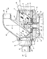
- a screen basket 1 is provided which is rotationally symmetrical with respect to an axis 2, the wall 3 of which is designed in the form of a shell in the manner of a parabolic mirror.
- a circular bottom plate 4 is located in a cup-like bottom recess of the strainer basket 1.
- the upper strainer rim is bent outwards, so that a U-shaped profiled edge results.
- the bowl-shaped strainer basket consists, for example, of a wire mesh.
- the cup-shaped bottom recess of the strainer basket 1 with the bottom plate 4 lying therein lies within a recess of a disc 5, which has several functions.
- the disc 5 carries a plurality of fan blades evenly distributed over the circumference of the strainer basket 1 gel 6 and 7, which are substantially perpendicular to the wall 3 of the strainer basket and, on their radially inner side, conform closely to the shape of the strainer wall 3 and thereby support the strainer wall.
- the outer contour 8 and 9 of the fan blades 6 and 7 is straight and has a uniform distance from the axis of rotation 2.
- the fan blade 6 extends almost over the entire height of the strainer basket 1, while the fan blade 7 extends only about half the height of the strainer basket.
- the sieve basket is driven, for example, at a speed of 3000 rpm.
- the disk 5 carrying the fan blades 6 and 7, with which the sieve basket 1 is also firmly connected also has the function of a flywheel, since when sieving powdery, free-flowing substances, such as flour, for example, during the entry of the material to be sieved can occur in the sieving machine, since the flour is often fed irregularly in practice. These shocks can also occur if the screening machine is switched on within a line that is laid between a silo and a weighing station. Due to the flywheel effect of the disc 5, the screening machine runs more smoothly, since the impacts exerted by the material to be screened on the machine are compensated for by the swinging machine. Through the sieving process, the discharge flow is evened out despite shocks when the substance to be sieved is introduced.
- the screen basket 1, the fan blades 6 and 7, the plate 4 and the disk 5 form a rotating part which is axially removable on a motor shaft 10 of an electric motor 11.
- the rotationally fixed connection between the motor shaft and the disk 5 is established by drivers 28 arranged on the motor shaft 10 and engaging in recesses in the disk 5.
- the disc 5 has a hub 12 through which the motor shaft 10 passes.
- the hub 12 is provided with indentations 13 and thus serves as a handle for removing the rotary part formed from the components 1, 4, 5, 6, 7 and 12, which can be removed from the motor shaft 10 for replacing or cleaning the strainer basket.
- the aforementioned drivable and rotatable rotating part lies within a housing 14 which is interlocked with a housing of the electric motor 11.
- the housing 14 can be closed with a housing cover 14 ', which in a manner not shown on a support arm 15 of the housing 14 is pivoted. In the position shown, the housing cover 14 ⁇ is closed and thus seals the housing from the outside.
- a feed line 16 leads into the interior of the housing and a discharge line 17 leads away from the interior of the housing.
- the feed line 16 has a line section 18 leading into the vicinity of the wall 3 of the strainer basket 1, which line section is designed as a corresponding cavity in the cover 14 ⁇ .
- This line section 18 has a mouth 19 which is adapted to the shape of the wall 3 of the screen basket along its entire circumference.
- the mouth 19 has the same distance or gap 27 to the wall 3 of the strainer 1 over its entire circumference. From the illustration it can be seen that this gap is only relatively small.
- the material to be screened enters the inside of the screen basket 1 in the direction of the arrows 20 and 21.
- the housing cover 14 ⁇ has a stop 22 for a hold-down 24 seated on a shoulder 23 of the motor shaft 10, which is made of a low-friction material, such as a polyamide. On this hold-down 24, the neck 22 of the housing cover 14 ⁇ is supported in its closed position and thus holds the hub 12, the disc 5 formed in one piece therewith and ultimately the strainer basket in the working position shown.
- the fan blades 6 and 7, which are also attached to the disk 5, are rotated at the same speed as the screen basket, so that within the housing 14, 14 ⁇ a conveying air flow in the direction of the arrow 20, 21 ⁇ and 25 is generated.
- the outlet mouth 19 of the line section and the inlet mouth 26 of the discharge line 17 lie opposite one another, separated by the wall 3 of the strainer basket located therebetween.
- the mouth 19 of the line section 18 can be expanded in the shape of a trumpet, in the exemplary embodiment shown in the horizontal plane, that is to say at right angles to the plane of the drawing sheet.
- the mouth 19 of the line section 18 can be adjustable in the longitudinal direction of the line section in order to be able to set the gap 27 between the mouth 19 and the wall 3 of the strainer basket.
- the strainer basket 1 can also have a cylindrical or conical outer surface.
- the material to be sieved for example flour, exits the feed line 16 and 18 at the mouth 19.
- the flour flow immediately hits the wall 3 of the very quickly rotating screen basket 1.
- the fan blades 6 and 7 on the screen basket produce an air flow inside the housing 14, 14, through which the material to be screened passes through the wall 3 of the screen basket and is promoted to the inlet mouth 26 of the discharge line 17.
- the substance that strikes the sieve wall 3 of the sieve basket 1 is thus immediately moved through the sieve so that the sieve basket is no longer filled with the material to be sieved.
- the sieve basket therefore does not have to constantly rotate an amount of material to be sieved.
- the volume of the strainer basket 1 can be kept very small despite the large material throughput.
- the screen basket 1 can easily be completely freed of the material to be screened, so that the machine can be quickly converted to another material. There is therefore no mixing of different substances.
- the quick and complete emptying of the strainer basket and the interior of the housing is also promoted by the blowers 5 to 7 provided in the interior of the housing.
- the screening machine explained can be switched on within a delivery line which works with compressed air and which is located between a silo and a processing station for the screened material. In this case, the material to be screened is conveyed by the compressed air mentioned in the feed line 16.
- the blowers 5 to 7 present in the interior of the housing of the sieving machine then represent an additional blower in the above-mentioned delivery line.
- the sieving machine explained can also be used as an independent machine unit, the substance to be sieved then entering the feed line 16 without pressure, so to speak. The material is then transported through the screening machine by the blowers 5 to 7 located inside the housing.
- the contour of the mouth 19 is convex in the vertical plane shown.
- the contour of the mouth 19 is also convexly curved in the non-visible horizontal plane. If a cylindrical or conical strainer basket is used, then the contour of the mouth 19 is only convexly curved in the horizontal plane (not shown), corresponding to the radius of the cylindrical strainer basket or to the radii of the conical strainer basket.
- the fabric to be screened is fed to the inside of the screen basket 1, and the screened fabric is discharged on the outside of the screen basket.
- the conveying direction of the material to be screened could also take place in the opposite direction, i.e. the material to be sieved could also be fed to the outside of the sieve basket, after which the material is then removed from the inside of the sieve basket after sieving.
- the mouth of the feed line would be concave in the bowl-shaped strainer basket shown, so it is then again adapted to the outer surface 3 of the strainer basket 1 so that the mouth contour of the feed line is at the same distance from the strainer wall 3 over its entire circumference.
- the fan blades 6 and 7 would then be arranged with a different shape on the inside of the strainer basket.
Landscapes
- Chemical & Material Sciences (AREA)
- Chemical Kinetics & Catalysis (AREA)
- Combined Means For Separation Of Solids (AREA)
- Cyclones (AREA)
Abstract
Description
- Die Erfindung bezieht sich auf eine Siebmaschine für pulverförmige, rieselfähige Stoffe, mit einem in einem Gehäuse antreibbar und drehbar gelagerten Siebkorb, dem der zu siebende Stoff über eine am Gehäuse angeordnete Zuführleitung zuführbar ist und mit einer am Gehäuse angeordneten Abführleitung für den gesiebten Stoff.
- Bei einer bekannten Siebmaschine dieser Art liegt die Drehachse des Siebkorbes horizontal. Der Siebkorb ist hierbei als Zylindertrommel ausgebildet, an dessen einer Stirnseite der zu siebende Stoff, wie z.B. Mehl, zusammen mit Förderluft eingeführt wird. Die Austragstelle des gesiebten Stoffes liegt radial an der Mantelfläche der Zylindertrommel, und zwar unterhalb der horizontal liegenden Zylindertrommel. Im Inneren der Siebtrommel befinden sich relativ zur Siebwandung bewegte, in bezug auf die Längsachse der Siebtrommel spiralförmig ausgebildete Räumleisten, die den in die Siebtrommel eingebrachten Stoff, welcher sich aufgrund der Zentrifugalkraft an die Siebwandung anlegt, auflockern, um eine Verstopfung der Siebwandung, bedingt durch Brückenbildung, zu vermeiden. Diese bekannte Siebmaschine weist mehrere Nachteile auf. Der liegende Siebkorb nimmt den zu siebenden Stoff im Inneren auf und rotiert zusammen mit dieser Stoffmenge. Bei einem erwünschten hohen Durchsatz befindet sich eine große Stoffmenge innerhalb des Siebkorbes. Für den Antrieb dieser beträchtlichen Massen muß eine hohe Motorleistung installiert werden. Diese Antriebsleistung ist deshalb auch sehr hoch, weil die Räumleisten, die zur Auflockerung des durch Fliehkraft am Siebmantel anliegenden Stoffes dienen, bei dieser Räumarbeit eine hohe Antriebsleistung erfordern. Bei diesem Räumvorgang ist ein hoher Reibeffekt unvermeidbar, was nicht nur die Antriebsleistung erhöht, sondern auch zu einer Erwärmung des zu siebenden Stoffes führt. Dies ist insbesondere bei Mehl unerwünscht. Weiterhin wird durch diesen Reibeffekt eine Zerkleinerung der abzutrennenden Teile bewirkt, was insbesondere bei schädlichen Beimengungen unerwünscht ist. Weiterhin erfordert eine solche Siebmaschine mit großvolumigem Siebkorb und starkem Antriebsmotor einen beträchtlichen Platzbedarf, da die Siebmaschine groß und entsprechend schwer baut. Da der zu siebende Stoff mittels Förderluft durch die Siebmaschine hindurchgefördert wird, stellt der eine verhältnismäßig große Stoffmenge enthaltende Siebkorb eine beträchtliche Drossel in diesem Fördersystem dar. Dies bedeutet also einen erheblichen Druckabfall im Fördersystem, so daß ein entsprechend starkes Gebläse installiert werden muß. Da, wie schon erwähnt, der liegende Siebkorb eine beträchtliche Menge an zu siebendem Stoff enthält, ist ein Umstellen der Siebmaschine auf einen anderen zu siebenden Stoff (z.B. Übergang von der einen Mehlsorte auf eine andere Mehlsorte) mit Schwierigkeiten verbunden, denn der Siebkorb muß zuerst von seiner von ihm getragenen beträchtlichen Stoffmenge vollständig entleert werden. Es hat sich hierbei gezeigt, daß ein großvolumiger Siebkorb, aus dem nahezu aller zu siebender Stoff ausgetragen worden ist, von einer gewissen Restmenge praktisch nicht befreit werden kann, da die große bereits freie Siebfläche des Siebkorbes die Förderluft hindurchläßt, ohne die in den Ecken des Siebkorbes noch lagernden Restmengen an Stoff mitzunehmen. Ein gewünschtes vollständiges Entleeren eines solchen Siebkorbes bereitet jedenfalls größte Mühe.
- Aufgabe der Erfindung ist es, eine Siebmaschine der eingangs erläuterten Art so auszugestalten, daß der Siebvorgang bei geringer Baugröße, kleiner Motorleistung, äußerst geringer Restmenge nach Abschluß des Siebvorganges, bei schonender Behandlung des zu siebenden Stoffes, also ohne mechanische Einwirkung und Erwärmung durchgeführt werden kann, wobei obendrein auch noch die Möglichkeit bestehen soll, den Förderstrom, der den zu siebenden Stoff trägt zu unterstützen, bzw. den Siebvorgang auch ohne Förderluft durchführen zu können.
- Diese Aufgabe wird bei einer Siebmaschine nach dem Oberbegriff des Anspruchs 1 erfindungsgemäß dadurch gelöst, daß die Zuführleitung einen bis auf einen Spalt an die Wand des Siebkorbes heranreichenden Leitungsabschnitt aufweist, und daß der Siebkorb an der dem zuführenden Leitungsabschnitt abgewandten Wandseite mit Gebläseflügeln versehen ist.
- Aufgrund dieser Ausgestaltung wird ein Auffüllen des Siebkorbes mit dem zu siebenden Stoff vermieden, weil er immer im wesentlichen gegen eine gereinigte Siebfläche fällt, die der Austrittsfläche der Mündung des Leitungsabschnittes entspricht, der bis auf einen geringen Spalt bis an die Siebwandung heranreicht. Im Siebkorb verbleiben dann nur noch diejenigen Anteile des zu siebendne Stoffes, die größer als die Siebmaschenweite sind. Der Spalt muß also so groß sein, daß die zu erwartenden abzusondernden Teile zwischen der Mündung des Leitungsabschnittes und der Siebwand hindurchtreten können. Je nach Beladung des angeförderten Stoffstromes wird es dann eine Zeit dauern, bis der Siebkorb von diesen groben Teilen befreit werden muß. Es wird aber eine Auffüllung des Siebkorbes mit dem durch das Sieb hindurchtretenden Stoffes vermieden, wodurch die eingangs erläuterten Nachteile, nämlich eine hohe Antriebsleistung, vermieden wird. Da die wirksame Siebfläche jeweils auf den Flächenbereich begrenzt ist, der der Mündungsfläche des Leitungsabschnittes entspricht und der Siebkorb nur die auszusiebenden Teile aufnimmt, kommt man mit einem kleinen Siebkorb und damit mit einer kleinen Siebmaschine aus, die einen geringen Platzbedarf neben der schon erwähnten geringen Antriebsleistung erfordert. Die Antriebsleistung ist auch deshalb so gering, weil die bei der bekannten Maschine sich aufbauende Stoffschicht, welche durch die Räumleisten aufgelockert wurde, entfällt. Dies ist der wesentliche Grund für eine schonende Behandlung des zu siebenden Stoffes, da die mechanische Einwirkung und die damit zusammenhängende Erwärmung entfällt. Durch die Anordnung von Gebläseflügeln wird der Förderstrom, d.h. der Luftstrom, der zur Förderung des zu siebenden Stoffes dient, unterstützt. Da die Gebläseflügel auf derjenigen Wandweite des Siebkorbes angeordnet sind, die der Mündung des Leitungsabschnittes gegenüberliegt, wird durch die rotierenden Gebläseflügel ein Luftstrom erzeugt, der den durch das Sieb hindurchgetretenen Stoff weiterfördert, wodurch nicht nur eine Unterstützung des Förderstromes eintritt, sondern sogar die Möglichkeit besteht, den zu siebenden Stoff ohne Förderluftstrom in den Siebkorb einzubringen und zu sieben. Somit werden alle Einzelziele der eingangs angegebenen Aufgabe erreicht.
- Gemäß weiteren vorteilhaften Ausgestaltungen der Erfindung kann der Leitungsabschnitt mit seiner Mündung sowohl im Inneren des Siebkorbes als auch an der Außenseite des Siebkorbes liegen, wobei die Gebläseflügel jeweils entsprechenden der grundsätzlichen Angabe im Anspruch 1 an der dem Leitungsabschnitt abgewandten Wandseite des Siebkorbes vorgesehen sind, d.h. bei Anordnung der Mündung im Inneren des Siebkorbes liegen die Gebläseflügel an der Außenwandung und bei Anordnung der Mündung an der Außenwand liegen die Gebläseflügel an der Innenwand des Siebkorbes.
- Eine besonders einfache konstruktive Ausgestaltung ergibt sich durch die Maßnahme nach Anspruch 4 und 5, weil hierdurch der Siebkorb nicht nur in einfacher Weise auswechselbar oder zu Reinigungszwecken entnehmbar ist, sondern die Antriebsverbindung ist trotz leichter Lösbarkeit des Siebkorbes von der Antriebswelle einfach gestaltet und der Siebkorb in einfacher Weise während des Betriebes in seiner Betriebslage gehalten.
- Entsprechend einer weiteren vorteilhaften Ausgestaltung der Erfindung ist es möglich, daß sich nur einige der Gebläseflügel über die gesamte Höhe des Siebkorbes erstrecken. Dies hängt von der benötigen Förderleistung für den bereits durch das Sieb durchgetretenen Stoff ab.
- Selbstverständlich können auch alle Gebläseflügel sich über die gesamte Höhe des Siebkorbes erstrecken.
- Eine vorteilhafte Ausgestaltung, die einen geringen Platzbedarf verursacht, ergibt sich dadurch, daß der Siebkorb schalenförmig nach Art eines Parabolspiegels, konisch oder zylinderförmig ausgebildet ist.
- In vorteilhafter Ausgestaltung der Erfindung weisen die Gebläseflügel einen Abstand zur Wand des Siebkorbes auf. Hierdurch wird ein Stau des durch das Sieb hindurchtretenden Stoffes an den Anlageflächen verhindert.
- Wenn dagegen die Gebläseflügel sehr schmal ausgebildet werden, so kann es in Abhängigkeit von dem zu siebenden Stoff unter Umständen auch möglich sein, daß die Gebläseflügel an der Wand des Siebkorbes anliegen. Hierdurch dienen sie gleichzeitig als Stütze für das Sieb, wodurch weitere Maßnahmen zur Erhöhung der Steifigkeit des Siebes vermieden sind.
- Die Ausgestaltung nach Anspruch 9 ist eine vorteilhafte Voraussetzung dafür, daß der Spalt zwischen der Mündung und der Siebkorbwand am gesamten Umfang der Mündung gleich groß ist.
- Eine geringfügige Abweichung von dieser Anpassung führt zu einer weiteren vorteilhaften Ausgestaltung, die darin besteht, daß die Mündung des Leitungsabschnittes längs Ihres Umfanges einen unterschiedlich großen Spalt zur Wand des Siebkorbes aufweist, derart, daß der gegen die Drehrichtung des Siebkorbes am weitesten hervorragende Wandbereich der Mündung den geringsten Spalt zur Wand des Siebkorbes aufweist, der sich zu dem gegenüberliegenden in Drehrichtung am weitesten hervorragenden Wandbereich der Mündung stetig vergrößert. Hierdurch wird erreicht, daß jeder Siebabschnitt, der aufgrund der Drehung des Siebkorbes an die Mündung des Leitungsabschnittes herangeführt wird, einen geringeren Spalt zum Leitungsabschnitt vorfindet, als in dem Bereich, den er aufgrund der Drehung des Siebkorbes verläßt und welcher dem erstgenannten Bereich in Drehrichtung betrachtet, gegenüberliegt. Hierdurch ist es möglich, den gegen die Drehrichtung am weitesten herausragenden Bereich des Leitungsabschnittes sehr eng an die Wandung des Siebkorbes heranzuführen und zwar kann der Spalt so eng gemacht werden, daß bereits ausgesiebte grobe Teile nicht mehr in den Mündungsbereich eintreten können, während an der gegenüberliegenden Seite des Leitungsabschnittes die durch die Siebwandung aufgefangenen groben Teile aufgrund des erweiterten Spaltes aus dem Mündungsbereich austreten. Hierdurch wird also vermieden, daß bereits ausgeschiedene Grobteile wieder in den aktiven Siebbereich gelangen, in welchem sie die Siebleistung verminden würden.
- Damit die Siebmaschine unterschiedlichen Korngrößen des zu siebenden Stoffes anpaßbar ist, ist in weiterer vorteilhafter Ausgestaltung der Erfindung der Leitungsabschnitt zur Einstellung des Spaltes zwischen der Mündung und dem Siebkorb längsverstellbar.
- Zur Vergrößerung der aktiven Siebfläche kann in vorteihafter Weise die Mündung des Leitungsabschnittes trompetenförmig erweitert sein.
- Eine besonders günstige Wirkung im Hinblick auf die Förderung des zu siebenden Stoffes ergibt sich gemäß einer vorteilhaften Ausbildung der Erfindung dadurch, daß die Austrittsmündung des Leitungsabschnittes und die Eintrittsmündung der Abführleitung getrennt durch die dazwischenliegenden Siebkorbwandung einander gegenüberliegen. Hierdurch gelangt der durch das Sieb hindurchtretende Stoff unmittelbar in die Abführleitung, wodurch Reibungsverluste des zu fördernden Stoffes innerhalb der Siebmaschine, d.h. innerhalb des den Siebkorb umgebenden Gehäuses vermieden werden.
- Die erfindungsgemäße Siebmaschine eignet sich insbesondere zum Sieben von Mehl, da die erforderliche schonende Behandlung gewährleistet ist. Aufgrund der geringen Abmessungen ist es möglich, die erfindungsgemäße Siebmaschine in eine Förderleitung zwischen Silo und Verbraucher bzw. Verwiegestation einzusetzen, so daß in der Backstube stets gesiebtes Mehl angefördert wird, was den bisher üblichen Siebvorgang nach dem Fördern des Mehles überflüssig macht.
- Der Einbau der erfindungsgemäßen Siebmaschine in einer Förderleitung wird nicht nur aufgrund der geringen Abmessungen ermöglicht, sondern dieser Einbau wird auch dadurch erleichtert, daß die Siebmaschine keine bevorzugte Einbaulage aufweist, d.h. der Siebkorb kann um eine Achse rotieren, die jeden beliebigen Winkel einnimmt.
- Die Erfindung wird nachfolgend anhand eines in der Zeichnung dargestellten Ausführungsbeispieles näher erläutert. Die einzige Figur dieser Zeichnung zeigt einen teilweisen Längsschnitt durch eine Siebmaschine.
- Wie aus der Zeichnung ersichtlich ist ein zu einer Achse 2 rotationssymmetrisch ausgebildeter Siebkorb 1 vorgesehen, dessen Wand 3 schalenförmig nach Art eines Parabolspiegels ausgebildet ist. In einer napfartigen Bodenvertiefung des Siebkorbes 1 befindet sich eine kreisförmige Bodenplatte 4. Der obere Siebkorbrand ist nach außen abgebogen, so daß sich ein U-förmig profilierter Rand ergibt. Der schalenförmige Siebkorb besteht beispielsweise aus einem Drahtgeflecht. Die napfförmgie Bodenvertiefung des Siebkorbes 1 mit der darin liegenden Bodenplatte 4 liegt innerhalb einer Vertiefung einer Scheibe 5, die mehrere Funktionen hat. Die Scheibe 5 trägt mehrere über den Umfang des Siebkorbes 1 gleichmäßig verteilte Gebläseflü gel 6 und 7, die im wesentlichen senkrecht zur Wand 3 des Siebkorbes stehen und an ihrer radial innen liegenden Seite der Form der Siebwand 3 angepaßt eng an dieser anliegen und die Siebwand dadurch abstützen. Die Außenkontur 8 und 9 der Gebläseflügel 6 und 7 ist geradlinig und weist einen gleichmäßigen Abstand zur Rotationsachse 2 auf. Die Gebläseflügel 6 und 7, die aus Blech, Leichtmetallguß oder Kunststoff bestehen können, haben eine geringe Dicke, wodurch nur ein äußerst geringer Teil der Siebfläche abgedeckt wird. Da die Gebläseflügel gleichzeitig Stützfunktion für den Siebkorb haben, ist ein zusätzliches Stützgeflecht entbehrlich. In der Zeichnung sind unterschiedlich große Gebläseflügel 6 und 7 dargestellt. Der Gebläseflügel 6 erstreckt sich nahezu über die gesamte Höhe des Siebkorbes 1, während sich der Gebläseflügel 7 nur etwa über die halbe Höhe des Siebkorbes erstreckt. Es können z.B. vier Gebläseflügel 6 und acht Gebläseflügel 7 vorhanden sein, die abwechselnd über den gesamten Umfang des Siebkorbes gleichmäßg verteilt angeordnet sind. Da die Gebläseflügel 6 und 7 eine Stützwirkung auf den Siebkorb 1 ausüben, kann dieser aus einem sehr feinen Gewebe hergestellt sein, ohne daß eine Verformung des Siebkorbes bei hohen Umdrehungszahlen aufgrund der auftretenden Fliehkräfte eintreten würde. Bei der Verwendung der Siebmaschine zum Sieben von Mehl wird der Siebkorb beispielsweise mit einer Drehzahl von 3000 U/min angetrieben. Die die Gebläseflügel 6 und 7 tragende Scheibe 5, mit der auch der Siebkorb 1 fest verbunden ist, hat aber auch noch die Funktion einer Schwungmasse, da beim Sieben von pulverförmigen, rieselförmigen Stoffen, wie z.B. Mehl, beim Eintrag des zu siebenden Stoffes in die Siebmaschine Stöße auftreten können, da das Mehl in der Praxis oft unregelmäßig zugeführt wird. Diese Stöße können auch dann auftreten, wenn die Siebmaschine innerhalb einer Leitung eingeschaltet ist, die zwischen einem Silo und einer Verwiegestation verlegt ist. Durch die Schwungradwirkung der Scheibe 5 läuft die Siebmaschine ruhiger, da die von dem zu siebenden Stoff auf die Maschine ausgeübten Stöße durch die Schwungmaschine kompensiert werden. Durch den Siebvorgang wird trotz Stöße beim Eintrag des zu siebenden Stoffes der Austragsstrom vergleichmäßigt.
- Der Siebkorb 1, die Gebläseflügel 6 und 7, die Platte 4 und die Scheibe 5 bilden ein Drehteil, das axial abziehbar auf einer Motorwelle 10 eines Elektromotors 11 sitzt. Durch auf der Motorwelle 10 angeordnete Mitnehmer 28, die in Ausnehmungen der Scheibe 5 eingreifen, wird die drehfeste Verbindung zwischen der Motorwelle und der Scheibe 5 hergestellt. Die Scheibe 5 weist eine Nabe 12 auf, durch die die Motorwelle 10 hindurchfaßt. Die Nabe 12 ist mit Einbuchtungen 13 versehen und dient somit als Handhabe zum Abziehen des aus den Bauteilen 1, 4, 5, 6, 7 und 12 gebildeten Drehteils, das zum Auswechseln oder Reinigen des Siebkorbes von der Motorwelle 10 abgezogen werden kann.
- Das vorerwähnte antreibbare und drehbare Drehteil liegt innerhalb eines Gehäuses 14, das mit einem Gehäuse des Elektromotors 11 verblockt ist. Das Gehäuse 14 ist mit einem Gehäusedeckel 14ʹ verschließbar, der in nicht dargestellter Weise an einem Tragarm 15 des Gehäuse 14 schwenkbar angelenkt ist. In der dargestellten Stellung ist der Gehäusedeckel 14ʹ geschlossen und dichtet somit das Gehäuse nach außen ab. Ins Gehäuseinnere führt eine Zuführleitung 16 und aus dem Gehäuseinneren führt eine Abführleitung 17 weg.
- Die Zuführleitung 16 hat einen bis in die Nähe der Wandung 3 des Siebkorbes 1 führenden Leitungsabschnitt 18, der als entsprechender Hohlraum im Deckel 14ʹ ausgebildet ist. Dieser Leitungsabschnitt 18 hat eine Mündung 19, die der Form der Wandung 3 des Siebkorbes längs ihres gesamten Umfanges angepaßt ist. Hierbei weist die Mündung 19 an ihrem gesamten Umfang den gleichen Abstand bzw. Spalt 27 zur Wandung 3 des Siebkorbes 1 auf. Aus der Darstellung ist ersichtlich, daß dieser Spalt nur verhältnismäßig gering ist. Der zu siebende Stoff tritt in Richtung der Pfeile 20 und 21 ins Innere des Siebkorbes 1 ein. Der Gehäusedeckel 14ʹ hat einen Anschlag 22 für einen auf einem Ansatz 23 der Motorwelle 10 sitzenden Niederhalter 24, der aus einem reibungsarmen Material, wie z.B. einem Polyamid, besteht. Auf diesem Niederhalter 24 stützt sich der Ansatz 22 des Gehäusedeckels 14ʹ in seiner geschlossenen Lage ab und hält somit die Nabe 12, die damit einstückig ausgebildete Scheibe 5 und letzlich den Siebkorb in der dargestellten Arbeitslage.
- Beim Antrieb des Siebkorbes 1 werden die ebenfalls auf der Scheibe 5 befestigten Gebläseflügel 6 und 7 mit gleicher Drehzahl wie der Siebkorb gedreht, so daß innerhalb des Gehäuses 14, 14ʹ ein Förderluftstrom in der Pfeilrichtung 20, 21ʹ und 25 erzeugt wird. Im dargestellten Ausführungsbeispiel liegen die Austrittsmündung 19 des Leitungsabschnittes und die Eintrittsmündung 26 der Abführleitung 17 getrennt durch die dazwischenliegende Wand 3 des Siebkorbes einander gegenüber. Die Mündung 19 des Leitungsabschnittes 18 kann trompetenförmig erweitert sein, und zwar beim dargestellten Ausführungsbeispiel in der Horizontalebene, also rechtwinklig zur Zeichenblattebene. Obwohl aus der zeichnerischen Darstellung des Ausführungsbeispieles nicht ersichtlich, kann die Mündung 19 des Leitungsabschnittes 18 in Längsrichtung des Leitungsabschnittes verstellbar sein, um den Spalt 27 zwischen der Mündung 19 und der Wandung 3 des Siebkorbes einstellen zu können. Der Siebkorb 1 kann außer der dargestellten schalenartigen Form auch eine zylindrische oder konische Mantelfläche haben.
- Die Arbeitsweise der dargestellten Siebmaschine ist folgende:
- Der zu siebende Stoff, z.B. Mehl, tritt an der Mündung 19 aus der Zuführleitung 16 und 18 aus. Der Mehlstrom trifft hierauf sofort auf die Wandung 3 des sehr schnell drehenden Siebkorbes 1. Durch die am Siebkorb vorhandenen Gebläseflügel 6 und 7 wird eine Luftstrom im Inneren des Gehäuses 14, 14ʹ erzeugt, durch den der zu siebende Stoff durch die Wandung 3 des Siebkorbes und zur Eintrittsmündung 26 der Abführleitung 17 gefördert wird. Der auf die Siebwandung 3 des Siebkorbes 1 auftreffende Stoff wird also sofort durch das Sieb hindurchbewegt, so daß also nicht mehr der Siebkorb mit dem zu siebenden Stoff angefüllt wird. Der Siebkorb muß somit keine zu siebende Stoffmenge ständig in Drehung versetzen. Das Volumen des Siebkorbes 1 kann trotz großem Stoffdurchsatz sehr klein gehalten werden. Der Siebkorb 1 kann leicht vollständig vom zu siebenden Stoff befreit werden, so daß also die Maschine schnell auf einen anderen Stoff umrüstbar ist. Es tritt somit kein Vermischen von verschiedenartigen Stoffen ein. Das schnelle und vollständige Entleeren des Siebkorbes und des Gehäuseinneren wird auch durch das im Gehäuseinneren vorhanden Gebläse 5 bis 7 begünstigt. Wie schon erwähnt, kann die erläuterte Siebmaschine innerhalb einer mit Druckluft arbeitenden Förderleitung eingeschaltet sein, die sich zwischen einem Silo und einer Verarbeitungsstation für den gesiebten Stoff befindet. In diesem Fall wird also der zu siebende Stoff durch die erwähnte Druckluft in der Zuführleitung 16 gefördert. Das im Inneren des Gehäuses der Siebmaschine vorhandene Gebläse 5 bis 7 stellt dann also ein zusätzliches Gebläse in der erwähnten Förderleitung dar. Die erläuterte Siebmaschine kann aber auch als selbständige Maschineneinheit verwendet werden, wobei dann der zu siebende Stoff sozusagen drucklos bei der Zufuhrleitung 16 eintritt. Durch das im Gehäuseinneren befindliche Gebläse 5 bis 7 wird dann der Stoff durch die Siebmaschine transportiert.
- Beim dargestellten Ausführungsbeispiel mit einem schalenförmigen Siebkorb 1 ist die Kontur der Mündung 19 in der dargestellten Vertikalebene konvex gewölbt.
- Auch in der nicht sichtbaren Horizontalebene ist die Kontur der Mündung 19 konvex gewölbt. Wenn ein zylindrischer oder konischer Siebkorb verwendet wird, dann ist die Kontur der Mündung 19 lediglich in der nicht gezeigten Horizontalebene konvex gewölbt, entsprechend dem Radius des zylindrischen Siebkorbes, bzw. entsprechend den Radien des konischen Siebkorbes.
- Bei dem dargestellten Ausführungsbeispiel wird der zu siebende Stoff dem Inneren des Siebkorbes 1 zugeführt, und der Austrag des gesiebten Stoffes erfolgt an der Außenseite des Siebkorbes. Bei einem anderen Ausführungsbeispiel könnte die Förderrichtung des zu siebenden Stoffes auch in umgekehrter Richtung erfolgen, d.h. der zu siebende Stoff könnte auch von außen her der Siebkorbwandung zugeleitet werden, worauf dann nach dem Sieben der Stoff vom Inneren des Siebkorbes her weggeführt wird. In diesem Fall würde dann die Mündung der Zuführleitung beim dargestellten schalenförmigen Siebkorb konkav verlaufen, ist dann also wieder der Mantelfläche 3 des Siebkorbes 1 so angepaßt, daß die Mündungskontur der Zuführleitung über ihren gesamten Umfang gleichen Abstand von der Siebkorbwandung 3 hat. In diesem Fall würde man dann die Gebläseflügel 6 und 7 mit einer anderen Formgebung an der Innenseite des Siebkorbes anordnen.
Claims (15)
Priority Applications (1)
| Application Number | Priority Date | Filing Date | Title |
|---|---|---|---|
| AT87107326T ATE45517T1 (de) | 1986-05-20 | 1987-05-20 | Siebmaschine fuer pulverfoermige, rieselfaehige stoffe. |
Applications Claiming Priority (2)
| Application Number | Priority Date | Filing Date | Title |
|---|---|---|---|
| CH2028/86 | 1986-05-20 | ||
| CH2028/86A CH665967A5 (de) | 1986-05-20 | 1986-05-20 | Siebmaschine fuer pulverfoermige, rieselfaehige stoffe. |
Publications (2)
| Publication Number | Publication Date |
|---|---|
| EP0246629A1 true EP0246629A1 (de) | 1987-11-25 |
| EP0246629B1 EP0246629B1 (de) | 1989-08-16 |
Family
ID=4224231
Family Applications (1)
| Application Number | Title | Priority Date | Filing Date |
|---|---|---|---|
| EP87107326A Expired EP0246629B1 (de) | 1986-05-20 | 1987-05-20 | Siebmaschine für pulverförmige, rieselfähige Stoffe |
Country Status (4)
| Country | Link |
|---|---|
| EP (1) | EP0246629B1 (de) |
| AT (1) | ATE45517T1 (de) |
| CH (1) | CH665967A5 (de) |
| DE (1) | DE3760441D1 (de) |
Cited By (1)
| Publication number | Priority date | Publication date | Assignee | Title |
|---|---|---|---|---|
| WO2020194169A1 (en) * | 2019-03-22 | 2020-10-01 | Flsmidth A/S | Centrifugal separator and screen having blades for same |
Citations (3)
| Publication number | Priority date | Publication date | Assignee | Title |
|---|---|---|---|---|
| DE56224C (de) * | e. DE FAUCOM-PRE in Paris, 95 Boulevard de Beaumnrchais | Sichtemaschine | ||
| GB1361712A (en) * | 1972-04-06 | 1974-07-30 | Advanced Prod Eng Corp | Filtration apparatus |
| US3837483A (en) * | 1973-03-22 | 1974-09-24 | H Noll | Sifters for grain and chemical industries |
-
1986
- 1986-05-20 CH CH2028/86A patent/CH665967A5/de not_active IP Right Cessation
-
1987
- 1987-05-20 EP EP87107326A patent/EP0246629B1/de not_active Expired
- 1987-05-20 DE DE8787107326T patent/DE3760441D1/de not_active Expired
- 1987-05-20 AT AT87107326T patent/ATE45517T1/de not_active IP Right Cessation
Patent Citations (3)
| Publication number | Priority date | Publication date | Assignee | Title |
|---|---|---|---|---|
| DE56224C (de) * | e. DE FAUCOM-PRE in Paris, 95 Boulevard de Beaumnrchais | Sichtemaschine | ||
| GB1361712A (en) * | 1972-04-06 | 1974-07-30 | Advanced Prod Eng Corp | Filtration apparatus |
| US3837483A (en) * | 1973-03-22 | 1974-09-24 | H Noll | Sifters for grain and chemical industries |
Cited By (1)
| Publication number | Priority date | Publication date | Assignee | Title |
|---|---|---|---|---|
| WO2020194169A1 (en) * | 2019-03-22 | 2020-10-01 | Flsmidth A/S | Centrifugal separator and screen having blades for same |
Also Published As
| Publication number | Publication date |
|---|---|
| CH665967A5 (de) | 1988-06-30 |
| ATE45517T1 (de) | 1989-09-15 |
| DE3760441D1 (en) | 1989-09-21 |
| EP0246629B1 (de) | 1989-08-16 |
Similar Documents
| Publication | Publication Date | Title |
|---|---|---|
| DE2462568C2 (de) | Mähdrescher | |
| DE2000605B2 (de) | 24.11.69 V.St.vAmerika 879214 Mähdrescher in Axialflußbauart Sperry Rand Corp, New Holland, Pa. (V.StA.) | |
| DE2943839A1 (de) | Maehdrescher mit axialer durchlaufrichtung | |
| DE2150800A1 (de) | Vorrichtung zum Sieben von Saatgut u.dgl. | |
| EP2428109B1 (de) | Abscheideaggregat für einen Mähdrescher | |
| DE2626815C3 (de) | Axialdreschmaschine eines Mähdreschers | |
| DE4438841C2 (de) | Pumpe mit einer Schneideinrichtung | |
| DD291001A5 (de) | Verfahren und vorrichtung zur aufarbeitung von restteig zu neuteig | |
| DE3038794C2 (de) | Rührwerksmühle | |
| DE3617495C2 (de) | Fördervorrichtung insbesondere für steife Massen | |
| DE3324492C2 (de) | Vorrichtung zum Trennen eines Korn-Spreu-Gemisches | |
| DE3140624A1 (en) | Dried material pulverizing and discharging device for multistage continuous vacuum drying apparatus | |
| DE2434685A1 (de) | Verfahren und vorrichtung zum entfernen des fleisches von den knochen ganzer oder zerteilter geschlachteter tiere, beispielsweise gefluegel | |
| DE4425906C2 (de) | Naßmahlsystem | |
| DE102019205147A1 (de) | Verfahren zur Entleerung einer Vorrichtung zur Herstellung von Granulaten oder Extrudaten | |
| EP0246629B1 (de) | Siebmaschine für pulverförmige, rieselfähige Stoffe | |
| DE3313517A1 (de) | Granulator | |
| DE3037332C2 (de) | Mischer für Schüttgut und Suspensionen, insbesondere faserige Suspensionen | |
| DE3542671A1 (de) | Vorrichtung zur feinstzerkleinerung, emulgierung und weiterverarbeitung von fleisch oder dergleichen unter vakuum | |
| WO1988004577A1 (fr) | Procede et dispositif du type broyeur permettant sa mise en oeuvre pour le traitement de produits de subsistance | |
| EP0614700B1 (de) | Auswerfer für Schneidmischer | |
| EP1606055B1 (de) | Einrichtung zum trennen und abfördern von rohstoffen | |
| EP0884105A1 (de) | Einzugs-, Stütz-, Lager- und Haltevorrichtung für Zerkleinerungsmaschinen | |
| DE102022112948B3 (de) | Zellenradschleuse und Prozessanlage mit einer Zellenradschleuse | |
| DE2938950A1 (de) | Klassiersieb und entleerungsvorrichtung hierfuer |
Legal Events
| Date | Code | Title | Description |
|---|---|---|---|
| PUAI | Public reference made under article 153(3) epc to a published international application that has entered the european phase |
Free format text: ORIGINAL CODE: 0009012 |
|
| 17P | Request for examination filed |
Effective date: 19870928 |
|
| AK | Designated contracting states |
Kind code of ref document: A1 Designated state(s): AT CH DE FR GB IT LI LU |
|
| 17Q | First examination report despatched |
Effective date: 19880530 |
|
| GRAA | (expected) grant |
Free format text: ORIGINAL CODE: 0009210 |
|
| AK | Designated contracting states |
Kind code of ref document: B1 Designated state(s): AT CH DE FR GB IT LI LU |
|
| REF | Corresponds to: |
Ref document number: 45517 Country of ref document: AT Date of ref document: 19890915 Kind code of ref document: T |
|
| GBT | Gb: translation of ep patent filed (gb section 77(6)(a)/1977) | ||
| REF | Corresponds to: |
Ref document number: 3760441 Country of ref document: DE Date of ref document: 19890921 |
|
| ITF | It: translation for a ep patent filed | ||
| ET | Fr: translation filed | ||
| PLBE | No opposition filed within time limit |
Free format text: ORIGINAL CODE: 0009261 |
|
| STAA | Information on the status of an ep patent application or granted ep patent |
Free format text: STATUS: NO OPPOSITION FILED WITHIN TIME LIMIT |
|
| 26N | No opposition filed | ||
| ITTA | It: last paid annual fee | ||
| PGFP | Annual fee paid to national office [announced via postgrant information from national office to epo] |
Ref country code: FR Payment date: 19930406 Year of fee payment: 7 |
|
| PGFP | Annual fee paid to national office [announced via postgrant information from national office to epo] |
Ref country code: LU Payment date: 19930407 Year of fee payment: 7 |
|
| PGFP | Annual fee paid to national office [announced via postgrant information from national office to epo] |
Ref country code: CH Payment date: 19930414 Year of fee payment: 7 |
|
| PGFP | Annual fee paid to national office [announced via postgrant information from national office to epo] |
Ref country code: GB Payment date: 19930507 Year of fee payment: 7 |
|
| PGFP | Annual fee paid to national office [announced via postgrant information from national office to epo] |
Ref country code: AT Payment date: 19930531 Year of fee payment: 7 |
|
| EPTA | Lu: last paid annual fee | ||
| PG25 | Lapsed in a contracting state [announced via postgrant information from national office to epo] |
Ref country code: LU Free format text: LAPSE BECAUSE OF NON-PAYMENT OF DUE FEES Effective date: 19940520 Ref country code: GB Effective date: 19940520 Ref country code: AT Effective date: 19940520 |
|
| PG25 | Lapsed in a contracting state [announced via postgrant information from national office to epo] |
Ref country code: LI Effective date: 19940531 Ref country code: CH Effective date: 19940531 |
|
| GBPC | Gb: european patent ceased through non-payment of renewal fee |
Effective date: 19940520 |
|
| PG25 | Lapsed in a contracting state [announced via postgrant information from national office to epo] |
Ref country code: FR Effective date: 19950131 |
|
| REG | Reference to a national code |
Ref country code: CH Ref legal event code: PL |
|
| REG | Reference to a national code |
Ref country code: FR Ref legal event code: ST |
|
| PG25 | Lapsed in a contracting state [announced via postgrant information from national office to epo] |
Ref country code: IT Free format text: LAPSE BECAUSE OF NON-PAYMENT OF DUE FEES;WARNING: LAPSES OF ITALIAN PATENTS WITH EFFECTIVE DATE BEFORE 2007 MAY HAVE OCCURRED AT ANY TIME BEFORE 2007. THE CORRECT EFFECTIVE DATE MAY BE DIFFERENT FROM THE ONE RECORDED. Effective date: 20050520 |
|
| PGFP | Annual fee paid to national office [announced via postgrant information from national office to epo] |
Ref country code: DE Payment date: 20060519 Year of fee payment: 20 |