EP0246482B1 - Pompe à palettes - Google Patents
Pompe à palettes Download PDFInfo
- Publication number
- EP0246482B1 EP0246482B1 EP87106419A EP87106419A EP0246482B1 EP 0246482 B1 EP0246482 B1 EP 0246482B1 EP 87106419 A EP87106419 A EP 87106419A EP 87106419 A EP87106419 A EP 87106419A EP 0246482 B1 EP0246482 B1 EP 0246482B1
- Authority
- EP
- European Patent Office
- Prior art keywords
- cam ring
- housing
- end plate
- rotor
- rear end
- Prior art date
- Legal status (The legal status is an assumption and is not a legal conclusion. Google has not performed a legal analysis and makes no representation as to the accuracy of the status listed.)
- Expired - Lifetime
Links
- 230000002093 peripheral effect Effects 0.000 claims description 18
- 230000010355 oscillation Effects 0.000 description 7
- 238000004519 manufacturing process Methods 0.000 description 4
- 238000005520 cutting process Methods 0.000 description 3
- 239000012530 fluid Substances 0.000 description 2
- 238000002485 combustion reaction Methods 0.000 description 1
- 230000003247 decreasing effect Effects 0.000 description 1
- 230000001419 dependent effect Effects 0.000 description 1
Images


Classifications
-
- F—MECHANICAL ENGINEERING; LIGHTING; HEATING; WEAPONS; BLASTING
- F01—MACHINES OR ENGINES IN GENERAL; ENGINE PLANTS IN GENERAL; STEAM ENGINES
- F01C—ROTARY-PISTON OR OSCILLATING-PISTON MACHINES OR ENGINES
- F01C21/00—Component parts, details or accessories not provided for in groups F01C1/00 - F01C20/00
- F01C21/10—Outer members for co-operation with rotary pistons; Casings
-
- F—MECHANICAL ENGINEERING; LIGHTING; HEATING; WEAPONS; BLASTING
- F04—POSITIVE - DISPLACEMENT MACHINES FOR LIQUIDS; PUMPS FOR LIQUIDS OR ELASTIC FLUIDS
- F04C—ROTARY-PISTON, OR OSCILLATING-PISTON, POSITIVE-DISPLACEMENT MACHINES FOR LIQUIDS; ROTARY-PISTON, OR OSCILLATING-PISTON, POSITIVE-DISPLACEMENT PUMPS
- F04C15/00—Component parts, details or accessories of machines, pumps or pumping installations, not provided for in groups F04C2/00 - F04C14/00
-
- F—MECHANICAL ENGINEERING; LIGHTING; HEATING; WEAPONS; BLASTING
- F04—POSITIVE - DISPLACEMENT MACHINES FOR LIQUIDS; PUMPS FOR LIQUIDS OR ELASTIC FLUIDS
- F04C—ROTARY-PISTON, OR OSCILLATING-PISTON, POSITIVE-DISPLACEMENT MACHINES FOR LIQUIDS; ROTARY-PISTON, OR OSCILLATING-PISTON, POSITIVE-DISPLACEMENT PUMPS
- F04C2230/00—Manufacture
- F04C2230/60—Assembly methods
- F04C2230/603—Centering; Aligning
-
- Y—GENERAL TAGGING OF NEW TECHNOLOGICAL DEVELOPMENTS; GENERAL TAGGING OF CROSS-SECTIONAL TECHNOLOGIES SPANNING OVER SEVERAL SECTIONS OF THE IPC; TECHNICAL SUBJECTS COVERED BY FORMER USPC CROSS-REFERENCE ART COLLECTIONS [XRACs] AND DIGESTS
- Y10—TECHNICAL SUBJECTS COVERED BY FORMER USPC
- Y10T—TECHNICAL SUBJECTS COVERED BY FORMER US CLASSIFICATION
- Y10T29/00—Metal working
- Y10T29/49—Method of mechanical manufacture
- Y10T29/49229—Prime mover or fluid pump making
- Y10T29/49236—Fluid pump or compressor making
- Y10T29/49245—Vane type or other rotary, e.g., fan
Definitions
- the present invention relates in general to a vane pump and in particular to a vane pump which is used in a power steering apparatus associated with a internal combustion engine.
- FIGS. 5 and 6 of the accompanying drawings A conventional vane pump as shown in FIGS. 5 and 6 of the accompanying drawings is disclosed in the US-A- 4,373,871.
- reference numeral 1 designates a housing formed with a housing bore 2.
- a drive shaft 4 In the housing bore 2 is freely rotatably supported a drive shaft 4 through a bearing 3 secured to the housing 1.
- a pump portion generally indicated by reference numeral 5 is housed in the housing bore 2 of the housing 1 and includes a cam ring 6 having a cam surface 6a consisting of a large circular portion and a small circular portion, a rotor 7 freely rotatably supported in the cam ring 6 and having a plurality of equiangularly spaced slots formed therein, a plurality of vanes 8 radially movably received in the slots of the rotor 7, and front and rear plates 9 and 10 by which the cam ring 6 is closed at its opposite ends.
- the drive shaft 4 extends through a central opening formed in the front plate 9 and through a central opening formed in the rotor 7, and the rotor 7 is engaged with the drive shaft 4 through a spline formed in the drive shaft 4 between the front and rear plate 9 and 10.
- a rear end portion of the drive shaft 4 extending rearward from the rotor 7 is freely rotatably supported on a bearing portion 11 formed in the the rear plate 10 through a bearing 12.
- the front plate 9, cam ring 6 and rear plate 10 are held together in assembled relationship by means of a pair of knock pins 14.
- Each of the knock pins 14 is inserted into a bore 13 formed in the inner surface of the housing 1, a bore 15 passing through the front plate 9, a bore 16 passing through the cam ring 6 and into a bore 17 formed in the rear plate 10 so that the center axis of the rotor 7 is consistent with the center axis of the cam surface 6a of the cam ring 6.
- the vane pump is to be operated in this offset condition because the slight offset between the center axes 6b and 7a cannot be inspected visually.
- the rotor 7 is rotated in the counter-clockwise direction indicated by an arrow B in FIG.
- the vane 8b of two adjacent vanes 8a and 8b which are located at the section between an intake port 6c and a discharge port 6d and which define a pump chamber 18, is slightly lengthened in its length from the outer surface of the rotor 7 to the cam surface 6a than the vane 8b in the condition that the center axis 7a of the rotor 7 is not offset. For this reason, the pump chamber 18 is slightly increased in its volume at the side of the vane 8b.
- the vane 8d of two adjacent vanes 8c and 8d which are located at the section between the intake port 6c and the discharge port 6d and which define a pump chamber 19 opposite to the chamber 18, is slightly shortened in its length from the outer surface of the rotor 7 to the cam surface 6a than the vane 8d in the condition that the center axis 7a of the rotor 7 is not offset. For this reason, the pump chamber 19 is slightly decreased in its volume at the side of the vane 8d.
- the bore 13 of the housing 1, the bore 15 of the front plate 9, the bore 16 of the cam ring 6 and the bore 17 of the rear plate 10 must be cut accurately so that they are axially aligned with one another.
- the conventional vane pump therefore, has the disadvantages that it necessitates a plurality of cutting operations and is expensive to manufacture.
- US-A-4 573 890 discloses a vane pump with locating pins for cam ring, in which the location of the cam ring is adjusted with respect to the rotor by inserting into the pin holes the adjusting pins which are selected from among a number of locating pins having different diameters larger than that of the pin hole.
- the adjusting pin is inserted in the bore without clearance.
- the rear end plate does not contribute to the positioning of the cam ring and rotor.
- a vane pump a housing having front and rear surfaces and an inner peripheral wall, the housing being formed with a cam ring housing portion which is open to the front surface, the housing being further formed at its inner peripheral wall with recess portions and an axial bore extending from the rear surface, the axial bore being open to a center of the ring housing portion; a drive shaft freely rotatably supported in the axial bore of the housing; a rotor inserted on the drive shaft and engaged with the drive shaft, the rotor having a plurality of slits and a plurality of vanes, each vane projectable from and retractable in a corresponding slit; a cam ring having open ends, an inner peripheral wall and, at its inner peripheral wall
- the cam ring is engaged with the knock pins through the recess portions formed in the cam ring, and the one end portion of the drive shaft is inserted in the bearing portion formed in the rear end plate.
- the center axis of the rotor is aligned with the center axis of the cam surface of the cam ring.
- the rotor does not oscillate within the cam surface, thereby preventing the occurrence of noise caused by the oscillation.
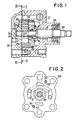
- FIGS. 1 to 4 of the drawings are views showing one embodiment of a vane pump constructed in accordance with the present invention and used in a power steering apparatus of an automotive vehicle
- a pump housing is designated by reference numeral 21 and formed with a cam ring housing portion.
- the pump housing 21 has a drive shaft 24 freely rotatably supported therein through a front bearing 23 secured to the front boss portion of the housing 21.
- the drive shaft 24 is driven to rotate about its own axis by an engine (not shown) of the automotive vehicle.
- a cam ring 26 having a cam surface 26a consisting of a large circular portion and a small circular portion, a rotor 27 freely rotatably supported within the cam surface 26a of the cam ring 26, and a front end plate 28 by which the cam ring 26 is closed at the one end thereof.
- a rear end plate 30 closing the other end of the cam ring 26 is provided to hermetically seal the pump housing 21 as a rear cover.
- the rear end plate 30 is formed at the central portion thereof with a bearing bore 32 in which a rear end portion 24a of the drive shaft 24 extending through the front end plate 28 and rotor 27 is freely rotatably supported through a rear bearing 31 secured to the rear end plate 30.
- the rear end plate 30 is formed with a pair of knock pin bores 33 and 33 each of which is spaced a predetermined distance from the center axis of the bearing bore 32 and which are disposed symmetrically with respect to the center axis of the bearing bore 32.
- a knock pin 34 In each of the knock pin bores 33 and 33 is press fitted a knock pin 34.
- the cam ring 26 is formed at the outer peripheral wall thereof with a pair of recess portions 35 and 35 of substantially semicircular configuration in cross section.
- the cam ring 26 is to be attached to the rear end plate 30 and the center axis of the cam surface 26a of the cam ring 26 is to be axially aligned with the center axis of the bearing bore 32 of the rear end plate 30.
- an inner peripheral wall of the cam ring housing portion 21a of the housing 21 and an outer peripheral wall of the front end plate 28 are formed with recess portions 36 and 37 of semicircular configuration in cross section, respectively.
- the semicircular recess portion 35 in formed in the outer peripheral wall of the cam ring 26, the semicircular recess portion 36 formed in the inner peripheral wall of the housing 21 and the semicircular recess portion 37 formed in the outer peripheral wall of the front end plate 28 as a whole constitute an alignment bore designated generally by reference numeral 38.
- the front end plate 28, cam ring 26 and rear end plate 30 are attached to the pump housing 21 by inserting the knock pin 34 press fitted in the rear end plate 30 in the alignment bore 38.
- the recess portion 35 may be replaced with an axial bore formed in the cam ring 26, the center axis of the axial bore being parallel to the center axis of the cam ring 26.
- the front end plate 28 and rotor 27 are inserted on the drive shaft 24 accommodated in the housing 21, and the rotor 27 is mounted on the drive shaft 24 through the spline formed in the drive shaft 24.
- the cam ring 26 is engaged with the knock pins 34 press fitted in the rear end plate 30 through the semicircular recess portion 35 formed in the cam ring 26, and is attached to the rear end plate 30.
- the center axis of bearing bore 32 in the rear end plate 30 and the center axis of the cam surface 26a are aligned with each other.
- the knock pins 34 are inserted in the alignment bores 38 constituted by the semicircular bores 35, 36 and 37 so that the cam ring 26 is accommodated in the cam ring housing portion 21a of the housing 21, and also the rear end portion 24a of the drive shaft 24 is inserted in the- bearing bore 32 of the rear end portion 30 through the bearing 31. Since the drive shaft 24 is passed through the central portion of the rotor 27, the center axis of the cam surface 26a and the center axis of the rotor 27 are aligned with each other.
- the cam ring 26 is dependent upon the knock pins 34. Consequently, only the semicircular recess portions 35 of the cam ring 26 engaged by the knock pins 34 are required to be cut accurately, and thus the accuracy is easily obtainable as compared with the aforementioned prior art.
- a pump chamber 40 defined by two adjacent vanes 29a and 29b which are located in the section between an intake port 26b and a discharge port 26c is substantially equal in volume to a pump chamber 41 defined by two adjacent vanes 29c and 29d which are located in the section between the intake port 26b and the discharge port 26c. Therefore, a differential pressure does not occur between the working oil in the pump chambers 40 and 41. For this reason, the rotor 27 is not subjected to a force caused by the differential pressure, and thus the oscillation and noise of the vane pump is considerably reduced.
- the center axis of the cam surface of the cam ring and the center axis of the rotor are capable of being aligned with each other only by engaging the cam ring with the knock pins mounted in the rear end plate. Accordingly, other accurate cutting operations are not necessary, thereby reducing the cost of production.
- the center axis of the cam surface of the cam ring and the center axis of the rotor are not offset from each other in assembling, the oscillation and noise do not occur during operation of the vane puma according to the present invention.
Landscapes
- Engineering & Computer Science (AREA)
- Mechanical Engineering (AREA)
- General Engineering & Computer Science (AREA)
- Rotary Pumps (AREA)
Claims (1)
Applications Claiming Priority (2)
| Application Number | Priority Date | Filing Date | Title |
|---|---|---|---|
| JP61117066A JP2670770B2 (ja) | 1986-05-20 | 1986-05-20 | ベーンポンプ |
| JP117066/86 | 1986-05-20 |
Publications (3)
| Publication Number | Publication Date |
|---|---|
| EP0246482A2 EP0246482A2 (fr) | 1987-11-25 |
| EP0246482A3 EP0246482A3 (en) | 1988-09-21 |
| EP0246482B1 true EP0246482B1 (fr) | 1991-02-27 |
Family
ID=14702578
Family Applications (1)
| Application Number | Title | Priority Date | Filing Date |
|---|---|---|---|
| EP87106419A Expired - Lifetime EP0246482B1 (fr) | 1986-05-20 | 1987-05-04 | Pompe à palettes |
Country Status (5)
| Country | Link |
|---|---|
| US (1) | US4842500A (fr) |
| EP (1) | EP0246482B1 (fr) |
| JP (1) | JP2670770B2 (fr) |
| KR (1) | KR950000261B1 (fr) |
| DE (1) | DE3768140D1 (fr) |
Families Citing this family (14)
| Publication number | Priority date | Publication date | Assignee | Title |
|---|---|---|---|---|
| JP2638987B2 (ja) * | 1988-08-30 | 1997-08-06 | アイシン精機株式会社 | 油圧駆動ファンシステム用油圧ポンプ |
| JPH02101088U (fr) * | 1989-01-30 | 1990-08-10 | ||
| JPH0373689U (fr) * | 1989-11-24 | 1991-07-24 | ||
| JP2963519B2 (ja) * | 1990-10-11 | 1999-10-18 | 豊田工機株式会社 | ベーンポンプ |
| US5290155A (en) * | 1991-09-03 | 1994-03-01 | Deco-Grand, Inc. | Power steering pump with balanced porting |
| US5267840A (en) * | 1991-09-03 | 1993-12-07 | Deco-Grand, Inc. | Power steering pump with balanced porting |
| DE4313282C2 (de) * | 1993-04-23 | 1998-05-20 | Balzers Pfeiffer Gmbh | Verfahren zur Herstellung eines Pumpsystems |
| JP3710227B2 (ja) * | 1995-12-06 | 2005-10-26 | カヤバ工業株式会社 | ベーンポンプ |
| JP4471805B2 (ja) * | 2004-10-06 | 2010-06-02 | カヤバ工業株式会社 | ベーンポンプ |
| JP2007162554A (ja) * | 2005-12-13 | 2007-06-28 | Kayaba Ind Co Ltd | ベーンポンプ |
| JP5786642B2 (ja) * | 2011-10-26 | 2015-09-30 | トヨタ自動車株式会社 | ステータ固定構造 |
| CN102606476B (zh) * | 2012-04-05 | 2015-01-14 | 王汉国 | 提高叶片式液压油泵工作稳定性方法 |
| JP6218653B2 (ja) * | 2014-03-13 | 2017-10-25 | Kyb株式会社 | ベーンポンプ及びその製造方法 |
| JP6581450B2 (ja) * | 2015-09-16 | 2019-09-25 | Kyb株式会社 | ベーンポンプ |
Family Cites Families (8)
| Publication number | Priority date | Publication date | Assignee | Title |
|---|---|---|---|---|
| US2733687A (en) * | 1956-02-07 | schmid | ||
| US3289601A (en) * | 1965-02-12 | 1966-12-06 | Fawick Corp | Fluid displacement device usable as a hydraulic motor or pump |
| US3632238A (en) * | 1969-09-05 | 1972-01-04 | Eaton Yale & Towne | Pump assembly |
| US4201521A (en) * | 1978-03-20 | 1980-05-06 | Trw Inc. | Pump and motor assembly |
| GB2016599B (en) * | 1978-03-03 | 1982-07-07 | Trw Inc | Rotary positive-displacement fluid machines |
| JPS5536839A (en) * | 1978-09-07 | 1980-03-14 | Kawaguchiko Seimitsu Kk | Display device in finder in single-lens reflex camera |
| DE3035663A1 (de) * | 1980-09-20 | 1982-05-13 | Robert Bosch Gmbh, 7000 Stuttgart | Zahnradmaschine (pumpe oder motor) |
| US4573890A (en) * | 1984-10-22 | 1986-03-04 | Atsugi Motor Parts Co., Ltd. | Vane pump with locating pins for cam ring |
-
1986
- 1986-05-20 JP JP61117066A patent/JP2670770B2/ja not_active Expired - Lifetime
-
1987
- 1987-04-20 KR KR1019870003783A patent/KR950000261B1/ko not_active Expired - Lifetime
- 1987-05-04 DE DE8787106419T patent/DE3768140D1/de not_active Expired - Lifetime
- 1987-05-04 EP EP87106419A patent/EP0246482B1/fr not_active Expired - Lifetime
-
1988
- 1988-08-09 US US07/230,701 patent/US4842500A/en not_active Expired - Lifetime
Also Published As
| Publication number | Publication date |
|---|---|
| DE3768140D1 (en) | 1991-04-04 |
| JP2670770B2 (ja) | 1997-10-29 |
| JPS62271982A (ja) | 1987-11-26 |
| US4842500A (en) | 1989-06-27 |
| EP0246482A3 (en) | 1988-09-21 |
| KR950000261B1 (ko) | 1995-01-12 |
| EP0246482A2 (fr) | 1987-11-25 |
| KR870011380A (ko) | 1987-12-23 |
Similar Documents
| Publication | Publication Date | Title |
|---|---|---|
| EP0246482B1 (fr) | Pompe à palettes | |
| US4505655A (en) | Vane pump with positioning pins for cam ring and side plates | |
| EP0399387A2 (fr) | Machine à palettes rotative | |
| US4443168A (en) | Gear machine centering arrangement | |
| JPH0472482A (ja) | ベーンポンプ | |
| US4573890A (en) | Vane pump with locating pins for cam ring | |
| US6634876B2 (en) | Vane pump having a vane guide | |
| US4028025A (en) | Screw pump | |
| EP0656098A1 (fr) | Pompe compacte a engrenage interieur. | |
| KR970075376A (ko) | 로터형 펌프 | |
| US5290160A (en) | Scroll type fluid machinery and assembling method of the same | |
| US5876194A (en) | Fixed-displacement vane-type hydraulic machine | |
| JP4215160B2 (ja) | 内接歯車ポンプおよびその製造方法 | |
| CA1135120A (fr) | Pompe a rotor pour fluides | |
| EP0881390B2 (fr) | Pompe à huile | |
| JP3718869B2 (ja) | 偏心型真空ポンプ | |
| JPH0727059A (ja) | ベーンポンプ | |
| KR970005854B1 (ko) | 게로터 펌프 | |
| JPS5945839B2 (ja) | 液力式の回転ピストン機械 | |
| US4960373A (en) | Fluid motor rotor assembly | |
| JP3312464B2 (ja) | ベーンポンプ | |
| JP2540545Y2 (ja) | 液体ポンプ | |
| JP2977964B2 (ja) | ベーンポンプ | |
| JPS5939989A (ja) | ベ−ン圧縮機 | |
| JP2000097166A (ja) | ベーンポンプのベーン飛び出し補助構造 |
Legal Events
| Date | Code | Title | Description |
|---|---|---|---|
| PUAI | Public reference made under article 153(3) epc to a published international application that has entered the european phase |
Free format text: ORIGINAL CODE: 0009012 |
|
| AK | Designated contracting states |
Kind code of ref document: A2 Designated state(s): DE FR GB |
|
| PUAL | Search report despatched |
Free format text: ORIGINAL CODE: 0009013 |
|
| AK | Designated contracting states |
Kind code of ref document: A3 Designated state(s): DE FR GB |
|
| 17P | Request for examination filed |
Effective date: 19881220 |
|
| 17Q | First examination report despatched |
Effective date: 19890612 |
|
| GRAA | (expected) grant |
Free format text: ORIGINAL CODE: 0009210 |
|
| AK | Designated contracting states |
Kind code of ref document: B1 Designated state(s): DE FR GB |
|
| REF | Corresponds to: |
Ref document number: 3768140 Country of ref document: DE Date of ref document: 19910404 |
|
| ET | Fr: translation filed | ||
| PLBE | No opposition filed within time limit |
Free format text: ORIGINAL CODE: 0009261 |
|
| STAA | Information on the status of an ep patent application or granted ep patent |
Free format text: STATUS: NO OPPOSITION FILED WITHIN TIME LIMIT |
|
| 26N | No opposition filed | ||
| REG | Reference to a national code |
Ref country code: GB Ref legal event code: IF02 |
|
| REG | Reference to a national code |
Ref country code: GB Ref legal event code: 732E |
|
| REG | Reference to a national code |
Ref country code: FR Ref legal event code: TP Ref country code: FR Ref legal event code: CD |
|
| PGFP | Annual fee paid to national office [announced via postgrant information from national office to epo] |
Ref country code: DE Payment date: 20060427 Year of fee payment: 20 |
|
| PGFP | Annual fee paid to national office [announced via postgrant information from national office to epo] |
Ref country code: GB Payment date: 20060503 Year of fee payment: 20 |
|
| PGFP | Annual fee paid to national office [announced via postgrant information from national office to epo] |
Ref country code: FR Payment date: 20060515 Year of fee payment: 20 |
|
| REG | Reference to a national code |
Ref country code: GB Ref legal event code: PE20 |
|
| PG25 | Lapsed in a contracting state [announced via postgrant information from national office to epo] |
Ref country code: GB Free format text: LAPSE BECAUSE OF EXPIRATION OF PROTECTION Effective date: 20070503 |