EP0246448A2 - Appareil pour le meulage ou le polissage de pièces - Google Patents
Appareil pour le meulage ou le polissage de pièces Download PDFInfo
- Publication number
- EP0246448A2 EP0246448A2 EP87105575A EP87105575A EP0246448A2 EP 0246448 A2 EP0246448 A2 EP 0246448A2 EP 87105575 A EP87105575 A EP 87105575A EP 87105575 A EP87105575 A EP 87105575A EP 0246448 A2 EP0246448 A2 EP 0246448A2
- Authority
- EP
- European Patent Office
- Prior art keywords
- grinding
- polishing
- pressure
- workpiece
- operative force
- Prior art date
- Legal status (The legal status is an assumption and is not a legal conclusion. Google has not performed a legal analysis and makes no representation as to the accuracy of the status listed.)
- Withdrawn
Links
Images
Classifications
-
- B—PERFORMING OPERATIONS; TRANSPORTING
- B24—GRINDING; POLISHING
- B24B—MACHINES, DEVICES, OR PROCESSES FOR GRINDING OR POLISHING; DRESSING OR CONDITIONING OF ABRADING SURFACES; FEEDING OF GRINDING, POLISHING, OR LAPPING AGENTS
- B24B37/00—Lapping machines or devices; Accessories
- B24B37/04—Lapping machines or devices; Accessories designed for working plane surfaces
- B24B37/042—Lapping machines or devices; Accessories designed for working plane surfaces operating processes therefor
-
- B—PERFORMING OPERATIONS; TRANSPORTING
- B24—GRINDING; POLISHING
- B24B—MACHINES, DEVICES, OR PROCESSES FOR GRINDING OR POLISHING; DRESSING OR CONDITIONING OF ABRADING SURFACES; FEEDING OF GRINDING, POLISHING, OR LAPPING AGENTS
- B24B49/00—Measuring or gauging equipment for controlling the feed movement of the grinding tool or work; Arrangements of indicating or measuring equipment, e.g. for indicating the start of the grinding operation
- B24B49/16—Measuring or gauging equipment for controlling the feed movement of the grinding tool or work; Arrangements of indicating or measuring equipment, e.g. for indicating the start of the grinding operation taking regard of the load
Definitions
- the invention relates to an apparatus for the grinding or polishing of workpieces, particularly metallographic samples, in which the workpiece is pressed against a grinding or polishing disc under the influence of an operative force which is transmitted to the workpiece, and is thereby subjected to an operative pressure, i.e. grinding or polishing pressure equal to the operative force divided by the surface area of the workpiece being ground or polished.
- an operative pressure i.e. grinding or polishing pressure equal to the operative force divided by the surface area of the workpiece being ground or polished.
- an abrasion takes place, i.e. material is removed from the surface of the sample in contact with the grinding ' Or polishing disc.
- the features characterizing the invention are that in a power transmission path for the operative force there is provided an elastically deformable transmission link, and that, at the end of the power transmission path remote from the workpiece, there is provided an activating member which is adapted, at the commencement of the grinding or polishing, to strain the elastically deformable link until a desired value of the operative force or pressure has been obtained, and then to be immobilized during the progress of the process, the apparatus further comprising means for sensing the elastic deformation of the transmission link and changes of that deformation occurring during the progress of the process, and for determining both the operative force or pressure and the abrasion depth from the values established by the sensing.
- the operative force is transmitted from a point in a locked position through the elastically deformable transmission link, the operative force will gradually drop during grinding, as the abrasion proceeds (which is as a rule advantageous), and the difference between the operative force or pressure at a given moment and the value of the operative force or pressure at the commencement of the grinding or polishing will therefore constitute a measure of the abrasion depth. Therefore, the instantaneous value of the elastic deformation of the transmission link will at any stage of the process provide a measurement of both the operative force and the abrasion depth.
- the elastic deformation of a body can, as is well known, be measured by means of simple and inexpensive transducers, such as strain-gauges or capacitive transducers, and by means of simple electronic equipment the measuring results may be processed and utilized for reading and/or process control.
- the electronic equipment may comprise a microprocessor into which parameters for controlling the process in accordance with a desired program may be read.
- the microprocessor may be programmed to re-set the activating member in such a manner that the desired reduction of the operative force or pressure is obtained, to store the value of the abrasion depth which was measured immediately before the re-setting, and after the re-setting to count the abrasion depth further up from the stored value in accordance with the reduced value of the operative force.
- Another possibility, which will often be advantageous, is to read in the desired abrasion depth as a control parameter for the process, in such a manner that the process is terminated when the desired abrasion depth has been reached.
- the electronic automatic system may in that case be programmed to interrupt the grinding operation, to initiate a dressing and thereafter to continue the grinding process. In this case, too, the value of the abrasion depth is stored during the temporary interruption, and the counting is continued from this point when the process is continued.
- the apparatus may in known manner be provided with a rotating sample holder, by means of which the workpiece is caused, during the process, to perform a circular motion about an axis eccentric to that of the grinding or polishing disc.
- an improvement of the measurement can be obtained by establishing an average value of the starting position from which the abrasion depth is calculated.
- an averaging likewise takes place for use in calculating the abrasion depth.
- the averaging may take place over a single revolution or a number of revolutions of the sample holder, depending on the abrasive element (grinding/polishing disc) being used.
- the period of averaging may be established purely electronically or by means of an angle indication signal from a revolving part.
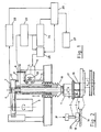
- a metallographic sample 2 is placed on a grinding/polishing disc 1 rotatably mounted in the frame of the apparatus, and is engaged by a pressing shoe 3, see also Fig. 2, at a power P which is transfer-. red from a rotating shaft 16.
- the sample is guided by a driving plate 15, which has at least one hole for receiving a sample, and through four stays 21 is fixedly connected with a sample holding head 4, which rotates together with the shaft 16.
- the rotation is effected by means of an electric motor 5.
- the shaft 16 can also be vertically moved, which must take place for placing the sample 2 on the driving plate 15, and for transmiting the required force P.
- This vertical movement is effected by means of a gear motor 12, which through a pinion 13 operates a rack 14.
- the gear motor 12 is fixedly anchored to the frame of the machine.
- the gear motor 12 is started, and the rack 14 is moved downwards.
- This movement is transferred to a bar 11 through a pivot connection.
- the bar 11 is connected with a pivoted bar 8 through a resilient bar 9.
- Two strain-gauges (half bridges) 10 are mounted on the bar 9.
- the bar 8 acts on the shaft via a bracket 17.
- the resilient bar 9 is elastically bent, and the amount of bending is sensed by the strain-gauges 10.
- the gear motor 12 is self-locking, and when it is stopped, the rack 14 is therefore immobilized in the position to which it has been moved.
- the gear motor 12, the strain-gauges 10 and the sensor 7 are connected to an electronic control comprising a comparator with Schmitt-trigger 22, a differentia-I amplifier 23, an analog/digital converter 24, a microprocessor 25, a pressure control unit 26 and a display 27 for reading the pressure and the abrasion depth.
- an electronic control comprising a comparator with Schmitt-trigger 22, a differentia-I amplifier 23, an analog/digital converter 24, a microprocessor 25, a pressure control unit 26 and a display 27 for reading the pressure and the abrasion depth.
- the surface of the sample is at 18, but as the process progresses, material is' removed, as indicated by the hatched area 19, and when the process is finished, a new surface 20 has been formed.
- the sample 2 after having been placed in the driving plate 15 connected with the sample holding head 4, is moved by the gear motor 12 towards the rotating grinding or polishing disc 1.
- the microprocessor waits for a signal from the inductive position sensor 7.
- the A/D-converter is started, and the voltage from the strain-gauge differential amplifier, which has now become an expression of the vertical position of the sample 2, is read by the microprocessor.
- the sample holding head 4 continues to rotate, new values are read in, and when the sample holding head has rotated precisely 360 0 , which is read by the position sensor 7, the average value is calculated. This value is now an expression of the initial vertical position of the sample.
- one averaging after the other is executed, and when the difference between the averaging calculation last performed and that representing the initial position is equal to the specified abrasion depth, the grinding/polishing process is stopped.
- the measuring principle depends on whether a grinding stone or a polishing disc is being used.
- the grinding stone it suffices to average over 360°, because the stone has been dressed in the same apparatus so that the vertical position of the sample is independent of the rotation of the grinding stone.
- the polishing disc no such dressing takes place, and the position of the sample will therefore depend not only on the rotation of the sample holding head, but also on the rotation of the polishing disc.
- the averaging must therefore be performed over a much larger number of revolutions of the sample holding head, so that the contribution from the polishing disc itself is included in the averaging function.
- the pressure per sample may vary from 50-60N in the case of grinding or rough polishing to 3N in the case of fine polishing.
- the drop of pressure depends on the coefficient of resiliency of the resilient bar 9. In a typical case, the drop of pressure may amount to 3N per 0.1 mm downward movement of the sample 2. For a depth 19 of removal of material amounting to 0.2 mm this will result in a pressure reduction of 12% at a final pressure of 50N.
- the quantity of material removed from the sample will normally be of the order of 0.1 to 0.5 mm.
- the abrasion depth will be determined within a tolerance of ⁇ 5 ⁇ m to ⁇ 10 ⁇ m depending on the mechanical and electronic construction of the machine.
Landscapes
- Engineering & Computer Science (AREA)
- Mechanical Engineering (AREA)
- Constituent Portions Of Griding Lathes, Driving, Sensing And Control (AREA)
- Grinding And Polishing Of Tertiary Curved Surfaces And Surfaces With Complex Shapes (AREA)
- Sampling And Sample Adjustment (AREA)
- Grinding-Machine Dressing And Accessory Apparatuses (AREA)
Applications Claiming Priority (2)
| Application Number | Priority Date | Filing Date | Title |
|---|---|---|---|
| DK1805/86 | 1986-04-18 | ||
| DK180586A DK155299B (da) | 1986-04-18 | 1986-04-18 | Apparat til slibning eller polering af emner |
Publications (2)
| Publication Number | Publication Date |
|---|---|
| EP0246448A2 true EP0246448A2 (fr) | 1987-11-25 |
| EP0246448A3 EP0246448A3 (fr) | 1989-07-05 |
Family
ID=8108182
Family Applications (1)
| Application Number | Title | Priority Date | Filing Date |
|---|---|---|---|
| EP87105575A Withdrawn EP0246448A3 (fr) | 1986-04-18 | 1987-04-15 | Appareil pour le meulage ou le polissage de pièces |
Country Status (4)
| Country | Link |
|---|---|
| US (1) | US4771578A (fr) |
| EP (1) | EP0246448A3 (fr) |
| JP (1) | JPS62251071A (fr) |
| DK (1) | DK155299B (fr) |
Cited By (1)
| Publication number | Priority date | Publication date | Assignee | Title |
|---|---|---|---|---|
| KR100825562B1 (ko) * | 2006-12-19 | 2008-04-25 | 주식회사 포스코 | 시편 가공 장치 |
Families Citing this family (23)
| Publication number | Priority date | Publication date | Assignee | Title |
|---|---|---|---|---|
| US4895033A (en) * | 1987-12-21 | 1990-01-23 | Voss Jorgen T | Sample holder for use in the grinding or polishing of samples |
| US5010692A (en) * | 1987-12-22 | 1991-04-30 | Sintobrator, Ltd. | Polishing device |
| US4873792A (en) * | 1988-06-01 | 1989-10-17 | Buehler, Ltd. | Polishing apparatus |
| US5083401A (en) * | 1988-08-08 | 1992-01-28 | Mitsubishi Denki Kabushiki Kaisha | Method of polishing |
| JPH04193443A (ja) * | 1990-11-26 | 1992-07-13 | Brother Ind Ltd | 工作機械用補助装置 |
| US5214884A (en) * | 1991-04-23 | 1993-06-01 | Kabushiki Kaisha Toshiba | Ball polishing apparatus and method for the same |
| US5800254A (en) * | 1996-04-01 | 1998-09-01 | Buehler Ltd. | Automatic apparatus for grinding and polishing samples |
| US5718619A (en) * | 1996-10-09 | 1998-02-17 | Cmi International, Inc. | Abrasive machining assembly |
| JPH11138426A (ja) * | 1997-11-11 | 1999-05-25 | Tokyo Electron Ltd | 研磨装置 |
| US6083082A (en) * | 1999-08-30 | 2000-07-04 | Lam Research Corporation | Spindle assembly for force controlled polishing |
| US6257957B1 (en) | 1999-12-01 | 2001-07-10 | Gerber Coburn Optical Inc. | Tactile feedback system |
| JP3663348B2 (ja) | 2000-09-26 | 2005-06-22 | Towa株式会社 | 研磨装置及び研磨方法 |
| CN101708590B (zh) * | 2009-11-26 | 2012-02-22 | 上海大学 | 金相试样自动磨抛机 |
| CN101758448B (zh) * | 2009-12-30 | 2011-07-27 | 东南大学 | 电化学电极抛光装置 |
| CN102059634B (zh) * | 2010-11-24 | 2012-10-31 | 山东建筑大学 | 全工位智能化金相试样制备装置 |
| CN102756327A (zh) * | 2012-07-21 | 2012-10-31 | 深圳市华测检测技术股份有限公司 | 便携式半自动研磨抛光设备 |
| CN103586772B (zh) * | 2012-08-16 | 2016-01-06 | 鸿富锦精密工业(深圳)有限公司 | 压力检测装置 |
| CN104330294B (zh) * | 2014-10-28 | 2016-10-19 | 山东科技大学 | 一种金相试样制备仪 |
| CN105834872B (zh) * | 2016-04-05 | 2017-10-24 | 西南石油大学 | 一种金相试样抛光机 |
| CN106217217B (zh) * | 2016-08-10 | 2018-06-01 | 江苏大学 | 一种恒压力并自动校正消除划痕的精密金相研磨抛光装置 |
| CN108535070A (zh) * | 2018-05-10 | 2018-09-14 | 江苏大学 | 一种激光打孔微孔截面和内壁质量分析制样装置及方法 |
| CN112223067A (zh) * | 2020-07-29 | 2021-01-15 | 莱州市蔚仪试验器械制造有限公司 | 增加试样磨削量控制的多用途磨抛机 |
| CN115078049B (zh) * | 2022-08-19 | 2022-11-04 | 深圳市聚鑫视科技有限公司 | 一种金相样品自动制样研磨方法及系统 |
Citations (3)
| Publication number | Priority date | Publication date | Assignee | Title |
|---|---|---|---|---|
| US3702043A (en) * | 1969-12-11 | 1972-11-07 | Cav Ltd | Lapping, honing or the like machines |
| DE2950881A1 (de) * | 1979-12-18 | 1981-06-25 | Fa. Peter Wolters, 2370 Rendsburg | Vorrichtung zum steuern einer werkzeugmaschine, deren werkzeug gegenueber dem werkstueck um eine achse rotiert und in dieser achse vorschiebbar ist |
| US4545153A (en) * | 1983-12-12 | 1985-10-08 | Charlton Associates | Force sensor for controlling polishing pad pressure |
Family Cites Families (2)
| Publication number | Priority date | Publication date | Assignee | Title |
|---|---|---|---|---|
| US3100954A (en) * | 1962-03-20 | 1963-08-20 | Lella Paul Di | Grinding machine |
| US3224148A (en) * | 1963-08-05 | 1965-12-21 | George A Mitchell | Method and apparatus for producing a reflective rotating shutter |
-
1986
- 1986-04-18 DK DK180586A patent/DK155299B/da not_active Application Discontinuation
-
1987
- 1987-04-15 EP EP87105575A patent/EP0246448A3/fr not_active Withdrawn
- 1987-04-15 JP JP62092965A patent/JPS62251071A/ja active Pending
- 1987-04-17 US US07/040,535 patent/US4771578A/en not_active Expired - Fee Related
Patent Citations (3)
| Publication number | Priority date | Publication date | Assignee | Title |
|---|---|---|---|---|
| US3702043A (en) * | 1969-12-11 | 1972-11-07 | Cav Ltd | Lapping, honing or the like machines |
| DE2950881A1 (de) * | 1979-12-18 | 1981-06-25 | Fa. Peter Wolters, 2370 Rendsburg | Vorrichtung zum steuern einer werkzeugmaschine, deren werkzeug gegenueber dem werkstueck um eine achse rotiert und in dieser achse vorschiebbar ist |
| US4545153A (en) * | 1983-12-12 | 1985-10-08 | Charlton Associates | Force sensor for controlling polishing pad pressure |
Cited By (1)
| Publication number | Priority date | Publication date | Assignee | Title |
|---|---|---|---|---|
| KR100825562B1 (ko) * | 2006-12-19 | 2008-04-25 | 주식회사 포스코 | 시편 가공 장치 |
Also Published As
| Publication number | Publication date |
|---|---|
| DK180586A (da) | 1987-10-19 |
| US4771578A (en) | 1988-09-20 |
| JPS62251071A (ja) | 1987-10-31 |
| EP0246448A3 (fr) | 1989-07-05 |
| DK180586D0 (da) | 1986-04-18 |
| DK155299B (da) | 1989-03-20 |
Similar Documents
| Publication | Publication Date | Title |
|---|---|---|
| US4771578A (en) | Apparatus for the grinding or polishing of workpieces | |
| US4802285A (en) | Method and apparatus for ascertaining the radial location of a new wheel profile to be produced by a reprofiling operation | |
| JP5675778B2 (ja) | 表面形状の測定方法および装置 | |
| EP0460282A1 (fr) | Meule possédant une surveillance de meulage et fonctions de contrôle automatique de l'équilibrage de la meule | |
| JPH0230823B2 (fr) | ||
| CA2125686C (fr) | Appareil de mesure de l'epaisseur d'une couche de pate et methode connexe | |
| US3902283A (en) | Gem grinder with approach control means | |
| US6848969B2 (en) | Method and device for treating spectacle glasses by means of a CNC-controlled spectacle glass treatment machine | |
| US3818642A (en) | Grinding machine | |
| US6205371B1 (en) | Method and apparatus for detecting machining flaws, especially caused by grinding machines | |
| EP0329087A1 (fr) | Méthode et dispositif pour finisage sur machine pour rectifier une surface cylindrique intérieure | |
| US5157878A (en) | Polishing method with error correction | |
| US4420910A (en) | Control device for a grinding machine | |
| EP0235021B1 (fr) | Dispositif de meulage de lentille | |
| US4820092A (en) | Touch sensing method and apparatus | |
| US4458660A (en) | Apparatus and methods for preparing grinding wheels and performing grinding operations therewith | |
| JPS63102872A (ja) | 研削方法 | |
| EP0481935A2 (fr) | Méthode et appareil pour le contrôle dans une machine à roder des deux côtés d'une pièce après son usinage | |
| EP0791873B1 (fr) | Méthode et appareil de meulage pour des pièces cylindriques | |
| KR100843921B1 (ko) | 롤의 연삭량 측정장치 | |
| JP3448311B2 (ja) | マシニングセンタの制御方法および制御装置 | |
| JPS60238265A (ja) | 面取り用砥石及びそれを有する玉摺機 | |
| JPH0335064B2 (fr) | ||
| JPH07186044A (ja) | 砥石振れ計測装置および砥石ツルーイング装置 | |
| JPH09508326A (ja) | 試料から物質構造サンプルを切断するための装置 |
Legal Events
| Date | Code | Title | Description |
|---|---|---|---|
| PUAI | Public reference made under article 153(3) epc to a published international application that has entered the european phase |
Free format text: ORIGINAL CODE: 0009012 |
|
| AK | Designated contracting states |
Kind code of ref document: A2 Designated state(s): DE FR GB |
|
| PUAL | Search report despatched |
Free format text: ORIGINAL CODE: 0009013 |
|
| AK | Designated contracting states |
Kind code of ref document: A3 Designated state(s): DE FR GB |
|
| 17P | Request for examination filed |
Effective date: 19891223 |
|
| 17Q | First examination report despatched |
Effective date: 19910114 |
|
| STAA | Information on the status of an ep patent application or granted ep patent |
Free format text: STATUS: THE APPLICATION IS DEEMED TO BE WITHDRAWN |
|
| 18D | Application deemed to be withdrawn |
Effective date: 19920904 |
|
| RIN1 | Information on inventor provided before grant (corrected) |
Inventor name: KISBOLL, KLAUS Inventor name: JORGENSEN, GERT |