EP0246437A2 - Machine, especially a sheet planer - Google Patents
Machine, especially a sheet planer Download PDFInfo
- Publication number
- EP0246437A2 EP0246437A2 EP87105023A EP87105023A EP0246437A2 EP 0246437 A2 EP0246437 A2 EP 0246437A2 EP 87105023 A EP87105023 A EP 87105023A EP 87105023 A EP87105023 A EP 87105023A EP 0246437 A2 EP0246437 A2 EP 0246437A2
- Authority
- EP
- European Patent Office
- Prior art keywords
- bearing
- cutter head
- machine according
- carrier
- journal
- Prior art date
- Legal status (The legal status is an assumption and is not a legal conclusion. Google has not performed a legal analysis and makes no representation as to the accuracy of the status listed.)
- Withdrawn
Links
Images


Classifications
-
- B—PERFORMING OPERATIONS; TRANSPORTING
- B23—MACHINE TOOLS; METAL-WORKING NOT OTHERWISE PROVIDED FOR
- B23D—PLANING; SLOTTING; SHEARING; BROACHING; SAWING; FILING; SCRAPING; LIKE OPERATIONS FOR WORKING METAL BY REMOVING MATERIAL, NOT OTHERWISE PROVIDED FOR
- B23D1/00—Planing or slotting machines cutting by relative movement of the tool and workpiece in a horizontal straight line only
Definitions
- the invention relates to a machine, preferably a moulder, according to the preamble of claim 1.
- the cutter head is pushed onto a spindle of the machine.
- the cutter head is provided with an axially and centrally opening bore.
- the cutter head has a relatively large diameter. It has also been shown that the achievable speed is limited with the cutter heads seated on spindles.
- the invention has for its object to design the generic machine so that it can work with a very high speed of the cutter head with a compact design and the ability to easily and easily replace and replace the cutter head.
- the cutter head is no longer seated on the machine spindle, but instead is rotatably mounted directly in the bearings with its front journals. This results in a very high dynamic stability, so that the cutter head can be driven at a much higher speed than in the known designs, which sit on a spindle. Since the cutter head has no bore for a spindle, its diameter can be kept small, so that the machine according to the invention can be made compact. Due to the very high speed of the cutter head, a smaller number of knives is sufficient for the usual feeds, so that the acquisition costs for such a cutter head are low and the grinding costs for regrinding the knives can be kept low. Since the one bearing is adjustable, the cutter head can be easily exchanged and replaced. This process can easily be carried out by a robot. The changeover times for replacing the cutter head can therefore be kept very short.
- the machines described below have a rotating cutter head that can be easily stored and quickly inserted into the corresponding tool storage. No spindle is provided for the cutter head; rather, the cutter head is provided on the end face with bearing journals with which the cutter head can be stored in the tool storage.
- the machines are preferably moulders, but can also be other machines with rotating cutter heads, such as planing machines and the like.
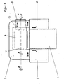
- a stand 1 along which a carriage 2 and 6 can be moved vertically in the direction of arrows a and b. They carry a carrier 3 which is horizontally displaceable on the carriage 2, 6 in the direction of arrow c.
- a cutter head 4 is rotatably supported, which is driven in rotation by a drive A. So that the cutter head 4 can be removed from the carrier 3, a clutch K (not shown in more detail) is provided between the drive A and the cutter head 4.
- the cutter head 4 has bearing pins 10, 10, on its two end faces, of which the bearing pin 10 is rotatable in a bearing bush 5 and the bearing pin 10 ⁇ in a bearing (not shown) is stored.
- the journals 10, 10 ⁇ are frustoconical, so that they center the cutter head 4 in its installed position.
- a force acting in the direction of the arrow F is applied to the bearing bush 5, by means of which the knife head 4 is clamped in its installed position.
- the force F can be applied by resilient parts, preferably by a piston-cylinder device.
- the bearing bush 5 is axially displaced in the direction of the double arrow d.
- the bearing bush 5 is guided in the carrier 3 and can be moved so far to replace the cutter head that it can be removed from the carrier 3 transversely to the axial direction or inserted into it.
- the carrier 3 is adjusted in the direction of arrow c. If a vertical adjustment of the cutter head 4 is necessary, the carrier 3 with the carriages 2 and 6 is moved in the direction of the arrows a and b along the stand 1.
- the bearing bush 5 is provided on the other side of the carrier 3, that is to say on the drive side.
- the clutch K is located in the bearing bush 5.
- this embodiment is of the same design as the embodiment according to FIG. 1.
- FIG. 3 shows a machine whose stand 1a is of the same design as in the exemplary embodiment according to FIG. 1.
- the carrier 3a is guided vertically displaceably on the stand 1a in the direction of arrow a, b.
- the carrier 3a is approximately C-shaped.
- the bearing bush 5 is accommodated, in which the tool head 4 is rotatably mounted with its journal 10a.
- the bearing bush 5 In the other leg 12 of the carrier 3a there is a bearing 13 which receives the other journal 10a ⁇ of the cutter head 4.
- the bearing pins 10a, 10a 10 are cylindrical.
- the bearing bush 5 is guided axially displaceably in an opening 14 in the carrier leg 11.
- the bearing bush 5 is in turn loaded in the direction of arrow F when the cutter head 4 is to be clamped.
- the bearing bush 5 is also provided with a bearing 13 ⁇ , which receives the journal 10a.
- the bearing bush 5 can be moved axially out of the opening 14 of the carrier leg 11. Since the diameter of the opening 14 is larger than the diameter of the cutter head 4, it can be easily changed through the large opening.
- the carrier 3a with the clamped cutter head 4 can be displaced vertically in the direction of the arrows a, b along the stand 1a.
- spacer rings 15 are provided which have different thicknesses in accordance with the required changes in position. They are inserted between the bearing 13 in the carrier leg 12 and the end face of the cutter head 4 and clamped between these two parts when the cutter head 4 is installed.
- the cutter head 5b is also axially displaceable by one Axis 17 lying parallel to the axis 16 of the cutter head 4 can be pivoted.
- One end is attached to an arm 7, which in turn is firmly connected to the bearing bush 5b.
- the arm 7 is penetrated by a locking pin 9 which is axially displaceably mounted in the arm and with which the arm can be locked in its various positions on the carrier 3b.
- the carrier 3b is provided with a plug opening 20 into which the securing bolt 9 engages in the working position of the bearing bush 5b.
- the carrier 3b with the cutter head 4 and the bearing bush 5b is otherwise of the same design as in the embodiment according to FIG. 3. It can be displaced vertically along the stand 1b in the direction of the arrows a and b.
- the bearing 13 is accommodated for the one bearing journal 10b ⁇ of the cutter head 4, while the other support leg 11b has the opening 14b for the bearing bush 5b.
- the bearing bush 5b is pushed axially out of the opening 14b until it is completely free of the opening.
- the guide rod 8, which is firmly connected to the bearing bush 5b via the arm 7, is also displaced in the guide parts 18 and 19 on the carrier 3b.
- the bearing bush 5b comes out of the opening 14b, it is pivoted laterally about the axis 17 away from the region of the opening 14 (dashed lines in FIG. 4B).
- On the carrier 3b there is a holder part 21 with a in the area next to the guide parts 18 and 19 Plug-in opening into which the safety bolt 9 is inserted in the swiveled-up position to secure the bearing bush 5b.
- the cutter head 4 can be pulled out of the bearing 13 without difficulty through the opening 14b. If the cutter head 4 is to be inserted into the carrier 3b, then the bearing bush 5b is also pivoted up and locked. Through the opening 14b, the cutter head can then be conveniently inserted into the bearing 13 with its bearing pin 10b ⁇ . In this case, the corresponding spacer ring 15 is inserted between the bearing 13 and the end face of the cutter head 4 and is clamped between the bearing 13 and the cutter head when the cutter head is clamped. As soon as the cutter head 4 with its bearing pin 10b ⁇ has been pushed into the bearing 13, the securing bolt 9 is withdrawn so that it is released from the holder part 21. The arm 7 can therefore be pivoted downwards with the bearing bush 5b.
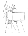
- FIGS. 5 and 6 show in detail the cutter head 4 with a further embodiment of a tool storage.
- the bearing 13 lies between an inner ring 22 and an outer ring 23.
- the two rings 22, 23 are accommodated in the carrier 3, 3a, 3b.
- the inner ring 22 has on its side facing the cutter head 4 at least two axially protruding pins 24 which engage in corresponding recesses 25 in the adjacent end face 26 of the cutter head in the installed position.
- the pins 24 are provided on an end-side, radially outwardly directed flange 27 of the inner ring 22, which is at a short distance opposite an end-side, radially inward-directed flange 28 of the outer ring 23.
- the bearing 13 is secured axially between the two rings 22, 23 by retaining rings 29 and 30. In the illustrated embodiment, two bearings 13 are arranged axially next to one another.
- the opposite bearing 13 ⁇ - in the exemplary embodiment again two axially adjacent bearings - is located between an inner ring 32 and an outer ring 31.
- the outer ring 31 has a radially inwardly directed flange 33 at the end, which has a small radial distance from an end-side, radially outwardly directed flange 34 of the inner ring 32 is opposite.
- the flange 34 of the inner ring 32 in turn has at least two axially projecting pins 35 which engage in recesses 36 in the end face 37 of the cutter head 4 in the installed position.
- the bearings 13 ⁇ are in turn axially secured by retaining rings 38 and 39 between the two rings 31 and 32.
- the outer ring 31 bears against the inner wall of the bearing bush 5.
- the bearing 13 ⁇ with the two rings 31, 32 is axially displaced with the handle 41 against the force of the compression spring 42.
- the bearing bush 5 is also axially displaced.
- the maximum displacement of the bearing and bearing bush corresponds to twice the length of the journal 10 or 10 ⁇ . This ensures that the bearing pin 10 completely emerges from the bearing bush 5 and from the bearing 13, so that the cutter head 4 can be removed from the carrier 3 without difficulty.
- the bearing pins 10, 10 ⁇ are designed as so-called hydraulic bushes. They are characterized in that they have a thin wall section 44 on the circumference, under which a pressure medium space 45 is located. Radially extending feed bores 46 open into it and connect to an axially extending central bore 47. It passes through the cutter head 4 and extends to the opposite journal 10 ⁇ , which is designed in the same way as the journal 10. When the tool body 4 is inserted into the bearings 13, 13 ⁇ , pressure medium is introduced into the spaces 45 through the bores 47, 46, as a result of which the wall sections 44 are pressed firmly against the inner wall of the inner rings 22, 31, so that the cutter head 4 is clamped properly is.
- the feed lines 46, 47 are connected to a pressure medium source.
- the cutter head 4 can be installed and removed with a robot, for example.
- the slot 40 is so long that the bearing 13 ⁇ can be moved by twice the length of the journal 10, 10 ⁇ . The cutter head 4 can then be replaced without difficulty.
- the bearing 13 ⁇ is not mounted in a bearing bush, but directly in the carrier 3, 3a, 3b. Even then, the bearing can be easily moved to replace the cutter head 4.
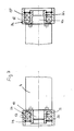
- FIG. 7 shows two possibilities for the formation of the bearing journals of the cutter head 4.
- the cutter head can have the cylindrical bearing journals, as is shown in the left half in FIG. 7.
- This journal 10 is housed in the bearings 13, which in turn are axially secured by the locking rings 29, 30 in the rings 22 and 23.
- the outer ring 23 is longer than the inner ring 22, as is also the case for the outer ring 31 of the embodiment according to FIGS. 5 and 6.
- the outer ring 23 is axially displaceably accommodated in the bearing bush (not shown), so that the bearing can be pushed off by cylindrical bearing journals 10 of the cutter head 4.
- the bearing journal 10c shown on the right side of FIG. 7 is frustoconical.
- the inner ring 32c has an inner lying on the surface of an imaginary cone surface 48 on which the bearing pin 10c rests in the installed position.
- the cone angle of the journal 10c is smaller than the angle of self-locking, so that the cutter head 4 can be pulled out of the bearing 13 ⁇ without difficulty.
- the outer ring 31c and the inner ring 32c are of the same design as in the embodiment according to FIGS. 5 and 6.
- the (not shown) bearing bush of the respective bearing is subjected to force (see, for example, FIG. 3), so that the cutter head 4 with its bearing journal 10, 10c is pressed into the inner ring 22, 32c and clamped .
- the cutter head 4 Since in the described embodiments the cutter head 4 is not mounted on a spindle, but is mounted directly in the corresponding bearings via the end journals, the dynamic stability obtained thereby enables the cutter head to be operated at a very high speed, this speed being up to approximately Can be 12,000 rpm. can. This enables very high feed speeds of the workpieces to be machined with the cutter head to be achieved. Since the cutter head 4 does not require an axial bore - because it is not pushed onto a spindle - the diameter of the cutter head can be small, so that the machine equipped with such a cutter head can be made compact.
- the cutter heads 4 can be replaced quickly and easily.
- the sliding Bearing bushing 5, 5b is clamped in the installed position of the cutter head by suitable, known means. If the trunnion 10c is frustoconical, the cutter head 4 must be axially preloaded, for which springs, hydraulic or pneumatic piston-cylinder arrangements, eccentrics or the like can be provided, which exert the corresponding axial feed forces on the bearing bush. If, however, the bearing journals 10, 10 ⁇ are designed as solid cylinder journals (FIGS.
Abstract
Description
Die Erfindung betrifft eine Maschine, vorzugsweise eine Kehlmaschine, nach dem Oberbegriff des Anspruches 1.The invention relates to a machine, preferably a moulder, according to the preamble of
Bei solchen Maschinen wird der Messerkopf auf eine Spindel der Maschine aufgeschoben. Der Messerkopf ist hierzu mit einer axial und zentral veralufenden Bohrung versehen. Infolge dieser Bohrung hat der Messerkopf einen verhältnismäßig großen Durchmesser. Auch hat sich gezeigt, daß mit den auf Spindeln sitzenden Messerköpfen die erreichbare Drehzahl begrenzt ist.In such machines, the cutter head is pushed onto a spindle of the machine. For this purpose, the cutter head is provided with an axially and centrally opening bore. As a result of this drilling, the cutter head has a relatively large diameter. It has also been shown that the achievable speed is limited with the cutter heads seated on spindles.
Der Erfindung liegt die Aufgabe zugrunde, die gattungsgemäße Maschine so auszubilden, daß sie bei kompakter Ausbildung und der Möglichkeit, den Messerkopf leicht und einfach ein- und auswechseln zu können, mit einer sehr hohen Drehzahl des Messerkopfes arbeiten kann.The invention has for its object to design the generic machine so that it can work with a very high speed of the cutter head with a compact design and the ability to easily and easily replace and replace the cutter head.
Diese Aufgabe wird bei der gattungsgemäßen Maschine erfindungsgemäß mit den kennzeichnenden Merkmalen des Anspruches 1 gelöst.This object is achieved in the generic machine according to the invention with the characterizing features of
Bei der erfindungsgemäßen Maschine sitzt der Messerkopf nicht mehr auf der Maschinenspindel, sondern wird mit seinen stirnseitig angeordneten Lagerzapfen unmittelbar in den Lagern drehbar gelagert. Dadurch ergibt sich eine sehr hohe dynamische Stabilität, so daß der Messerkopf mit einer wesentlich höheren Drehzahl angetrieben werden kann als bei den bekannten Ausführungen, die auf einer Spindel sitzen. Da der Messerkopf keine Bohrung für eine Spindel aufweist, kann sein Durchmesser klein gehalten werden, so daß die erfindungsgemäße Maschine kompakt ausgebildet werden kann. Infolge der sehr hohen Drehzahl des Messerkopfes genügt bei den üblichen Vorschüben eine geringere Zahl von Messern, so daß die Anschaffungskosten für einen solchen Messerkopf gering sind und die Schleifkosten zum Nachschleifen der Messer klein gehalten werden können. Da das eine Lager verstellbar ist, kann der Messerkopf einfach ein- und ausgewechselt werden. Dieser Vorgang kann ohne weiteres von einem Roboter vorgenommen werden. Die Umrüstzeiten zum Auswechseln des Messerkopfes können darum sehr gering gehalten werden.In the machine according to the invention, the cutter head is no longer seated on the machine spindle, but instead is rotatably mounted directly in the bearings with its front journals. This results in a very high dynamic stability, so that the cutter head can be driven at a much higher speed than in the known designs, which sit on a spindle. Since the cutter head has no bore for a spindle, its diameter can be kept small, so that the machine according to the invention can be made compact. Due to the very high speed of the cutter head, a smaller number of knives is sufficient for the usual feeds, so that the acquisition costs for such a cutter head are low and the grinding costs for regrinding the knives can be kept low. Since the one bearing is adjustable, the cutter head can be easily exchanged and replaced. This process can easily be carried out by a robot. The changeover times for replacing the cutter head can therefore be kept very short.
Weitere Merkmale der Erfindung ergeben sich aus den weiteren Ansprüchen, der Beschreibung und den Zeichnungen.Further features of the invention result from the further claims, the description and the drawings.
Die Erfindung wird anhand einiger in den Zeichnungen dargestellter Ausführungsformen näher erläutert. Es zeigen
- Fig. 1 in schematischer Darstellung eine erste Ausführungsform einer erfindungsgemäßen Maschine,
- Fig. 2 in schematischer Darstellung eine zweite Ausführungsform einer erfindungsgemäßen Maschine,
- Fig. 3 in schematischer Darstellung eine dritte Ausführungsform einer erfindungsgemäßen Maschine,
- Fig. 4A in schematischer Darstellung eine vierte Ausführungsform einer erfindungsgemäßen Maschine,
- Fig. 4B eine Ansicht in Richtung des Pfeiles IV in Fig. 4A,
- Fig. 5 teilweise im Axialschnitt und teilweise in Ansicht eine Lagerung eines Werkzeuges der erfindungsgemäßen Maschine,
- Fig. 6 eine Stirnansicht des Werkzeuges gemäß Fig. 5,
- Fig. 7 teilweise im Axialschnitt und teilweise in Ansicht einen Teil einer weiteren Ausführungsform einer Werkzeuglagerung der erfindungsgemäßen Maschine.
- 1 shows a schematic representation of a first embodiment of a machine according to the invention,
- 2 shows a schematic representation of a second embodiment of a machine according to the invention,
- 3 shows a schematic representation of a third embodiment of a machine according to the invention,
- 4A is a schematic representation of a fourth embodiment of a machine according to the invention,
- 4B is a view in the direction of arrow IV in Fig. 4A,
- 5 partly in axial section and partly in view a bearing of a tool of the machine according to the invention,
- 6 shows an end view of the tool according to FIG. 5,
- Fig. 7 partly in axial section and partly in view a part of a further embodiment of a tool storage of the machine according to the invention.
Die im folgenden beschriebenen Maschinen haben einen rotierenden Messerkopf, der in einfacher Weise gelagert und in die entsprechende Werkzeuglagerung rasch eingesetzt werden kann. Für den Messerkopf ist keine Spindel vorgesehen; vielmehr ist der Messerkopf stirnseitig mit Lagerzapfen versehen, mit denen der Messerkopf in der Werkzeuglagerung gelagert werden kann. Die Maschinen sind vorzugsweise Kehlmaschinen, können aber auch andere Maschinen mit drehbaren Messerköpfen sein, wie etwa Hobelwerkmaschinen und dergleichen.The machines described below have a rotating cutter head that can be easily stored and quickly inserted into the corresponding tool storage. No spindle is provided for the cutter head; rather, the cutter head is provided on the end face with bearing journals with which the cutter head can be stored in the tool storage. The machines are preferably moulders, but can also be other machines with rotating cutter heads, such as planing machines and the like.
Die Maschine gemäß Fig. 1 hat einen Ständer 1, längs dem in Pfeilrichtung a und b jeweils ein Schlitten 2 und 6 vertikal verfahrbar ist. Sie tragen einen Träger 3, der in Pfeilrichtung c horizontal auf den Schlitten 2, 6 verschiebbar ist. Im Träger 3 ist ein Messerkopf 4 drehbar gelagert, der von einem Antrieb A rotierend angetrieben wird. Damit der Messerkopf 4 aus dem Träger 3 herausgenommen werden kann, ist zwischen dem Antrieb A und dem Messerkopf 4 eine (nicht näher dargestellte) Kupplung K vorgesehen. Der Messerkopf 4 weist an seinen beiden Stirnseiten Lagerzapfen 10, 10ʹ auf, von denen der Lagerzapfen 10 in einer Lagerbuchse 5 und der Lagerzapfen 10ʹ in einem (nicht dargestellten) Lager drehbar gelagert ist. Die Lagerzapfen 10, 10ʹ sind kegelstumpfförmig ausgebildet, so daß sie den Messerkopf 4 in seiner Einbaulage zentrieren. Zum Einspannen des Werkzeugkopfes 4 wird auf die Lagerbuchse 5 eine in Richtung des Pfeiles F wirkende Kraft aufgebracht, durch welche der Messerkopf 4 in seiner Einbaulage eingespannt wird. Die Kraft F kann durch federnde Teile, vorzugsweise durch eine Kolben-Zylinder-Vorrichtung aufgebracht werden. Zum Einspannen oder zum Ausbau des Messerkopfes 4 wird die Lagerbuchse 5 in Richtung des Doppelpfeiles d axial verschoben. Hierbei ist die Lagerbuchse 5 im Träger 3 geführt und kann zum Auswechseln des Messerkopfes so weit verschoben werden, daß er quer zur Achsrichtung aus dem Träger 3 herausgenommen bzw. in ihn eingesetzt werden kann.1 has a
Zur Axialverstellung des Messerkopfes 4 wird der Träger 3 in Pfeilrichtung c verstellt. Ist eine Vertikalverstellung des Messerkopfes 4 notwendig, dann wird der Träger 3 mit den Schlitten 2 und 6 in Pfeilrichtung a und b längs des Ständers 1 verschoben.For the axial adjustment of the
Bei der Ausführungsform gemäß Fig. 2 ist die Lagerbuchse 5 auf der anderen Seite des Trägers 3, das heißt auf der Antriebsseite, vorgesehen. In diesem Falle befindet sich die Kupplung K in der Lagerbuchse 5. Im übrigen ist diese Ausführungsform gleich ausgebildet wie das Ausführungsbeispiel nach Fig. 1.In the embodiment according to FIG. 2, the
Fig. 3 zeigt eine Maschine, deren Ständer 1a gleich ausgebildet ist wie beim Ausführungsbeispiel nach Fig. 1. Der Träger 3a ist jedoch unmittelbar am Ständer 1a in Pfeilrichtung a, b vertikal verfahrbar geführt. Der Träger 3a hat etwa C-Form. In seinem einen Schenkel 11 ist die Lagerbuchse 5 untergebracht, in welcher der Werkzeugkopf 4 mit seinem Lagerzapfen 10a drehbar gelagert ist. Im anderen Schenkel 12 des Trägers 3a befindet sich ein Lager 13, das den anderen Lagerzapfen 10aʹ des Messerkopfes 4 aufnimmt. Im Gegensatz zu den beiden zuvor beschriebenen Ausführungsbeispielen sind die Lagerzapfen 10a, 10aʹ zylindrisch ausgebildet. Die Lagerbuchse 5 ist in einer Öffnung 14 im Trägerschenkel 11 axial verschiebbar geführt. Die Lagerbuchse 5 wird wiederum in Richtung des Pfeiles F belastet, wenn der Messerkopf 4 eingespannt werden soll. Die Lagerbuchse 5 ist ebenfalls mit einem Lager 13ʹ versehen, das den Lagerzapfen 10a aufnimmt.FIG. 3 shows a machine whose stand 1a is of the same design as in the exemplary embodiment according to FIG. 1. However, the carrier 3a is guided vertically displaceably on the stand 1a in the direction of arrow a, b. The carrier 3a is approximately C-shaped. In one
Zum Auswechseln des Messerkopfes 4 kann die Lagerbuchse 5 axial aus der Öffnung 14 des Trägerschenkels 11 herausgefahren werden. Da der Durchmesser der Öffnung 14 größer ist als der Durchmesser des Messerkopfes 4, läßt er sich bequem durch die große Öffnung wechseln. Der Träger 3a mit dem eingespannten Messerkopf 4 kann in Richtung der Pfeile a, b längs des Ständers 1a vertikal verschoben werden. Zur Axialeinstellung des Messerkopfes 4 sind Distanzringe 15 vorgesehen, die entsprechend den erforderlichen Lageveränderungen unterschiedliche Dicke haben. Sie werden zwischen dem Lager 13 im Trägerschenkel 12 und der Stirnseite des Messerkopfes 4 eingesetzt und zwischen diesen beiden Teilen bei eingebautem Messerkopf 4 eingespannt.To replace the
Bei der Ausführungsform nach den Fig. 4A und 4B ist der Messerkopf 5b außer axial verschieblich auch um eine parallel zur Achse 16 des Messerkopfes 4 liegende Achse 17 schwenkbar. Auf dem Träger 3b befinden sich zwei mit Abstand hintereinander liegende Führungsteile 18 und 19 (Fig. 4A), durch welche eine Führungsstange 8 verläuft. Ihr eines Ende ist an einem Arm 7 befestigt, der seinerseits fest mit der Lagerbuchse 5b verbunden ist. Der Arm 7 wird von einem Sicherungsbolzen 9 durchsetzt, der axial verschieblich im Arm gelagert ist und mit dem der Arm in seinen verschiedenen Stellungen am Träger 3b arretiert werden kann. Der Träger 3b ist mit einer Stecköffnung 20 versehen, in welche der Sicherungsbolzen 9 in der Arbeitsstellung der Lagerbuchse 5b eingreift. Der Träger 3b mit dem Messerkopf 4 und der Lagerbuchse 5b ist im übrigen gleich ausgebildet wie bei der Ausführungsform gemäß Fig. 3. Er kann längs des Ständers 1b vertikal in Richtung der Pfeile a und b verschoben werden. Im Trägerschenkel 12b ist das Lager 13 für den einen Lagerzapfen 10bʹ des Messerkopfes 4 untegebracht, während der andere Trägerschenkel 11b die Öffnung 14b für die Lagerbuchse 5b aufweist.In the embodiment according to FIGS. 4A and 4B, the
Soll der Messerkopf 4 ausgewechselt werden, wird die Lagerbuchse 5b axial aus der Öffnung 14b geschoben, bis sie vollständig von der Öffnung freikommt. Bei diesem Verschiebevorgang wird auch die über den Arm 7 fest mit der Lagerbuchse 5b verbundene Führungsstange 8 in den Führungsteilen 18 und 19 auf dem Träger 3b verschoben. Wenn die Lagerbuchse 5b aus der Öffnung 14b freikommt, wird sie um die Achse 17 seitlich aus dem Bereich der Öffnung 14 weggeschwenkt (gestrichelte Linien in Fig. 4B). Auf dem Träger 3b befindet sich im Bereich neben den Führungsteilen 18 und 19 ein Halterteil 21 mit einer Stecköffnung, in welche der Sicherungsbolzen 9 in der hochgeschwenkten Lage zur Sicherung der Lagerbuchse 5b gesteckt wird. Nunmehr kann der Messerkopf 4 ohne Schwierigkeiten durch die Öffnung 14b aus dem Lager 13 herausgezogen werden. Soll der Messerkopf 4 in den Träger 3b eingesetzt werden, dann wird die Lagerbuchse 5b ebenfalls hochgeschwenkt und arretiert. Durch die Öffnung 14b läßt sich dann der Messerkopf bequem mit seinem Lagerzapfen 10bʹ in das Lager 13 einführen. Hierbei wird zwischen dem Lager 13 und der Stirnseite des Messerkopfes 4 der entsprechende Distanzring 15 eingelegt, der bei eingespanntem Messerkopf zwischen dem Lager 13 und dem Messerkopf eingeklemmt wird. Sobald der Messerkopf 4 mit seinem Lagerzapfen 10bʹ in das Lager 13 geschoben worden ist, wird der Sicherungsbolzen 9 zurückgezogen, so daß er vom Halterteil 21 freikommt. Der Arm 7 kann darum mit der Lagerbuchse 5b nach unten geschwenkt werden. Anschließend wird sie gegen den Messerkopf 4 axial verschoben, wobei dessen Lagerzapfen 10b in das Lager 13ʹ gelangt. Über die Rundführung 8, 18, 19 läßt sich die Lagerbuchse 5b sehr einfach axial verschieben. In der in Fig. 4A dargestellten Endlage wird der Sicherungsbolzen 9 in die Stecköffnung 20 gesteckt, so daß der Arm 7 und damit die Lagerbuchse 5b einwandfrei zentriert ist. Anschließend wird die Lagerbuchse 5b in der beschriebenen Weise mit Kraft beaufschlagt, um den Messerkopf 4 in der Werkzeuglagerung zu spannen.If the
Die Figuren 5 und 6 zeigen im einzelnen den Messerkopf 4 mit einer weiteren Ausführungsform einer Werkzeug lagerung. Das Lager 13 liegt zwischen einem Innenring 22 und einem Außenring 23. Die beiden Ringe 22, 23 sind im Träger 3, 3a, 3b untergebracht. Der Innenring 22 weist auf seiner dem Messerkopf 4 zugewandten Seite wenigstens zwei axial vorstehende Zapfen 24 auf, die in Einbaulage in entsprechende Vertiefungen 25 in der benachbarten Stirnseite 26 des Messerkopfes eingreifen. Die Zapfen 24 sind an einem endseitigen, radial nach außen gerichteten Flansch 27 des Innenringes 22 vorgesehen, der mit geringem Abstand einem endseitigen, radial nach innen gerichteten Flansch 28 des Außenringes 23 gegenüberliegt. Das Lager 13 ist durch Sicherungsringe 29 und 30 axial zwischen den beiden Ringen 22, 23 gesichert. Im dargestellten Ausführungsbeispiel sind zwei Lager 13 axial nebeneinander angeordnet.FIGS. 5 and 6 show in detail the
Das gegenüberliegende Lager 13ʹ - im Ausführungsbeispiel wieder zwei axial nebeneinander liegende Lager - liegt zwischen einem Innenring 32 und einem Außenring 31. Der Außenring 31 hat endseitig einen radial nach innen gerichteten Flansch 33, der mit geringem radialen Abstand einem endseitigen, raidal nach außen gerichteten Flansch 34 des Innenringes 32 gegenüberliegt. Der Flansch 34 des Innenringes 32 weist wiederum wenigstens zwei axial abstehende Zapfen 35 auf, die in der Einbaulage in Vertiefungen 36 in der Stirnseite 37 des Messerkopfes 4 eingreifen. Die Lager 13ʹ sind wiederum durch Sicherungsringe 38 und 39 axial zwischen den beiden Ringen 31 und 32 gesichert. Der Außenring 31 liegt an der Innenwandung der Lagerbuchse 5 an. Sie hat einen axial verlaufenden Längsschlitz 40, durch den eine am Außenring 31 vorgesehene Handhabe 41 ragt, mit der die beiden Ringe 31, 32 und das Lager 13ʹ gegen die Kraft einer Druckfeder 42 in der Lagerbuchse 5 verschoben werden können. Die Druckfeder 42 stützt sich an einem Boden 43 der Lagerbuchse 5 und am Außenring 31 ab.The opposite bearing 13ʹ - in the exemplary embodiment again two axially adjacent bearings - is located between an
Soll der Messerkopf 4 ausgewechselt werden, dann wird mit der Handhabe 41 das Lager 13ʹ mit den beiden Ringen 31, 32 gegen die Kraft der Druckfeder 42 axial verschoben. Sobald die Handhabe 41 am Schlitzende zur Anlage kommt, wird auch die Lagerbuchse 5 axial verschoben. Der maximale Verschiebeweg von Lager und Lagerbuchse entspricht der doppelten Länge des Lagerzapfens 10 bzw. 10ʹ. Dadurch ist sichergestellt, daß der Lagerzapfen 10 vollständig aus der Lagerbuchse 5 und aus dem Lager 13 heraustritt, so daß der Messerkopf 4 ohne Schwierigkeiten aus dem Träger 3 herausgenommen werden kann.If the
Bei dem in den Fig. 5 und 6 dargestellten Ausführungsbeispiel sind die Lagerzapfen 10, 10ʹ als sogenannte Hydrobuchsen ausgebildet. Sie zeichnen sich dadurch aus, daß sie einen umfangsseitigen dünnen Wandabschnitt 44 aufweisen, unter dem sich ein Druckmittelraum 45 befindet. In ihn münden radial verlaufende Zuführbohrungen 46, die an eine axial verlaufende zentrale Bohrung 47 anschließen. Sie durchsetzt den Messerkopf 4 und verläuft bis zum gegenüberliegenden Lagerzapfen 10ʹ, der in gleicher Weise wie der Lagerzapfen 10 ausgebildet ist. Wenn der Werkzeugkörper 4 in die Lager 13, 13ʹ eingesetzt ist, wird über die Bohrungen 47, 46 Druckmittel in die Räume 45 eingeleitet, wodurch die Wandabschnitte 44 fest an die Innenwandung der Innenringe 22, 31 gepreßt werden, so daß der Messerkopf 4 einwandfrei eingespannt ist. Die Zuführleitungen 46,47 sind an eine Druckmittelquelle angeschlossen.In the embodiment shown in FIGS. 5 and 6, the bearing pins 10, 10ʹ are designed as so-called hydraulic bushes. They are characterized in that they have a
Aufgrund der beschriebenen Ausbildung kann der Messerkopf 4 beispsielsweise mit einem Roboter ein- und ausgebaut werden.Because of the design described, the
Bei einer anderen (nicht dargestellten) Ausführungsform ist der Schlitz 40 so lang, daß das Lager 13ʹ um die doppelte Länge des Lagerzapfens 10, 10ʹ verschoben werden kann. Der Messerkopf 4 kann dann ohne Schwierigkeiten ausgewechselt werden.In another (not shown) embodiment, the
Bei einer weiteren (nicht dargestellten) Ausführungsform ist das Lager 13ʹ nicht in einer Lagerbuchse, sondern unmittelbar im Träger 3, 3a, 3b gelagert. Auch dann läßt sich das Lager zum Auswechseln des Messerkopfes 4 einfach verschieben.In a further embodiment (not shown), the bearing 13ʹ is not mounted in a bearing bush, but directly in the
Fig. 7 zeigt zwei Möglichkeiten der Ausbildung der Lagerzapfen des Messerkopfes 4. Der Messerkopf kann die zylindrisch ausgebildeten Lagerzapfen aufweisen, wie er in Fig. 7 in der linken Hälfte dargestellt ist. Dieser Lagerzapfen 10 ist in den Lagern 13 untergebracht, die wiederum durch die Sicherungsringe 29, 30 in den Ringen 22 und 23 axial gesichert sind. Der Außenring 23 ist länger als der Innenring 22, wie dies auch für den Außenring 31 der Ausführungsform nach den Fig. 5 und 6 der Fall ist. Der Außenring 23 ist in der (nicht dargestellten) Lagerbuchse axial verschiebbar untergebracht, so daß das Lager von zylindrischen Lagerzapfen 10 des Messerkopfes 4 abgeschoben werden kann.FIG. 7 shows two possibilities for the formation of the bearing journals of the
Der auf der rechten Seite der Fig.7 dargestellte Lagerzapfen 10c ist kegelstumpfförmig ausgebildet. Der Innenring 32c hat eine auf dem Mantel eines gedachten Kegels liegende Innen fläche 48, an der der Lagerzapfen 10c in der Einbaulage anliegt. Der Kegelwinkel des Lagerzapfen 10c ist kleiner als der Winkel der Selbsthemmung, so daß der Messerkopf 4 ohne Schwierigkeiten aus dem Lager 13ʹ herausgezogen werden kann. Im übrigen sind der Außenring 31c und der Innenring 32c gleich ausgebildet wie bei der Ausführungsform nach den Fig. 5 und 6.The
Zum Einspannen des Messerkopfes 4 wird die (nicht darge(stellte) Lagerbuchse des jeweiligen Lagers mit Kraft beaufschlagt (vgl. beispielsweise Fig. 3) , so daß der Messerkopf 4 mit seinem Lagerzapfen 10, 10c in den Innenring 22,32c gedrückt und verspannt wird.To clamp the
Da bei den beschriebenen Ausführungsformen der Messerkopf 4 nicht auf einer Spindel gelagert ist, sondern über die endseitigen Lagerzapfen direkt in den entsprechenden Lagern gelagert ist, kann infolge der dadurch gewonnenen dynamischen Stabilität mit einer sehr hohen Drehzahl des Messerkopfes gearbeitet werden, wobei diese Drehzahl bis etwa 12.000 U/min betragen kann. kann. Dadurch können sehr hohe Vorschubgeschwindigkeiten der mit dem Messerkopf zu bearbeitenden Werkstücke erreicht werden. Da der Messerkopf 4 keine Axialbohrung benötigt - weil er nicht auf eine Spindel aufgeschoben wird -, kann der Durchmesser des Messerkopfes klein sein, so daß die mit einem solchen Messerkopf ausgerüstete Maschine kompakt ausgebildet werden kann. Infolge der hohen Drehzahl des Messerkopfes ist bei den üblichen Vorschüben auch nur eine geringere Messerzahl notwendig, wodurch sich nicht nur die Anschaffungskosten, sondern auch die Schliefkosten erheblich verringern, da nur noch eine kleinere Zahl von Messern nachgeschliffen werden muß. Mit der beschriebenen Lagerung können die Messerköpfe 4 einfach und rasch ausgewechselt werden. Die verschiebbare Lagerbuchse 5, 5b wird in der Einbaulage des Messerkopfes durch geeignete, bekannte Mittel geklemmt. Ist der Lagerzapfen 10c kegelstumpfförmig ausgebildet, muß der Messerkopf 4 axial vorgespannt werden, wofür Federn, hydraulische oder pneumatische Kolben-Zylinder-Anordnungen, Exzenter oder dergleichen vorgesehen sein können, welche die entsprechenden axialen Vorschubkräfte auf die Lagerbuchse ausüben. Sind hingegen die Lagerzapfen 10, 10ʹ als massive Zylinderzapfen (Fig. 5 und 6) oder als Hydrobuchsen ausgebildet, dann ist eine axiale Verspannung des Messerkopfes nicht notwendig. Bei der Hydrobuchse wird zusätzlich durch elastische Verformung der dünnen Wandabschnitte 44 der Messerkopf axial einwandfrei in den Innering 22, 32 der Lager eingespannt.Since in the described embodiments the
Infolge der hohen dynamischen Stabilität und Steifigkeit der beschriebenen Werkzeuglagerung kann eine äußerst glatte Oberfläche der bearbeiteten Werkstücke erreicht werden, ohne daß in der Maschine Jointsteine zum Nachschleifen der Messer des Messerkopfes notwendig sind. Infolge der hohen dynamischen Steifigkeit der Werkzeuglagerung kann der Messerkopf 4 immer seine maximale Länge aufweisen. Die bei den bekannten, auf Spindel aufgeschobenen Messerköpfen bei hohen Belastungen bzw. bei dünnen und/oder langen Spindel auftretenden unregelmäßigen Hobelbilder sind bei Verwendung der beschriebenen Messerköpfe und Werkzeuglagerungen nicht zu erwarten.Due to the high dynamic stability and rigidity of the tool storage described, an extremely smooth surface of the machined workpieces can be achieved without the need for joint stones in the machine for regrinding the knives of the cutter head. As a result of the high dynamic rigidity of the tool mounting, the
Claims (13)
dadurch gekennzeichnet, daß der Messerkopf (4) stirnseitig jeweils einen Lagerzapfen (10,10ʹ; 10a, 10aʹ; 10b, 10bʹ; 10c) aufweist, der in jeweils ein Lager (13,13ʹ) einsetzbar ist, von denen zumindest ein Lager (13, 13ʹ) in eine den zugehörigen Lagerzapfen (10,10ʹ;10a,10aʹ;10b,10bʹ;10c) freigebende Lage verstellbar ist.1. machine, preferably moulder, with at least one rotatably driven cutter head, which is mounted in a tool storage and clamped in its installed position,
characterized in that the cutter head (4) has a bearing journal (10, 10ʹ; 10a, 10aʹ; 10b, 10bʹ; 10c) on the face side, which can be inserted into a respective bearing (13, 13ʹ), at least one bearing (13 , 13ʹ) in a position releasing the associated journal (10,10ʹ; 10a, 10aʹ; 10b, 10bʹ; 10c).
dadurch gekennzeichnet, daß der Lagerzapfen (10,10ʹ; 10a,10aʹ;10b,10bʹ) zylindrisch ausgebildet ist.2. Machine according to claim 1,
characterized in that the bearing pin (10, 10ʹ; 10a, 10aʹ; 10b, 10bʹ) is cylindrical.
dadurch gekennzeichnet, daß der Lagerzapfen (10,10ʹ; 10c) kegelstumpfförmig ausgebildet ist, und daß das dem kegelstumpfförmigen Lagerzapfen (10,10ʹ;10c) zugeordnete Lager (13ʹ) vorzugsweise eine auf dem Mantel eines gedachten Kegels liegende Anlagefläche (48) aufweist.3. Machine according to claim 1,
characterized in that the bearing journal (10, 10ʹ; 10c) is frustoconical, and in that the bearing (13 zugeordnet) associated with the frustoconical journal (10, 10ʹ; 10c) preferably has a contact surface (48) lying on the surface of an imaginary cone.
dadurch gekennzeichnet, daß der Kegelwinkel des Lagerzapfens (10,10ʹ;10c) kleiner ist als der Winkel der Selbsthemmung.4. Machine according to claim 3,
characterized in that the cone angle of the bearing journal (10, 10ʹ; 10c) is smaller than the angle of the self-locking.
dadurch gekennzeichnet, daß das verschiebbare Lager (13,13ʹ) in einer axial verschiebbaren Lagerbuchse (5,5b) untergebracht ist, die vorzugsweise in einem Träger (3,3a,3b), der die Lager (13,13ʹ) für den Messerkopf (4) aufweist, untergebracht und vorzugsweise in einer Schiebeführung (14, 14b) des Trägers (3, 3a, 3b) angeordnet ist.5. Machine according to one of claims 1 to 4,
characterized in that the displaceable bearing (13,13ʹ) is accommodated in an axially displaceable bearing bush (5,5b), which is preferably in a carrier (3,3a, 3b) which holds the bearings (13,13ʹ) for the cutter head ( 4), housed and preferably arranged in a sliding guide (14, 14b) of the carrier (3, 3a, 3b).
dadurch gekennzeichnet, daß die Lagerbuchse (5b) um eine parallel zur Achse (16) des Messerkopfes (4) liegende Achse (17) schwenkbar ist und vorzugsweise einen quer zu ihrer Achse verlaufenden Arm (7) aufweist, der mit einer weiteren Schiebeführung (8,18,19) fest verbunden ist.6. Machine according to claim 5,
characterized in that the bearing bush (5b) can be pivoted about an axis (17) lying parallel to the axis (16) of the cutter head (4) and preferably has an arm (7) running transversely to its axis, which is connected to a further sliding guide (8 , 18,19) is firmly connected.
dadurch gekennzeichnet, daß die weitere Schiebeführung (8,18,19) eine Führungsstange (8) aufweist, deren Achse vorzugsweise die Schwenkachse (17) der Lagerbuchse (5b) bildet, und die insbesondere in mindestens einem Führungsteil (18,19) verschiebbar ist, der vorzugsweise auf dem Träger (3b) vorgesehen ist.7. Machine according to claim 6,
characterized in that the further sliding guide (8, 18, 19) has a guide rod (8), the axis of which preferably forms the pivot axis (17) of the bearing bush (5b), and which can be displaced in particular in at least one guide part (18, 19) , which is preferably provided on the carrier (3b).
dadurch gekennzeichnet, daß der Träger (3,3a,3b) mit dem Messerkopf (4) vertikal verstellbar ist.8. Machine according to one of claims 5 to 7,
characterized in that the carrier (3, 3a, 3b) is vertically adjustable with the cutter head (4).
dadurch gekennzeichnet, daß der Träger (3) horizontal verstellbar ist.9. Machine according to one of claims 5 to 8,
characterized in that the carrier (3) is horizontally adjustable.
dadurch gekennzeichnet, daß zur Axialverstellung des Messerkopfes (4) relativ zum Träger (3a) Distanzringe (15) vorgesehen sind, die zwischen dem Messerkopf (4) und dem Träger (3a) eingespannt sind.10. Machine according to one of claims 5 to 9,
characterized in that for the axial adjustment of the cutter head (4) relative to the carrier (3a) spacer rings (15) are provided which are clamped between the cutter head (4) and the carrier (3a).
dadurch gekennzeichnet, daß das Lager (13ʹ) gegen Federkraft verschiebbar ist.11. Machine according to one of claims 1 to 10,
characterized in that the bearing (13ʹ) is displaceable against spring force.
dadurch gekennzeichnet, daß das Lager (13ʹ) relativ zur Lagerbuchse (5) verschiebbar ist und vorzugsweise einen Schlitz (40) aufweist, durch den eine mit dem Lager (13ʹ) verbundene Handhabe (41) ragt, mit der das Lager (13ʹ) und die Lagerbuchse (5) verschiebbar sind.12. Machine according to one of claims 1 to 11,
characterized in that the bearing (13ʹ) is displaceable relative to the bearing bush (5) and preferably has a slot (40) through which a handle (41) connected to the bearing (13ʹ) projects, with which the bearing (13ʹ) and the bearing bush (5) can be moved.
dadurch gekennzeichnet, daß der Lagerzapfen (10,10ʹ) einen elastisch verformbaren Wandabschnitt (44) aufweist, der mindestens einen Druckraum (45) abschließt, der über Zuführleitungen (46,47) mit einer Druckmittelquelle verbunden ist.13. Machine according to one of claims 1 to 12,
characterized in that the bearing journal (10, 10ʹ) has an elastically deformable wall section (44) which closes off at least one pressure chamber (45) which is connected to a pressure medium source via supply lines (46, 47).
Applications Claiming Priority (2)
| Application Number | Priority Date | Filing Date | Title |
|---|---|---|---|
| DE19863617004 DE3617004A1 (en) | 1986-05-21 | 1986-05-21 | MACHINE, PREFERABLY MOLDING MACHINE |
| DE3617004 | 1986-05-21 |
Publications (2)
| Publication Number | Publication Date |
|---|---|
| EP0246437A2 true EP0246437A2 (en) | 1987-11-25 |
| EP0246437A3 EP0246437A3 (en) | 1989-12-06 |
Family
ID=6301254
Family Applications (1)
| Application Number | Title | Priority Date | Filing Date |
|---|---|---|---|
| EP87105023A Withdrawn EP0246437A3 (en) | 1986-05-21 | 1987-04-04 | Machine, especially a sheet planer |
Country Status (2)
| Country | Link |
|---|---|
| EP (1) | EP0246437A3 (en) |
| DE (1) | DE3617004A1 (en) |
Cited By (2)
| Publication number | Priority date | Publication date | Assignee | Title |
|---|---|---|---|---|
| DE102007018713A1 (en) * | 2007-04-16 | 2008-10-23 | Michael Weinig Ag | Milling machine and lifting device for tools for use with a moulder |
| US7919038B2 (en) | 2007-02-22 | 2011-04-05 | The Procter & Gamble Company | Method of surface treating particulate material using electromagnetic radiation |
Citations (7)
| Publication number | Priority date | Publication date | Assignee | Title |
|---|---|---|---|---|
| US1406843A (en) * | 1920-08-06 | 1922-02-14 | Anton Vonnegut | Cutter-head spindle for planers and molders |
| US1407520A (en) * | 1922-02-21 | Assictog to anton | ||
| US1426492A (en) * | 1922-03-17 | 1922-08-22 | Anton Vonnegut | Removable cutter head for motor-driven molders |
| GB200889A (en) * | 1922-04-18 | 1923-07-18 | Thomas White & Sons Ltd | Improvements in wood working machine tools |
| GB281898A (en) * | 1927-02-02 | 1927-12-15 | John Pickles & Son Engineers L | An improvement in or relating to the mounting of cutter blocks in woodworking machines |
| US2873776A (en) * | 1951-10-08 | 1959-02-17 | Rockwell Mfg Co | Planer and attachments therefor |
| EP0126284A1 (en) * | 1983-05-24 | 1984-11-28 | Black & Decker Overseas AG | Planing machine, especially an electric hand plane |
-
1986
- 1986-05-21 DE DE19863617004 patent/DE3617004A1/en not_active Withdrawn
-
1987
- 1987-04-04 EP EP87105023A patent/EP0246437A3/en not_active Withdrawn
Patent Citations (7)
| Publication number | Priority date | Publication date | Assignee | Title |
|---|---|---|---|---|
| US1407520A (en) * | 1922-02-21 | Assictog to anton | ||
| US1406843A (en) * | 1920-08-06 | 1922-02-14 | Anton Vonnegut | Cutter-head spindle for planers and molders |
| US1426492A (en) * | 1922-03-17 | 1922-08-22 | Anton Vonnegut | Removable cutter head for motor-driven molders |
| GB200889A (en) * | 1922-04-18 | 1923-07-18 | Thomas White & Sons Ltd | Improvements in wood working machine tools |
| GB281898A (en) * | 1927-02-02 | 1927-12-15 | John Pickles & Son Engineers L | An improvement in or relating to the mounting of cutter blocks in woodworking machines |
| US2873776A (en) * | 1951-10-08 | 1959-02-17 | Rockwell Mfg Co | Planer and attachments therefor |
| EP0126284A1 (en) * | 1983-05-24 | 1984-11-28 | Black & Decker Overseas AG | Planing machine, especially an electric hand plane |
Cited By (2)
| Publication number | Priority date | Publication date | Assignee | Title |
|---|---|---|---|---|
| US7919038B2 (en) | 2007-02-22 | 2011-04-05 | The Procter & Gamble Company | Method of surface treating particulate material using electromagnetic radiation |
| DE102007018713A1 (en) * | 2007-04-16 | 2008-10-23 | Michael Weinig Ag | Milling machine and lifting device for tools for use with a moulder |
Also Published As
| Publication number | Publication date |
|---|---|
| DE3617004A1 (en) | 1987-11-26 |
| EP0246437A3 (en) | 1989-12-06 |
Similar Documents
| Publication | Publication Date | Title |
|---|---|---|
| DE19830903A1 (en) | Device and method for machining bores in a workpiece using such a device | |
| DE4028775C1 (en) | ||
| EP0981416B1 (en) | Tool with a base body and method for forming bores in a work piece using such a tool | |
| DE4339754C1 (en) | Device for making bores in a dish or a rim of a motor-vehicle wheel | |
| DE2341663A1 (en) | ROTATING TOOL FOR WOODWORKING MACHINES, IN PARTICULAR CHIPPING TOOLS SUCH AS KNIFE HEAD OR CUTTER, WITH A CENTRAL HOLE FOR A DRIVE SHAFT OF THE MACHINING MACHINE | |
| DE2338207A1 (en) | MULTI-SPINDLE AUTOMATIC, IN PARTICULAR MULTI-SPINDLE LATHE | |
| DE3131107A1 (en) | Device for adjusting the axis of rotation of a joint for the swivellable suspension of a radius arm of a wheel on the body of a motor vehicle | |
| DE1577366B1 (en) | Cylindrical grinding machine for the simultaneous processing of two rotating workpieces with one rotating tool | |
| DE2559145C3 (en) | Deburring tool | |
| DE3434308A1 (en) | Chuck | |
| DE3605913A1 (en) | FOR SLOT MILLING ADJUSTABLE TOOL HOLDER ON MACHINE TOOLS | |
| DE3316283C2 (en) | Deep drilling machine | |
| EP0246437A2 (en) | Machine, especially a sheet planer | |
| DE1143689B (en) | Guide and clamping device for support sleeves in the headstock of milling and / or boring mills | |
| DE2105667A1 (en) | Machine tool | |
| DE2341396B2 (en) | Grooving milling machine | |
| DE1086661B (en) | Internal thread rolling head | |
| DE3446826A1 (en) | JAW CHUCK FOR LATHE TO MACHINE WORKPIECES UNDER SEVERAL MACHINING AXES | |
| DE4241208C2 (en) | Cutting tool for producing a longitudinal groove | |
| DE1577366C (en) | Cylindrical grinding machine for the simultaneous processing of two rotating work pieces with one rotating tool | |
| DE2004715A1 (en) | Rotatable jig | |
| DE3608141C2 (en) | ||
| DE2022226A1 (en) | Device for producing grooves in bores | |
| DE1477040A1 (en) | Tool holder for rolling tools | |
| DE2503284A1 (en) | Bore machining roller lathe - has roller unit drive shafts individually driven by motor and adjustable reduction gear |
Legal Events
| Date | Code | Title | Description |
|---|---|---|---|
| PUAI | Public reference made under article 153(3) epc to a published international application that has entered the european phase |
Free format text: ORIGINAL CODE: 0009012 |
|
| AK | Designated contracting states |
Kind code of ref document: A2 Designated state(s): AT BE CH DE ES FR GB GR IT LI LU NL SE |
|
| PUAL | Search report despatched |
Free format text: ORIGINAL CODE: 0009013 |
|
| AK | Designated contracting states |
Kind code of ref document: A3 Designated state(s): AT BE CH DE ES FR GB GR IT LI LU NL SE |
|
| RHK1 | Main classification (correction) |
Ipc: B23Q 1/08 |
|
| RAP1 | Party data changed (applicant data changed or rights of an application transferred) |
Owner name: MICHAEL WEINIG AKTIENGESELLSCHAFT |
|
| STAA | Information on the status of an ep patent application or granted ep patent |
Free format text: STATUS: THE APPLICATION IS DEEMED TO BE WITHDRAWN |
|
| 18D | Application deemed to be withdrawn |
Effective date: 19900607 |
|
| RIN1 | Information on inventor provided before grant (corrected) |
Inventor name: KROECHER, HARRO Inventor name: HEIERMANN, KLAUS |