EP0246093B1 - Exhaust timing control system for a two cycle engine - Google Patents
Exhaust timing control system for a two cycle engine Download PDFInfo
- Publication number
- EP0246093B1 EP0246093B1 EP87304282A EP87304282A EP0246093B1 EP 0246093 B1 EP0246093 B1 EP 0246093B1 EP 87304282 A EP87304282 A EP 87304282A EP 87304282 A EP87304282 A EP 87304282A EP 0246093 B1 EP0246093 B1 EP 0246093B1
- Authority
- EP
- European Patent Office
- Prior art keywords
- exhaust timing
- engine
- timing member
- cpu
- cycle
- Prior art date
- Legal status (The legal status is an assumption and is not a legal conclusion. Google has not performed a legal analysis and makes no representation as to the accuracy of the status listed.)
- Expired - Lifetime
Links
Images


Classifications
-
- F—MECHANICAL ENGINEERING; LIGHTING; HEATING; WEAPONS; BLASTING
- F02—COMBUSTION ENGINES; HOT-GAS OR COMBUSTION-PRODUCT ENGINE PLANTS
- F02D—CONTROLLING COMBUSTION ENGINES
- F02D13/00—Controlling the engine output power by varying inlet or exhaust valve operating characteristics, e.g. timing
- F02D13/02—Controlling the engine output power by varying inlet or exhaust valve operating characteristics, e.g. timing during engine operation
- F02D13/028—Controlling the engine output power by varying inlet or exhaust valve operating characteristics, e.g. timing during engine operation for two-stroke engines
- F02D13/0284—Variable control of exhaust valves only
-
- F—MECHANICAL ENGINEERING; LIGHTING; HEATING; WEAPONS; BLASTING
- F02—COMBUSTION ENGINES; HOT-GAS OR COMBUSTION-PRODUCT ENGINE PLANTS
- F02B—INTERNAL-COMBUSTION PISTON ENGINES; COMBUSTION ENGINES IN GENERAL
- F02B75/00—Other engines
- F02B75/02—Engines characterised by their cycles, e.g. six-stroke
- F02B2075/022—Engines characterised by their cycles, e.g. six-stroke having less than six strokes per cycle
- F02B2075/025—Engines characterised by their cycles, e.g. six-stroke having less than six strokes per cycle two
-
- Y—GENERAL TAGGING OF NEW TECHNOLOGICAL DEVELOPMENTS; GENERAL TAGGING OF CROSS-SECTIONAL TECHNOLOGIES SPANNING OVER SEVERAL SECTIONS OF THE IPC; TECHNICAL SUBJECTS COVERED BY FORMER USPC CROSS-REFERENCE ART COLLECTIONS [XRACs] AND DIGESTS
- Y02—TECHNOLOGIES OR APPLICATIONS FOR MITIGATION OR ADAPTATION AGAINST CLIMATE CHANGE
- Y02T—CLIMATE CHANGE MITIGATION TECHNOLOGIES RELATED TO TRANSPORTATION
- Y02T10/00—Road transport of goods or passengers
- Y02T10/10—Internal combustion engine [ICE] based vehicles
- Y02T10/12—Improving ICE efficiencies
Definitions
- the present invention relates to an apparatus and method for controlling an exhaust timing member in a two cycle engine.
- Japanese utility model laid open 51-39112(39112/1976) discloses an exhaust timing control device which controls the initiation of the exhaust cycle in a two cycle engine to increase power.
- This exhaust timing control device is provided with a member which can move the position of an upper edge of an exhaust port in a two cycle engine. The member controls the timing edge location of the exhaust port in accordance with the speed of the engine to adjust the exhaust timing.
- the aforementioned member itself cooperates closely with the wall of the combustion chamber of the engine. Thus, its operation may be affected by carbon buildup from combustion in the engine, dust in the engine oil, etc.
- EP-A-174149 Another exhaust timing control device is described in EP-A-174149, wherein a member moves between an open and a closed position, in which the timing edge is in a high or low position respectively, dependent on whether the engine speed is above or below a preset value.
- the member's position may depend on throttle opening, and to enable the engine to start without undue torque, a second low engine speed may be set below which the member is held slightly open.
- a method of controlling an exhaust timing member in a two cycle engine comprising the steps of controlling the location of the exhaust timing member responsive to engine speed between first and second position limits; monitoring engine speed; initiating a self-cleaning cycle when engine speed is above a predetermined value; driving the exhaust timing member in said cycle sequentially to the first position limit and the second position limit; and disabling said cycle.
- the invention also provides an exhaust timing controller for controlling an exhaust timing member in a two cycle engine, comprising a control circuit having means for generating a working control signal as a function of engine condition, means for providing a self-cleaning cycle by generating a fully open control signal and a fully closed control signal sequentially and independently of engine condition, and means for initiating said self-cleaning cycle when the engine is running at or greater than a selected engine speed; and means operatively connected to said control circuit for driving the exhaust timing member in response to said control signals.
- the present invention is directed to an exhaust timing control system and method for a two cycle engine which provides for smooth engine operation.
- An exhaust timing member is controlled to undergo alternating movement between position limits by a timing member drive mechanism when the speed of the engine exceeds a preselected value.
- the system may then operate responsive to certain engine parameters between the position limits.
- a cleaning cycle may be effected along with appropriate exhaust timig control.
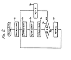
- a motor may be employed to actuate the timing member and may in turn be controlled by a voltage generator circuit actuated by signals from a CPU within a control circuit.
- the control circuit may include wave shaping, memory, A/D conversion, throttle interface, and ignition key switch setting circuits.
- the foregoing circuitry may receive ignition pulse, throttle, and timing member position data input to the control circuit. Through a series of programmed steps the CPU within the control circuit can activate the voltage generator circuit causing the motor, through the timing member driving mechanism, to move the timing member to a desired position.
- an exhaust control system includes a mechanism 1 for driving an exhaust timing member (not shown) to adjust the position of an upper edge of an exhaust port in a two cycle engine.
- Means for driving the exhaust timing member include a direct current motor 2.
- a motor driving voltage V M is supplied to the motor 2 from a control circuit 4 so as to move the exhaust timing member to create the desired port opening.
- the control circuit 4 determines the motor driving voltage V M from a plurality of inputs.
- An ignition pulse P Ne obtained from an ignition circuit (not shown) and having a frequency proportional to the rotational frequency of the engine is input to the control circuit 4.
- the ignition circuit may be, for example, a capacitor discharge type.
- a signal TH o from a throttle switch (not shown), activated when the engine throttle is opened to or beyond a preset amount.
- a voltage V ⁇ from an exhaust timing member position sensor 5 which includes, for example, a potentiometer R is input to the control circuit 4
- the position of the exhaust timing member may include and the control system may differentiate among a first position limit or fully closed position ⁇ s , a middle position ⁇ p and a second position limit or fully open position ⁇ o .
- the initiation of the exhaust cycle is earliest in the fully open position ⁇ o and is retarded as the exhaust timing member is moved toward the fully closed position ⁇ s .
- the middle position ⁇ p is not limited to one value. Rather, it may include a plurality of middle positions according to the rotational frequency of the engine irrespective of the throttle seetting.
- the control circuit 4 includes a microcomputer in which a CPU 10 and memories RAM 11 and ROM 12 or the like are connected in a well known manner via bus lines.
- the ignition pulse P Ne is processed by a wave shaping circuit 13 having, e.g., a one shot multivibrator and by a flip-flop circuit 14, with the ignition pulse P Ne being received into the CPU 10 as rotational frequency data Ne(N).
- the throttle signal TH o in this embodiment reflecting a fully open throttle, is simultaneously supplied to an appropriate port of the CPU 10 via an interface circuit 15.
- the exhaust timing member position sensor 5 generates an angular position signal V ⁇ which indicates, for example, the position or angle of rotation of the electric motor 2, or the displacement from a reference position of an appropriate member of the exhaust timing mechanism 1.
- the angular position signal V ⁇ is digitized by an A/D converter 16 and is received into the CPU 10 as data ⁇ v (N) via a bus line.
- the CPU 10 determines an optimum opening for the exhaust timing member and supplies command voltage data V o corresponding to this optimum opening to a driving voltage generator circuit 17.
- the command voltage data V o includes bits which indicate respectively the plus and minus polarity of the voltage and its magnitude.
- the driving voltage generator circuit 17 generates a motor driving voltage V M supplied to the electric motor 2 on the basis of the data V o .
- a key switch 18 such as an ignition switch facilitates providing the CPU 10 with commands which set a desired initialized condition in a main routine, as further described hereinafter.
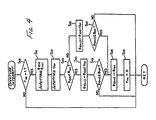
- FIG. 2 is a flow chart showing the CPU routine for adjusting the opening of the exhaust timing member. This routine is synchronized with a clock pulse from a self-contained clock generator in the CPU 10.
- a power voltage is supplied from a regulated power supply (not shown) to the control circuit 4, for example, by switching on an ignition switch, thereby activating the control circuit 4.
- the clock pulse is generated from the self-contained clock generator circuit, and the routine is performed with each clock pulse.
- the initialization function is performed immediately after turning on the power supply (step S1).
- This initialization function is that usually carried out in a microcomputer and, for example, includes a function for setting an initial provisional target value for the timing member position ⁇ T (n).
- the provisional target position ⁇ T (n) is set from memory (step S2).
- the provisional target position ⁇ T (n) is either established as part of the initializing function or is calculated in the overflow interrupt routine discussed hereinafter with reference to Figure 4 as in turn based on the values calculated in the flow chart of Figure 3.
- a value ⁇ v (N) of the actual measured exhaust timing member position is then received (step S3).
- the difference ⁇ (including the plus and minus signs) between ⁇ T (n) and the ⁇ v (N) is derived (step S4), and the absolute value of the difference / ⁇ / and a threshold value ⁇ r are compared (step S5).
- step S6 If / ⁇ / is smaller than the threshold value ⁇ r, the output voltage data V o is set at zero (step S6) and step S2 is reentered taking in ⁇ T (n).
- the threshold value ⁇ r is determined taking into account a maximum possible margin of error supposing that ⁇ T (n) and ⁇ v (N) have coincided with each other, and ideally, ⁇ r is zero.
- ⁇ / > ⁇ r the opening of the exhaust timing member has not reached the desired position. Accordingly, an output voltage V o having a value proportional to the difference ⁇ (step S7) is generated.
- the driving voltage generator circuit 17 when receiving the data V o set by the main routine, drives the electric motor 2 by bringing the value of the motor driving voltage V M to 0, -V M , or +V M , according to the value of V o (either O, -K. ⁇ , or +K. ⁇ ). The electric motor 2 is then correspondingly stopped, or turns in a reverse or forward direction. The actual position of the exhaust timing member is accordingly changed to the desired position by the operation of the driving mechanism 1.
- one or the other of the plus and minus power voltage V M or neither may be connected according to the value of V o to the output terminal.
- FIG. 3 is a flow chart demonstrating a subroutine performed for every ingnition pulse P Ne in the CPU 10.
- a self-contained counter is triggered by the ignition pulse P Ne so as to count the rotational frequency, or speed, of the engine Ne(m) with the data showing a reciprocal of a pulse distance between the ignition pulses P Ne (step S10).
- the just determined speed Ne(m) is compared with a minimum required engine speed Ne(sc) beyond idle, for example, 1500 rpm. If Ne(m) ⁇ Ne(sc) the self-cleaning operation is not performed since the rotational speed of the engine is not sufficient. If the self-cleaning operation were to be performed before the rotational speed of the engine is high enough, the fully open state of the exhaust timing member would temporarily occur and the rotational speed of the engine may become unstable.
- the self-cleaning complete flags F sc ,F scl are set to 0 in the initialization step S1 of the main routine. It is also possible to perform a desired number of the self-cleaning functions in such a manner that the function is performed until a variable K becomes a maximum value by having F sc taken as k such that K becomes K + 1 for every termination of one-self-cleaning function cycle.
- the target value ⁇ TGT and the step size U sp are set in the rest of the soubroutine.
- the current value Ne(m) of the data of the rotational frequency is compared with a fully closed threshold value Ne s , the speed of the engine at which the timing member is desired to be fully closed, and it is determined whether the last preceding value Ne(m-1) satisfies the relationship Ne(m-1) ⁇ Ne s ⁇ Ne(m) or not (step S18). When this inequality relationship exists, it is sensed as a moment when the rotational frequency Ne of the engine has exceeded the fully closed threshold value Ne s .
- step S19 the change in speed, that is, an acceleration (dNe/dt) (Ne s ) of the rotational frequency Ne of the engine is calculated at that time (step S19).
- (dNe/dt)(Ne s ) is represented as ⁇ Ne(Ne s ).
- step S20 the presence or absence of the fully open throttle signal TH o is determined.
- U1, U2 are constant, preferably with U1 > U2.
- the control device decides whether the inequality Ne(m-1) > Ne o ⁇ Ne(m) is valid or not (step S23). If this enequality is valid, it is a moment when the rotational frequency Ne of the engine has fallen below the fully open threshold value Ne o .
- the presence of the fully open signal TH o of the throttle is determined (step S24). In the presence of TH o , the control device enters into the return function without performing other steps.
- the exhaust timing member is adapted to the middle opening position ⁇ p .
- step S27 the present value of the rotational frequency of the engine Ne(m) is compared with the fully open threshold value Ne o (step S27).
- Ne(m) is larger than Ne o
- the final target position ⁇ TGT is set at the fully open position data ⁇ o and the amount of step U sp is set at a predetermined value U ol .
- an opening and closing demand flag F RO is set up and the return function is entered (step S28).
- Ne(m) is compared with Ne s (step S29).
- Ne(m) is less than Ne s
- the final target position ⁇ TGT is set at the fully closed position ⁇ s .
- F RQ is set up and the amount of step U sp is set at a predetermined value U o2 (step S30). If Ne(m) is larger than Ne s , Ne(m) is between Ne s and Ne o , and then the presence of the fully open throttle TH o is checked (step S31).
- provisional target position ⁇ T (n) may be calculated solely on the instantaneous engine speed without including variable timing member response rates responsive to acceleration of the engine.
- a provisional target value setting mode serves to control a function mode which determines a present provisional target value ⁇ T (N).
- ⁇ T (N) is established by the function mode with respect to the finally intended or final target value ⁇ TGT such that ⁇ T (N) gradually approaches ⁇ TGT .
- the provisional target value setting mode is performed by an overflow interrupt routine which employs a timmer (not shown) to count by means of the clock self-contained in the CPU and which is performed for every desired time.
- FIG. 4 is flow chart which shows the overflow interrupt routine for execution of the provisional target value setting mode and the counting mode.
- the present provisional value ⁇ T (n) and the final target value ⁇ TGT are taken from the memory (step S41). Then, the amount of step U sp therein is received (step S42). By comparing the magnitudes of ⁇ TGT and ⁇ T (n) thus taken, a decision is made whether to open or close the timing member (step S43).
- ⁇ T (n+1) has not reached ⁇ TGT , this mode is terminated; if it has, ⁇ T (n+1) is made to be equal to ⁇ TGT (step S48), the opening and closing demand flag F RQ is set to zero to release it (step S49) and this mode is terminated.
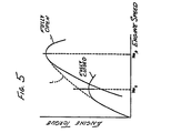
- FIG. 5 shows the relationship of engine torque to engine speed having the positioning of the timing member as a parameter.
- the timing member experiences prompt actuation and the torque rises smoothly, as shown by the dotted line L.
- FIG. 6 shows a block diagram which illustrates the operating functions of the CPU 10 shown in the flow charts of FIGS. 2 to 4.
- Operating means 20 generates the data Ne of rotational frequency on the basis of the ignition pulse P Ne .
- the data Ne of rotational frequency is compared with the fully open threshold value Ne o and the fully closed threshold value Ne s by means of first and second comparator means 21, 22.
- the Ne data is differentiated by means of differentiator means 23.
- Means 24 for setting the final target value sets ⁇ TGT according to the signal from the first and second comparator means 21, 22 and the fully open signal TH o of the throttle.
- the control device may perform the forced setting of the fully open and fully closed opening upon performing the self-cleaning operation mode, which cooperates with the signal from self-cleaning decision means 25
- Means 27 for setting the step amount operate with the signal from the comparator means 21, 22 and the differentiator means 23.
- Means 28 for setting the provisional target opening degree sets the provisionally aimed opening ⁇ T according to the step amount U sp from the means 27 for setting the step amount and according to the final target opening degree ⁇ TGT from the means 24 for setting the finally aimed opening degree.
- an exhaust timing control device for a two cycle engine wherein the opening degree of an exhaust port timing member is adjusted according to the engine operating state to effect optimum exhaust timing and a cleaning cycle is provided to prevent disabling buildups on the member.
Landscapes
- Engineering & Computer Science (AREA)
- Chemical & Material Sciences (AREA)
- Combustion & Propulsion (AREA)
- Mechanical Engineering (AREA)
- General Engineering & Computer Science (AREA)
- Output Control And Ontrol Of Special Type Engine (AREA)
- Electrical Control Of Ignition Timing (AREA)
- Valve Device For Special Equipments (AREA)
- Combined Controls Of Internal Combustion Engines (AREA)
- Control Of Throttle Valves Provided In The Intake System Or In The Exhaust System (AREA)
Description
- The present invention relates to an apparatus and method for controlling an exhaust timing member in a two cycle engine.
- Japanese utility model laid open 51-39112(39112/1976) discloses an exhaust timing control device which controls the initiation of the exhaust cycle in a two cycle engine to increase power. This exhaust timing control device is provided with a member which can move the position of an upper edge of an exhaust port in a two cycle engine. The member controls the timing edge location of the exhaust port in accordance with the speed of the engine to adjust the exhaust timing.
- The aforementioned member itself cooperates closely with the wall of the combustion chamber of the engine. Thus, its operation may be affected by carbon buildup from combustion in the engine, dust in the engine oil, etc.
- Another exhaust timing control device is described in EP-A-174149, wherein a member moves between an open and a closed position, in which the timing edge is in a high or low position respectively, dependent on whether the engine speed is above or below a preset value. The member's position may depend on throttle opening, and to enable the engine to start without undue torque, a second low engine speed may be set below which the member is held slightly open.
- According to the invention, there is provided a method of controlling an exhaust timing member in a two cycle engine, comprising the steps of
controlling the location of the exhaust timing member responsive to engine speed between first and second position limits;
monitoring engine speed;
initiating a self-cleaning cycle when engine speed is above a predetermined value;
driving the exhaust timing member in said cycle sequentially to the first position limit and the second position limit; and
disabling said cycle. - The invention also provides an exhaust timing controller for controlling an exhaust timing member in a two cycle engine, comprising
a control circuit having means for generating a working control signal as a function of engine condition, means for providing a self-cleaning cycle by generating a fully open control signal and a fully closed control signal sequentially and independently of engine condition, and means for initiating said self-cleaning cycle when the engine is running at or greater than a selected engine speed; and
means operatively connected to said control circuit for driving the exhaust timing member in response to said control signals. - Thus, the present invention is directed to an exhaust timing control system and method for a two cycle engine which provides for smooth engine operation. An exhaust timing member is controlled to undergo alternating movement between position limits by a timing member drive mechanism when the speed of the engine exceeds a preselected value. The system may then operate responsive to certain engine parameters between the position limits. Thus, a cleaning cycle may be effected along with appropriate exhaust timig control.
- A motor may be employed to actuate the timing member and may in turn be controlled by a voltage generator circuit actuated by signals from a CPU within a control circuit. In one aspect of the present invention, the control circuit may include wave shaping, memory, A/D conversion, throttle interface, and ignition key switch setting circuits. In operation, the foregoing circuitry may receive ignition pulse, throttle, and timing member position data input to the control circuit. Through a series of programmed steps the CPU within the control circuit can activate the voltage generator circuit causing the motor, through the timing member driving mechanism, to move the timing member to a desired position.
- Accordingly, it is an object of the present invention to provide improved two cycle engine operation. Other and further objects and advantages will appear hereinafter.
- An embodiment of the invention will now be described by way of example and with reference to the accompanying drawings.
- In the drawings wherein similar reference characters denote similar elements throughout the several views:
- FIG. 1 is a schematic block diagram illustrating an exhaust timing control system according to the present invention;
- FIG. 2 is a flow chart illustrating the routine in the CPU of FIG. 1 for adjusting the degree of opening of the timing member;
- FIG. 3 is a flow chart illustrating a subroutine function performed for every ignition pulse in the CPU of FIG. 1;
- FIG. 4 is a flow chart illustrating an overflow interruption routine;
- FIG. 5 is a graph plotting engine torque vs. the rotational speed of the engine, with the exhaust timing member fully open and fully closed; and
- FIG. 6 is a block diagram illustrating operating functions of the CPU in FIG. 1.
- Referring now to FIG. 1, an exhaust control system according to the present invention includes a
mechanism 1 for driving an exhaust timing member (not shown) to adjust the position of an upper edge of an exhaust port in a two cycle engine. Means for driving the exhaust timing member include a direct current motor 2. A motor driving voltage VM is supplied to the motor 2 from a control circuit 4 so as to move the exhaust timing member to create the desired port opening. The control circuit 4 determines the motor driving voltage VM from a plurality of inputs. An ignition pulse PNe obtained from an ignition circuit (not shown) and having a frequency proportional to the rotational frequency of the engine is input to the control circuit 4. The ignition circuit may be, for example, a capacitor discharge type. Also input to the control circuit 4 is a signal THo from a throttle switch (not shown), activated when the engine throttle is opened to or beyond a preset amount. Additionally, a voltage Vϑ from an exhaust timing member position sensor 5 which includes, for example, a potentiometer R is input to the control circuit 4 - The position of the exhaust timing member may include and the control system may differentiate among a first position limit or fully closed position ϑs, a middle position ϑp and a second position limit or fully open position ϑo. The initiation of the exhaust cycle is earliest in the fully open position ϑo and is retarded as the exhaust timing member is moved toward the fully closed position ϑs. Furthermore, the middle position ϑp is not limited to one value. Rather, it may include a plurality of middle positions according to the rotational frequency of the engine irrespective of the throttle seetting.
- The control circuit 4 includes a microcomputer in which a
CPU 10 andmemories RAM 11 andROM 12 or the like are connected in a well known manner via bus lines. The ignition pulse PNe is processed by awave shaping circuit 13 having, e.g., a one shot multivibrator and by a flip-flop circuit 14, with the ignition pulse PNe being received into theCPU 10 as rotational frequency data Ne(N). The throttle signal THo, in this embodiment reflecting a fully open throttle, is simultaneously supplied to an appropriate port of theCPU 10 via aninterface circuit 15. - The exhaust timing member position sensor 5 generates an angular position signal Vϑ which indicates, for example, the position or angle of rotation of the electric motor 2, or the displacement from a reference position of an appropriate member of the
exhaust timing mechanism 1. The angular position signal Vϑ is digitized by an A/D converter 16 and is received into theCPU 10 as data ϑv(N) via a bus line. - On the basis of the data Ne(N), THo, and ϑv(N), the
CPU 10 determines an optimum opening for the exhaust timing member and supplies command voltage data Vo corresponding to this optimum opening to a drivingvoltage generator circuit 17. The command voltage data Vo includes bits which indicate respectively the plus and minus polarity of the voltage and its magnitude. The drivingvoltage generator circuit 17 generates a motor driving voltage VM supplied to the electric motor 2 on the basis of the data Vo.A key switch 18 such as an ignition switch facilitates providing theCPU 10 with commands which set a desired initialized condition in a main routine, as further described hereinafter. - FIG. 2 is a flow chart showing the CPU routine for adjusting the opening of the exhaust timing member. This routine is synchronized with a clock pulse from a self-contained clock generator in the
CPU 10. - A power voltage is supplied from a regulated power supply (not shown) to the control circuit 4, for example, by switching on an ignition switch, thereby activating the control circuit 4. The clock pulse is generated from the self-contained clock generator circuit, and the routine is performed with each clock pulse. In this routine, the initialization function is performed immediately after turning on the power supply (step S₁). This initialization function is that usually carried out in a microcomputer and, for example, includes a function for setting an initial provisional target value for the timing member position ϑT(n).
- The provisional target position ϑT(n) is set from memory (step S₂). The provisional target position ϑT(n) is either established as part of the initializing function or is calculated in the overflow interrupt routine discussed hereinafter with reference to Figure 4 as in turn based on the values calculated in the flow chart of Figure 3. A value ϑv(N) of the actual measured exhaust timing member position is then received (step S₃). Then, the difference δ(including the plus and minus signs) between ϑT(n) and the ϑv(N) is derived (step S₄), and the absolute value of the difference /δ/ and a threshold value δ r are compared (step S₅). If /δ/ is smaller than the threshold value δ r, the output voltage data Vo is set at zero (step S₆) and step S₂ is reentered taking in ϑT(n). The threshold value δ r is determined taking into account a maximum possible margin of error supposing that ϑT(n) and ϑv(N) have coincided with each other, and ideally, δ r is zero. When /δ/ > δ r, the opening of the exhaust timing member has not reached the desired position. Accordingly, an output voltage Vo having a value proportional to the difference δ (step S₇) is generated.
- The driving
voltage generator circuit 17, when receiving the data Vo set by the main routine, drives the electric motor 2 by bringing the value of the motor driving voltage VM to 0, -VM, or +VM, according to the value of Vo (either O, -K.δ, or +K.δ). The electric motor 2 is then correspondingly stopped, or turns in a reverse or forward direction. The actual position of the exhaust timing member is accordingly changed to the desired position by the operation of thedriving mechanism 1. In the drivingvoltage generator circuit 17, one or the other of the plus and minus power voltage VM or neither may be connected according to the value of Vo to the output terminal. - FIG. 3 is a flow chart demonstrating a subroutine performed for every ingnition pulse PNe in the
CPU 10. In this routine, a self-contained counter is triggered by the ignition pulse PNe so as to count the rotational frequency, or speed, of the engine Ne(m) with the data showing a reciprocal of a pulse distance between the ignition pulses PNe (step S₁₀). Then, a determination is made as to whether or not a self-cleaning complete flag Fsc is present (step S₁₁). If Fsc = 1, the self-cleaning operation is not performed. If the self-cleaning complete flag is not present, Fsc = 0, the just determined speed Ne(m) is compared with a minimum required engine speed Ne(sc) beyond idle, for example, 1500 rpm. If Ne(m) < Ne(sc) the self-cleaning operation is not performed since the rotational speed of the engine is not sufficient. If the self-cleaning operation were to be performed before the rotational speed of the engine is high enough, the fully open state of the exhaust timing member would temporarily occur and the rotational speed of the engine may become unstable. - When Ne(m) ≧ Ne(sc), the self-cleaning operation is carried out. First, ϑv(N) is compared with the fully open value ϑo (step S₁₃). If ϑv(N) is not equal to ϑo, an interim-cleaning flag Fscl is checked. If the flag Fscl is not present, a target position ϑTGT is set to ϑo (step S₁₄) and the subroutine returns. Then, when ϑv(N) becomes equal to ϑo by moving the exhaust timing member open, the target position ϑTGT is reset at the fully closed value ϑTGT = ϑs (step S₁₅). The interim self-cleaning complete flag Fscl is then set. A determination is made as to whether ϑv(N) is equal to ϑs (step S₁₆). Until ϑv(N) becomes equal to ϑs, the subroutine returns by recognizing the flag Fscl and retaining ϑTGT = ϑs. When ϑv(N) = ϑs the self-cleaning operation is complete and the self-cleaning complete flag is set, Fsc = 1 (step S₁₇), and the subroutine returns.
Thus, after turning on the power supply and after N(m)≧ Ne(sc) the self-cleaning operation is performed by fully opening and then fully closing the exhaust timing member. - The self-cleaning complete flags Fsc,Fscl are set to 0 in the initialization step S₁ of the main routine. It is also possible to perform a desired number of the self-cleaning functions in such a manner that the function is performed until a variable K becomes a maximum value by having Fsc taken as k such that K becomes K + 1 for every termination of one-self-cleaning function cycle.
- When Fsc = 1, the target value ϑTGT and the step size Usp are set in the rest of the soubroutine. The current value Ne(m) of the data of the rotational frequency is compared with a fully closed threshold value Nes, the speed of the engine at which the timing member is desired to be fully closed, and it is determined whether the last preceding value Ne(m-1) satisfies the relationship Ne(m-1) < Nes ≦ Ne(m) or not (step S₁₈). When this inequality relationship exists, it is sensed as a moment when the rotational frequency Ne of the engine has exceeded the fully closed threshold value Nes. In this case, the change in speed, that is, an acceleration (dNe/dt) (Nes) of the rotational frequency Ne of the engine is calculated at that time (step S₁₉). Here, (dNe/dt)(Nes) is represented as ΔNe(Nes). Then, the presence or absence of the fully open throttle signal THo is determined (step S₂₀). In the presence of the signal THo, the amount of step Usp is selected as the fully open amount of step Uspo = U₁ ·ΔNe(Nes) (step S₂₁). In the absence of THo, the amount of step Usp is operated as the first middle opening amount of step Usppl= U₂ · ΔNe(Nes) and the subroutine returns.
- Here, U₁, U₂ are constant, preferably with U₁ > U₂.
- When the inequality Ne(m-1) < Nes ≦ N(m) does not exist, the control device decides whether the inequality Ne(m-1) > Neo ≧ Ne(m) is valid or not (step S₂₃). If this enequality is valid, it is a moment when the rotational frequency Ne of the engine has fallen below the fully open threshold value Neo. In preparation for closing the timing member, the presence of the fully open signal THo of the throttle is determined (step S₂₄). In the presence of THo, the control device enters into the return function without performing other steps. On the other hand, in the absence of the THo, the exhaust timing member is adapted to the middle opening position ϑp. After calculating (dNE/dt) (Neo) =ΔNe(Neo) (step S₂₅), the amount of step Usp is considered as the second middle amount of step, Uspp2 = U₃ · ΔNe(Neo) (step S₂₆). Further, U₃ is a constant and if U₂ = U₃, Uspp1 may equal Uspp2.
- When the inequality of step S₂₃ is not valid, the present value of the rotational frequency of the engine Ne(m) is compared with the fully open threshold value Neo (step S₂₇). When Ne(m) is larger than Neo, the final target position ϑTGT is set at the fully open position data ϑo and the amount of step Usp is set at a predetermined value Uol. Simultaneously, an opening and closing demand flag FRO is set up and the return function is entered (step S₂₈).
- When Ne(m) is less than Neo, Ne(m) is compared with Nes (step S₂₉). When Ne(m) is less than Nes, the final target position ϑTGT is set at the fully closed position ϑs. Simultaneously, FRQ is set up and the amount of step Usp is set at a predetermined value Uo2 (step S₃₀). If Ne(m) is larger than Nes, Ne(m) is between Nes and Neo, and then the presence of the fully open throttle THo is checked (step S₃₁). When THo exists, the control device checks whether the timing member is being moved toward full open, that is, whether the conditions of ϑTGT = ϑo and FRQ = 1 are satisfied or not (step S₃₂). If the conditions are valid, the return function is entered without other steps. If they are not valid, the values are set as ϑTGT = ϑo and FRQ = 1 (step S₃₃) and the subroutine returns. In the absence of the fully open throttle signal THo , the opening of the exhaust valve is set to the middle opening position ϑp, and the condition of movement to the middle opening position, that is, the condition of ϑTGT = ϑp and FRQ = 1 is established (step S₃₄). If this condition is satisfied, the return function is entered without other steps. If the condition is not satisfied, the values are set as ϑTGT = ϑp and FRQ = 1 (step S₃₅) and the subroutine returns. By the aforementioned function modes, the final intended value ϑTGT and the amount of step Usp ae continuously updated and are always the optimum value for every PNe pulse.
- Alternatively, the provisional target position ϑT(n) may be calculated solely on the instantaneous engine speed without including variable timing member response rates responsive to acceleration of the engine.
- The fow chart of FIG. 3 is performed by interrupting the main routine with every engine ignition pulse PNe. A provisional target value setting mode serves to control a function mode which determines a present provisional target value ϑT(N). ϑT(N) is established by the function mode with respect to the finally intended or final target value ϑTGT such that ϑT(N) gradually approaches ϑTGT. The provisional target value setting mode is performed by an overflow interrupt routine which employs a timmer (not shown) to count by means of the clock self-contained in the CPU and which is performed for every desired time.
- FIG. 4 is flow chart which shows the overflow interrupt routine for execution of the provisional target value setting mode and the counting mode. First, when the self-contained timer overflows, the control system determines whether the opening and closing demand flag FRQ is present (1) or not (0). If FRQ = 0, the routine returns to the main routine.
If FRQ = 1, the provisional target value setting mode is to be performed. The present provisional value ϑT (n) and the final target value ϑTGT are taken from the memory (step S₄₁). Then, the amount of step Usp therein is received (step S₄₂). By comparing the magnitudes of ϑTGT and ϑT(n) thus taken, a decision is made whether to open or close the timing member (step S₄₃). If ϑT(n) is less than ϑTGT, the provisional target value is changed by taking ϑT(n) + Usp as a final value to increase the provisional target opening degree by the amount of step Usp (step S₄₄). Conversely, if ϑT(n) is greater than ϑTGT, the provisionally aimed opening degree ϑT(n) is decreased by the amount of step Usp, as ϑT (n+ 1) = ϑT(n) - Usp (step S₄₅). Then, the magnitudes of ϑTGT and ϑT (n+1) are compared (steps S₄₆, S₄₇). If ϑT (n+1) has not reached ϑTGT, this mode is terminated; if it has, ϑT (n+1) is made to be equal to ϑTGT (step S₄₈), the opening and closing demand flag FRQ is set to zero to release it (step S₄₉) and this mode is terminated. - FIG. 5 shows the relationship of engine torque to engine speed having the positioning of the timing member as a parameter. When the engine rapidly accelerates, the timing member experiences prompt actuation and the torque rises smoothly, as shown by the dotted line L. There is no reduction in torque as would be experienced with a conventional engine with one setting or a controlled engine exhaust port with the member controlled to be either fully open or fully closed.
- FIG. 6 shows a block diagram which illustrates the operating functions of the
CPU 10 shown in the flow charts of FIGS. 2 to 4. Operating means 20 generates the data Ne of rotational frequency on the basis of the ignition pulse PNe. The data Ne of rotational frequency is compared with the fully open threshold value Neo and the fully closed threshold value Nes by means of first and second comparator means 21, 22. The Ne data is differentiated by means of differentiator means 23. Means 24 for setting the final target value sets ϑTGT according to the signal from the first and second comparator means 21, 22 and the fully open signal THo of the throttle. Further, the control device may perform the forced setting of the fully open and fully closed opening upon performing the self-cleaning operation mode, which cooperates with the signal from self-cleaning decision means 25 - Means 27 for setting the step amount operate with the signal from the comparator means 21, 22 and the differentiator means 23. Means 28 for setting the provisional target opening degree sets the provisionally aimed opening ϑT according to the step amount Usp from the
means 27 for setting the step amount and according to the final target opening degree ϑTGT from themeans 24 for setting the finally aimed opening degree. Subtraction means 29 computes the difference δ = ϑv - ϑT between the ϑT thus obtained and the real opening degree ϑv of the exhaust timing member and supplies this difference to multiplier means 30. The multiplier means 30 calculates Vo = K· δ and outputs the result as a driving voltage data Vo for the timing member. - The behavior of the circuit shown in the block diagram of FIG. 6 is adapted to actuate at the same parameters as that shown in the flow charts of FIGS. 2 to 4.
- Thus, an exhaust timing control device is disclosed for a two cycle engine wherein the opening degree of an exhaust port timing member is adjusted according to the engine operating state to effect optimum exhaust timing and a cleaning cycle is provided to prevent disabling buildups on the member. While embodiments and applications of this invention have been shown and described, it would be apparent to those skilled in the art that many more modifications are possible, without departing from the matter as herein defined in the claims.
Claims (6)
controlling the location of the exhaust timing member responsive to engine speed between first and second position limits;
monitoring engine speed;
initiating a self-cleaning cycle when engine speed is above a predetermined value;
driving the exhaust timing member in said cycle sequentially to the first position limit and the second position limit; and
disabling said cycle.
a control circuit having means for generating a working control signal as a function of engine condition, means for providing a self-cleaning cycle by generating a fully open control signal and a fully closed control signal sequentially and independently of engine condition, and means for initiating said self-cleaning cycle when the engine is running at or greater than a selected engine speed; and
means operatively connected to said control circuit for driving the exhaust timing member in response to said control signals.
said control circuit comprises a CPU, means for providing said CPU with throttle position, ignition pulse, and exhaust timing member position parameter data, and means for processing said data within said CPU to determine optimum exhaust timing member positions between fully open and fully closed limit positions based on the parameter data and generating a working control signal.
Applications Claiming Priority (2)
| Application Number | Priority Date | Filing Date | Title |
|---|---|---|---|
| JP111636/86 | 1986-05-14 | ||
| JP61111636A JPS62267515A (en) | 1986-05-14 | 1986-05-14 | Exhaust timing control device for two-cycle engine |
Publications (3)
| Publication Number | Publication Date |
|---|---|
| EP0246093A2 EP0246093A2 (en) | 1987-11-19 |
| EP0246093A3 EP0246093A3 (en) | 1989-02-08 |
| EP0246093B1 true EP0246093B1 (en) | 1991-08-28 |
Family
ID=14566330
Family Applications (1)
| Application Number | Title | Priority Date | Filing Date |
|---|---|---|---|
| EP87304282A Expired - Lifetime EP0246093B1 (en) | 1986-05-14 | 1987-05-14 | Exhaust timing control system for a two cycle engine |
Country Status (4)
| Country | Link |
|---|---|
| US (1) | US4763613A (en) |
| EP (1) | EP0246093B1 (en) |
| JP (1) | JPS62267515A (en) |
| DE (1) | DE3772445D1 (en) |
Families Citing this family (10)
| Publication number | Priority date | Publication date | Assignee | Title |
|---|---|---|---|---|
| DE3868528D1 (en) * | 1987-04-14 | 1992-04-02 | Honda Motor Co Ltd | DEVICE AND METHOD FOR EXHAUST TIME CONTROL FOR AN INTERNAL COMBUSTION ENGINE. |
| JP2595487B2 (en) * | 1988-03-25 | 1997-04-02 | スズキ株式会社 | Variable exhaust timing device |
| US5083533A (en) * | 1989-11-09 | 1992-01-28 | North American Philips Corporation | Two-stroke-cycle engine with variable valve timing |
| JPH06193450A (en) * | 1992-12-25 | 1994-07-12 | Yamaha Motor Co Ltd | Exhaust control valve device for 2-cycle engine |
| EP0706610B1 (en) * | 1993-06-30 | 2000-06-07 | Orbital Engine Company (Australia) Pty. Ltd. | Exhaust valve timing control responsive to engine knock and torque |
| US5575246A (en) * | 1993-09-22 | 1996-11-19 | Yamaha Hatsudoki Kabushiki Kaisha | Operational control device for two-cycle engines |
| JPH07224668A (en) * | 1994-02-07 | 1995-08-22 | Sanshin Ind Co Ltd | Variable compression mechanism of 2-cycle engine |
| US6216648B1 (en) * | 1999-05-14 | 2001-04-17 | Arctic Cat, Inc. | Internal combustion engine with pneumatically controlled variable exhaust valve |
| US6481394B1 (en) * | 1999-09-27 | 2002-11-19 | Sanshin Kogyo Kabushiki Kaisha | Control system for two-cycle engine |
| US8925502B1 (en) | 2010-01-22 | 2015-01-06 | Brp Us Inc. | Hydraulically actuated valve assembly for an engine |
Family Cites Families (34)
| Publication number | Priority date | Publication date | Assignee | Title |
|---|---|---|---|---|
| JPS5121038A (en) * | 1974-08-09 | 1976-02-19 | Kubota Ltd | Nainenkikanno jidogenatsusochi |
| US4121552A (en) * | 1974-09-17 | 1978-10-24 | Yamaha Hatsudoki Kabushiki Kaisha | Exhaust means for two cycle engines |
| JPS5139112A (en) * | 1974-09-30 | 1976-04-01 | Hitachi Ltd | JIKIHETSUDOYOKAKIKOMYOMIDASHIKAIRO |
| JPS5142497A (en) * | 1974-10-08 | 1976-04-10 | Dainippon Printing Co Ltd | Denkikogakuyoseruno seizoho |
| JPS584336B2 (en) * | 1974-12-24 | 1983-01-26 | キヤノン株式会社 | record body |
| JPS51147813A (en) * | 1975-06-13 | 1976-12-18 | Kubota Ltd | Operation lever for construction machine |
| JPS5218333A (en) * | 1975-08-04 | 1977-02-10 | Canon Inc | Heating device |
| JPS5852510B2 (en) * | 1976-04-27 | 1983-11-22 | 東芝テック株式会社 | printing device |
| US4202297A (en) * | 1977-06-22 | 1980-05-13 | Yamaha Hatsudoki Kabushiki Kaisha | Two-stroke engine having variable exhaust port timing |
| JPS54158514A (en) * | 1978-06-05 | 1979-12-14 | Yamaha Motor Co Ltd | Discharge time controller fir 2-cycle engine |
| JPS55160107A (en) * | 1979-05-29 | 1980-12-12 | Yamaha Motor Co Ltd | Actuating device for exhaust valve of two-cycle engine |
| JPS5627014A (en) * | 1979-08-09 | 1981-03-16 | Yamaha Motor Co Ltd | Exhaust valve device of two-cycle engine |
| JPS5647609A (en) * | 1979-09-21 | 1981-04-30 | Yamaha Motor Co Ltd | Exhaust timing controller for two-cycle engine |
| JPS5656915A (en) * | 1979-10-17 | 1981-05-19 | Yamaha Motor Co Ltd | Exhaust-valve driving system for water-cooled two-cycle engine |
| JPS5692314A (en) * | 1979-12-27 | 1981-07-27 | Yamaha Motor Co Ltd | Exhaust timing controlling apparatus for two-cycle engine |
| US4516540A (en) * | 1980-04-21 | 1985-05-14 | Outboard Marine Corporation | Two-cycle internal combustion engine including means for varying cylinder port timing |
| US4341188A (en) * | 1980-04-21 | 1982-07-27 | Outboard Marine Corporation | Two-cycle internal combustion engine including means for varying cylinder port timing |
| JPS5762917A (en) * | 1980-09-30 | 1982-04-16 | Yamaha Motor Co Ltd | Exhaust timing control device for 2-cycle engine |
| AT380538B (en) * | 1980-12-18 | 1986-06-10 | Bombardier Rotax Gmbh | DEVICE FOR CONTROLLING THE EXHAUST TIME OF TWO-STROKE COMBUSTION ENGINES |
| JPS57105511A (en) * | 1980-12-23 | 1982-07-01 | Yamaha Motor Co Ltd | Apparatus for reducing pressure at starting of internal combustion engine |
| AT369866B (en) * | 1981-04-02 | 1983-02-10 | Bombardier Rotax Gmbh | DEVICE FOR EXHAUST TIME CONTROL OF TWO-STROKE INTERNAL COMBUSTION ENGINES |
| JPS587060A (en) * | 1981-07-06 | 1983-01-14 | 株式会社ノダ | Tile construction of house wall surface |
| JPS5836818A (en) * | 1981-08-29 | 1983-03-03 | Natl House Ind Co Ltd | Member conveying mechanism |
| US4494506A (en) * | 1982-02-03 | 1985-01-22 | Mazda Motor Corporation | Intake system for an internal combustion engine |
| JPS587059A (en) * | 1982-06-18 | 1983-01-14 | 三浦 廣一 | Small piece embossing decorative material of concrete wall surface |
| JPS597008A (en) * | 1982-07-03 | 1984-01-14 | Toshiba Corp | High-density tablet and method of sealing semiconductor with resin using said tablet |
| DE3232786A1 (en) * | 1982-09-03 | 1984-04-26 | Heinz 6050 Offenbach Liebert | Device for altering the intake cross-section in a piston-controlled two-stroke internal combustion engine |
| JPS5946310A (en) * | 1982-09-10 | 1984-03-15 | Mazda Motor Corp | Valve timing control device of engine |
| JPS59105928A (en) * | 1982-12-08 | 1984-06-19 | Yamaha Motor Co Ltd | Exhaust device of two-cycle engine |
| DE3432047C2 (en) * | 1983-09-19 | 1993-11-04 | Suzuki Motor Co | TWO-STROKE MACHINE |
| JPS6098121A (en) * | 1983-11-02 | 1985-06-01 | Kawasaki Heavy Ind Ltd | Control device for exhaust port |
| JPS60141687A (en) * | 1983-12-27 | 1985-07-26 | 日産化学工業株式会社 | Surface enhancement finishing method for cementitious material |
| JPS60249614A (en) * | 1984-05-23 | 1985-12-10 | Kawasaki Heavy Ind Ltd | Exhaust port control device in two-cycle engine |
| EP0174149B1 (en) * | 1984-08-28 | 1988-09-14 | Honda Giken Kogyo Kabushiki Kaisha | Two-stroke engine with variable port timing |
-
1986
- 1986-05-14 JP JP61111636A patent/JPS62267515A/en active Granted
-
1987
- 1987-01-29 US US07/008,712 patent/US4763613A/en not_active Expired - Fee Related
- 1987-05-14 EP EP87304282A patent/EP0246093B1/en not_active Expired - Lifetime
- 1987-05-14 DE DE8787304282T patent/DE3772445D1/en not_active Expired - Lifetime
Also Published As
| Publication number | Publication date |
|---|---|
| EP0246093A3 (en) | 1989-02-08 |
| JPS62267515A (en) | 1987-11-20 |
| US4763613A (en) | 1988-08-16 |
| JPH0372813B2 (en) | 1991-11-19 |
| EP0246093A2 (en) | 1987-11-19 |
| DE3772445D1 (en) | 1991-10-02 |
Similar Documents
| Publication | Publication Date | Title |
|---|---|---|
| EP0246093B1 (en) | Exhaust timing control system for a two cycle engine | |
| US4793347A (en) | Exhaust timing control device for two cycle engines | |
| US4550277A (en) | Overload detection and warning system for electric motors in power tools and the like | |
| EP0540758B1 (en) | Apparatus for controlling the rotational speed of an engine for a vehicle | |
| SE445572B (en) | WHEEL SPEED CONTROL SYSTEM FOR MOTOR VEHICLE | |
| US4438744A (en) | Idling rpm feedback control method for internal combustion engines | |
| EP0344772A2 (en) | Method and apparatus for controlling a throttle valve of internal combustion engines | |
| JPS61278488A (en) | Sailing stabilizer for marine propeller | |
| US4453514A (en) | Engine speed adaptive air bypass valve (dashpot) control | |
| US5197433A (en) | Anticipatory intake manifold tuning valve control | |
| JPS6354132B2 (en) | ||
| US4432317A (en) | Method and apparatus for controlling the idling rotational speed of an internal combustion engine | |
| JPS6368744A (en) | Idle rotation frequency control device | |
| RU98123612A (en) | METHOD AND DEVICE FOR PREVENTION OF SURFACE WHEN TRANSFERING A TURBO COMPRESSOR FROM A PARALLEL CONNECTION TO AN OFFLINE OPERATION MODE | |
| JPS57210170A (en) | Operation controller for hydraulic machinery | |
| US5280772A (en) | Process for controlling the speed of an internal combustion engine after starting | |
| JPH0784850B2 (en) | Acceleration slip controller | |
| JPH06200763A (en) | Intake control device for internal combustion engine | |
| CA2021845A1 (en) | Engine speed control apparatus | |
| US5704328A (en) | Method to control a short runner bypass valve in the intake manifold of an internal combustion engine | |
| JPS6119946A (en) | Engine throttle control method | |
| US5392748A (en) | Ignition timing controlling device for an engine | |
| EP0877158B1 (en) | Diesel engine controller | |
| EP1228959A3 (en) | Controller for an electric outboard drive system for a watercraft | |
| JPH041434A (en) | Engine control device |
Legal Events
| Date | Code | Title | Description |
|---|---|---|---|
| PUAI | Public reference made under article 153(3) epc to a published international application that has entered the european phase |
Free format text: ORIGINAL CODE: 0009012 |
|
| AK | Designated contracting states |
Kind code of ref document: A2 Designated state(s): DE FR GB |
|
| PUAL | Search report despatched |
Free format text: ORIGINAL CODE: 0009013 |
|
| AK | Designated contracting states |
Kind code of ref document: A3 Designated state(s): DE FR GB |
|
| 17P | Request for examination filed |
Effective date: 19890207 |
|
| 17Q | First examination report despatched |
Effective date: 19900115 |
|
| GRAA | (expected) grant |
Free format text: ORIGINAL CODE: 0009210 |
|
| AK | Designated contracting states |
Kind code of ref document: B1 Designated state(s): DE FR GB |
|
| REF | Corresponds to: |
Ref document number: 3772445 Country of ref document: DE Date of ref document: 19911002 |
|
| ET | Fr: translation filed | ||
| PLBE | No opposition filed within time limit |
Free format text: ORIGINAL CODE: 0009261 |
|
| STAA | Information on the status of an ep patent application or granted ep patent |
Free format text: STATUS: NO OPPOSITION FILED WITHIN TIME LIMIT |
|
| 26N | No opposition filed | ||
| PGFP | Annual fee paid to national office [announced via postgrant information from national office to epo] |
Ref country code: DE Payment date: 19950531 Year of fee payment: 9 |
|
| PG25 | Lapsed in a contracting state [announced via postgrant information from national office to epo] |
Ref country code: DE Effective date: 19970201 |
|
| PGFP | Annual fee paid to national office [announced via postgrant information from national office to epo] |
Ref country code: GB Payment date: 19970508 Year of fee payment: 11 |
|
| PG25 | Lapsed in a contracting state [announced via postgrant information from national office to epo] |
Ref country code: GB Free format text: LAPSE BECAUSE OF NON-PAYMENT OF DUE FEES Effective date: 19980514 |
|
| GBPC | Gb: european patent ceased through non-payment of renewal fee |
Effective date: 19980514 |
|
| PGFP | Annual fee paid to national office [announced via postgrant information from national office to epo] |
Ref country code: FR Payment date: 20020429 Year of fee payment: 16 |
|
| PG25 | Lapsed in a contracting state [announced via postgrant information from national office to epo] |
Ref country code: FR Free format text: LAPSE BECAUSE OF NON-PAYMENT OF DUE FEES Effective date: 20040130 |
|
| REG | Reference to a national code |
Ref country code: FR Ref legal event code: ST |