EP0245618A2 - Umluftherd - Google Patents
Umluftherd Download PDFInfo
- Publication number
- EP0245618A2 EP0245618A2 EP87103969A EP87103969A EP0245618A2 EP 0245618 A2 EP0245618 A2 EP 0245618A2 EP 87103969 A EP87103969 A EP 87103969A EP 87103969 A EP87103969 A EP 87103969A EP 0245618 A2 EP0245618 A2 EP 0245618A2
- Authority
- EP
- European Patent Office
- Prior art keywords
- airflow
- directing
- plate
- fan
- plates
- Prior art date
- Legal status (The legal status is an assumption and is not a legal conclusion. Google has not performed a legal analysis and makes no representation as to the accuracy of the status listed.)
- Granted
Links
Images


Classifications
-
- A—HUMAN NECESSITIES
- A47—FURNITURE; DOMESTIC ARTICLES OR APPLIANCES; COFFEE MILLS; SPICE MILLS; SUCTION CLEANERS IN GENERAL
- A47J—KITCHEN EQUIPMENT; COFFEE MILLS; SPICE MILLS; APPARATUS FOR MAKING BEVERAGES
- A47J37/00—Baking; Roasting; Grilling; Frying
-
- F—MECHANICAL ENGINEERING; LIGHTING; HEATING; WEAPONS; BLASTING
- F24—HEATING; RANGES; VENTILATING
- F24C—DOMESTIC STOVES OR RANGES ; DETAILS OF DOMESTIC STOVES OR RANGES, OF GENERAL APPLICATION
- F24C15/00—Details
- F24C15/32—Arrangements of ducts for hot gases, e.g. in or around baking ovens
- F24C15/322—Arrangements of ducts for hot gases, e.g. in or around baking ovens with forced circulation
- F24C15/325—Arrangements of ducts for hot gases, e.g. in or around baking ovens with forced circulation electrically-heated
-
- F—MECHANICAL ENGINEERING; LIGHTING; HEATING; WEAPONS; BLASTING
- F24—HEATING; RANGES; VENTILATING
- F24C—DOMESTIC STOVES OR RANGES ; DETAILS OF DOMESTIC STOVES OR RANGES, OF GENERAL APPLICATION
- F24C15/00—Details
- F24C15/32—Arrangements of ducts for hot gases, e.g. in or around baking ovens
Definitions
- the present invention relates to a hot air circulating cooker for heating and cooking food in a heating chamber by supplying hot air to the heating chamber using a fan.
- a hot air circulating cooker has an inner casing defining a heating chamber and a disk-like cover attached on the outer surface of the rear wall of the inner casing.
- the cover and the rear wall define a fan chamber.
- a hot air circulating fan and a heater are provided in the fan chamber.
- a plurality of suction holes are cut by punching in the central portion of the rear wall.
- Upper discharge holes are cut by punching in a rectangular area of the upper portion of the rear wall, and lower discharge holes are cut in a rectangular area of the lower portion of the rear wall.
- Bath rectangular area extend in the horizontal direction.
- the fan opposes the suction holes and is driven by a motor provided outside the cover.
- the heater has an annular shape and is provided around the fan.
- the air in the heating chamber is drawn into the fan chamber through the suction holes and is heated by the heater.
- the hot air is blown into the heating chamber through the discharge holes.
- the hot air is circulated in the heating chamber to heat and cook food in the heating chamber.
- the fan is rotated in a one predetermined direction, and the hot air in the fan chamber also flows in the same direction.
- the hot air discharged from the discharge holes is unpreferably biased in the rotating direction of the fan.
- the amount of hot air discharged from the holes located at the downstream side of the hot air flow is larger than that discharged from the holes located at the upstream-side. This unbalance in hot air discharge amount causes the food in the heating chamber to be nonuniformly cooked.
- a rotating tray is provided in a heating chamber and food is cooked with being rotated by the rotating tray. According to this cooker, nonuniform cooking of food can be decreased to a certain degree.
- a cooker having a stationary cooking tray e.g., a cooker having two cooking trays in its heating chamber so as to cook a large amount of food at once, nonuniform cooking can easily occur due to the unbalance in hot air discharge amount.
- the present invention has been made in view of the above situation and has its object to provide a hot air circulating cooker which can uniformly discharge hot air from its discharge holes, thereby decreasing nonuniform heating of food.
- a cooker comprises: a box-like casing having top and bottom plates and a plurality of side plates and defining a heating chamber for storing food therein, one of the side plates having a plurality of suction holes formed in a central portion thereof, a plurality of upper discharge holes formed in an area which is located above the suction holes and extends along a horizontal direction, and a plurality of lower discharge holes formed in an area which is located under the suction holes and extends in the horizontal direction; a cover fixed to an outer surface of said one side plate, for defining, associated with said one side plate, a storing chamber communicating with the suction holes and the upper and lower discharge holes; a fan arranged in the storing chamber to oppose the suction holes and rotated in a predetermined direction, for drawing air in the heating chamber to the storing chamber through the suction holes, flowing the air in the predetermined direction in the storing chamber, and discharging the air to the heating chamber through the discharge holes; a
- a cooker has outer casing 10 and inner casing 12 which is provided in casing 10 and defines heating chamber 14.
- Casing 12 is a box having top and bottom plates 12a and 12b and three side plates 12c to 12e.
- the front portion of casing 12 is opened to constitute inlet/outlet port 16 for allowing food to be placed in and removed from heating chamber 14 therethrough.
- Port 16 is opened/closed by door 18 attached to casing 10.
- a pair of horizontal support rails 20 are formed on the inner surface of each of side walls 12d and 12e. Upper and lower cooking trays 22a and 22b are arranged in heating chamber 14 while their side edges are put on rails 20. Rails 20 are positioned such that the distances between top plate 12a of casing 12 and tray 22a, between trays 22a and 22b, and between tray 22b and bottom plate 12b are substantially the same.
- a plurality of suction holes 24 are cut by punching in the central portion of side plate 12c constituting the rear plate of casing 12 and are distributed in a rectangular form. Holes 24 are located between cooking trays 22a and 22b.
- a plurality of upper and lower discharge holes 26 and 28 are formed in rear plate 12c and located above and below suction holes 24, respectively.
- Upper discharge holes 26 are arranged in a rectangular area which extends throughout substantially the entire width of plate 12c and are located between top plate 12a and upper cooking tray 22a.
- Lower discharge holes 28 are arranged in a rectangular area which extends throughout substantially the entire width of plate 12c and are located between bottom plate 12b and lower cooking tray 22b.
- Rectangular disk-like cover 30 is fixed to the outer surface of rear plate 12c.
- Cover 30 and plate 12c define storing chamber 32.
- Chamber 32 communicates with heating chamber 14 through suction holes 24 and discharge holes 26 and 28.
- cover 30 has bottom plate 30a opposing rear plate 12c, upper and lower inclined plates 30b and 30c extending in the horizontal direction, and a pair of side plates 30d extending in the vertical direction. Plates 30b and 30c oppose upper and lower discharge holes 26 and 28, respectively.
- fan 34 is arranged so as to face suction holes 24, and substantially annular electric heater 36 is provided to surround fan 34. Fan 34 is rotated by motor 38, provided outside cover 30, in a predetermined direction, i.e., counterclockwise in Fig. 3.
- heating chamber 14 As indicated by arrows in Fig. 1, when fan 34 is rotated, air in heating chamber 14 is drawn from suction holes 24 into storing chamber 32. After being heated by heater 36, the air is guided by upper and lower plates 30b and 30c and discharged from upper and lower discharge holes 26 and 28 into heating chamber 14.
- the hot air in storing chamber 32 flows counterclockwise to make a whirl.
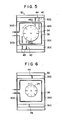
- the hot air to be blown from holes 26 and 28 is biased to the upstream side of the hot air flow. More specifically, as shown in Fig. 2, the amount of hot air discharged from some holes 26 in region B located at the downstream side of the hot air flow in storing chamber 32 is larger than that discharged from some other holes 26 in region A at the upstream side of the hot air flow. Similarly, the amount of hot air discharged from some holes 28 in region D located at the downstream side of the hot air flow in storing chamber 32 is larger than that discharged from some other holes 28 in region C at the upstream side. Therefore, in order to prevent the unbalance of the amount in discharged hot air, according to this embodiment, upper and lower airflow-directing mechanisms 40 and 42 are provided in chamber 32 so as to face regions A and C, respectively.
- upper airflow-directing mechanism 40 has a pair of first airflow-directing plates 44 and a pair of second airflow-directing plates 46a and 46b.
- First plates 44 have a triangular shape, are fixed to upper plate 30b of cover 30, and extend in the vertical direction.
- Second plates 46a and 46b are perpendicularly fixed to bottom plate 30a of cover 30 and located between the outer periphery of fan 34 and heater 36. Plates 46a and 46b have a rectangular shape. Plate 46a is shorter than plate 46b. Plates 46a and 46b are arranged parallel to each other and extend from the regions close to the lower ends of first airflow-directing plates 44 toward the rotational center of fan 34.
- lower airflow-directing mechanism 42 has a pair of first airflow-directing plates 48 and a pair of second airflow-directing plates 50a and 50b.
- First plates 48 and second plates 50a and 50b are point-symmetrical to first plates 44 and second plates 46a and 46b, respectively, with respect to the rotational center of fan 34.
- first plates 48 are fixed to lower plate 30c of cover 30 and extend in the vertical direction
- second plate 50a and 50b are fixed to bottom plate 30a of cover 30 and located between the outer periphery of fan 34 and heater 36.
- first and second airflow-directing mechanisms 40 and 42 are set as follows so as to provide a good airflow-directing effect
- diameter a of fan 34 is set in a range of about 1/2 to 1/3 width b of heating chamber 14. In other words, assuming that width b is 300 mm, diameter a of fan 34 is 130 mm.
- distance c between second airflow-directing plate 46b and the outer periphery of fan 34 is set to be about 1/10 to 1/20 diameter a of fan 34 and is, in this embodiment, 9 mm.
- Distance e between second airflow-directing plate 46a and the outer periphery of fan 34 is set to be about 1/5 to 1/10 diameter a of fan 34 and is, in this embodiment, 19 mm.
- Distance d between plates 46a and 46b is set in a range of about 1/3 to 1/6 diameter a of fan 34 and is, in this embodiment, 33 mm.
- Distance between first airflow-directing plates 44 corresponds to distance d .
- Distance f between second airflow-directing plates 46a and 46b, and heater 36 is set in a range of about 1/2 to 1/10 diameter g of heater 36.
- a general heater has diameter g of about 7 mm and hence distance f is set to 1 mm.
- Width h of the regions, wherein upper and lower discharge holes 26 and 28 are formed, is set to 2/3 or more of width b of heating chamber 14 (h ⁇ 200 mm). Holes 26 and 28 are uniformly distributed in the right and left portions of heating chamber 14 so that the hot air uniformly reaches the entire area of heating chamber 14.
- the airflow-directing plates of lower airflow-directing mechanism 42 have sizes similar to those of upper airflow-directing mechanism 40 and a description thereof is omitted.
- reference numeral 54 denotes a motor.
- Rotation shaft 54a of motor 54 extends into heating chamber 14 through bottom plate 12b of casing 12.
- a turntable (not shown) is placed in engagement with rotation shaft 54a within heating chamber 14 such that it may be rotated by motor 54.
- the cooker is also further provided with a magnetron (not shown) and can be used as a microwave oven.
- heating chamber 14 When a large amount of food is heated and cooked simultaneously, upper and lower cooking trays 22a and 22b placing food 52 thereon are set in heating chamber 14 through inlet/outlet port 16. After door 18 is closed, an operating section (not shown) is operated to energize motor 38 and heater 36. When fan 34 is rotated counterclockwise by motor 38, the air between trays 22a and 22b in chamber 14 is drawn into storing chamber 32 through suction holes 24. The sucked air flows to the periphery of fan 34, and makes a counterclockwise whirl around fan 34. At the same time, the air is heated by heater 36.
- the hot air abuts against upper and lower plates 30b and 30c of cover 30 and directed toward rear plate 12c of inner casing 12.
- the hot air is discharged from discharge holes 26 and 28 into heating chamber 14.
- the hot air from holes 26 is blown into a space between top plate 12a of casing 12 and upper cooking tray 22a, and the hot air from holes 28 is blown into a space between bottom plate 12b of casing 12 and lower cooking tray 22b.
- part of the hot air is prevented by airflow-directing plates 44, 46a and 46b of upper airflow-direction mechanism 40 from flowing along the rotating direction of fan 34 and guided to a region opposing upstream-side region A of discharge holes 26.
- the hot air is then directed toward rear plate 12c by upper plate 30b of cover 30 and discharged to heating chamber 14 through discharge holes 26 at upstream-side region A.
- the remaining hot air is discharged from holes 26 located at downstream-side region B.
- the amount of hot air discharged from discharge holes 26 and 28 located at upstream-side regions A and C is increased because of the straightening function of upper and lower airflow-directing mechanisms 40 and 42, and becomes equal to that discharged from holes 26 and 28 located at downstream-side regions B and D.
- imbalance in amount of discharged hot air between the holes in the upstream- and downstream-side regions is eliminated, and hot air can be uniformly supplied to the entire portion in the heating chamber.
- a hot air does not locally blow against part of food in the heating chamber, and nonuniform heating and cooking caused by the nonuniform hot air amount can be prevented.
- each airflow-directing mechanism has the second airflow-directing plates that extend to the regions close to the outer periphery of fan 34. Therefor, the hot air can be guided to the discharge holes located in the upstream-side region immediately after fan rotation is started.
- the second airflow-directing plates When distance f between the second airflow-directing plate and heater 36 exceeds 1/2 diameter g of heater 36, hot air leaks from a gap between the airflow-directing plates and heater 36, and the blow amount of air straightened by the airflow-directing mechanism is decreased. As a result, nonuniform heating occurs.
- distance f is less than 1/10 diameter g , the second airflow-directing plates may unpreferably contact heater 36 by vibration during operation of the cooker of impact when the cooker is being moved.
- each airflow-directing mechanism has a pair of second airflow-directing plates.
- the inner one i.e., the smaller one of the second airflow-directing plates can be omitted.
- Second airflow-directing plates 46a and 46b, or 50a and 50b can be arranged in the vertical direction as shown in Fig. 5.
- the dimensional relationship among the width of heating chamber 14, the diameter of fan 34, the distance between fan 34 and the airflow-directing plates, and the distance between the second airflow-directing plates and heater 36; and the sizes and mounting positions of the first and second airflow-directing plates are set so as to obtain hot air blowing characteristics to effectively decrease nonuniform heating.
- each airflow-directing mechanism can be constructed by only first airflow-directing plates.
- the number of the first airflow-directing plates is increased/decreased as needed, and the sizes and mounting positions thereof are properly set.
- first airflow-directing plate 44 of upper airflow-directing mechanism 40 and airflow-directing plate 48 of lower airflow-directing mechanism 42 are point-symmetrically arranged with respect to the rotational center of fan 34, irrespective of the number of the first airflow-directing plates.
- the hot air blow amount can be finely adjusted.
- upper airflow-directing mechanism 40 has a plurality of first airflow-directing plates fixed to upper plate 30b of cover 30. These plates 44 are separated from each other at the same intervals along the horizontal direction and extend in the vertical direction. The lengths of respective airflow-directing plates 44 are set such that a line connecting the lower ends of plates 44 coincides with diagonal line a of plate 30b. This increases straightening effect in a region at the upstream-side of the hot air flow.
- Airflow-directing mechanism 40 has second airflow-directing plate 46 located in the upper region of storing chamber 32. Plate 46 extends substantially horizontally from side plate 30d of cover 30, located at the downstream side of the hot air flow, to the substantially central portion of storing chamber 32.
- Plate 46 is positioned between fan 34 and heater 36.
- lower airflow-directing mechanism 42 has a plurality of first airflow-directing plates 48 and second airflow-directing plate 50 and is point-symmetrical with mechanism 40 with respect to the rotational center of fan 34.
- airflow-directing mechanisms 40 and 42 have a plurality of airflow-directing plates 44 and 48 fixed to the inclined plates of cover 30, i.e., upper and lower plates 30b and 30c and extending in the vertical direction, respectively.
- Straightening plate 44a (48a) horizontally extends from each airflow-directing plate.
- Each plate 44a or 48a is formed by cutting part of the corresponding wind-directing plate and bending the cut portion upright, or fixing a separate plate on the corresponding airflow-directing plate by spot welding or the like.
- plate 44a is inclined at angle ⁇ 2 (the same as or smaller than angle ⁇ 1) with respect to the horizontal plane.
- Plate 48a is also inclined at a predetermined angle with respect to the horizontal plane.
- the air supplied from fan 34 is straightened by airflow-directing plates 44 and 48 and partially directed by straightening plates 44a and 48a in a direction different from that of the air directed by inclined plates 30b and 30c of cover 30.
- the hot air is sufficiently dispersed and uniformly discharged in heating chamber 14.
- a plate for fixing the cover defining the storing chamber is not limited to the rear plate of the inner casing, but can be another side plate.
Landscapes
- Engineering & Computer Science (AREA)
- Chemical & Material Sciences (AREA)
- Combustion & Propulsion (AREA)
- Mechanical Engineering (AREA)
- General Engineering & Computer Science (AREA)
- Food Science & Technology (AREA)
- Baking, Grill, Roasting (AREA)
- Cookers (AREA)
Applications Claiming Priority (4)
| Application Number | Priority Date | Filing Date | Title |
|---|---|---|---|
| JP111110/86 | 1986-05-15 | ||
| JP61111110A JPH07111256B2 (ja) | 1986-05-15 | 1986-05-15 | 熱風循環式調理器 |
| JP147540/86 | 1986-06-24 | ||
| JP61147540A JPH06103099B2 (ja) | 1986-06-24 | 1986-06-24 | 熱風循環式調理器 |
Publications (3)
| Publication Number | Publication Date |
|---|---|
| EP0245618A2 true EP0245618A2 (de) | 1987-11-19 |
| EP0245618A3 EP0245618A3 (en) | 1989-02-22 |
| EP0245618B1 EP0245618B1 (de) | 1991-05-15 |
Family
ID=26450580
Family Applications (1)
| Application Number | Title | Priority Date | Filing Date |
|---|---|---|---|
| EP87103969A Expired - Lifetime EP0245618B1 (de) | 1986-05-15 | 1987-03-18 | Umluftherd |
Country Status (6)
| Country | Link |
|---|---|
| US (1) | US4870254A (de) |
| EP (1) | EP0245618B1 (de) |
| KR (1) | KR910001698B1 (de) |
| AU (1) | AU575743B2 (de) |
| CA (1) | CA1280904C (de) |
| DE (1) | DE3770045D1 (de) |
Cited By (9)
| Publication number | Priority date | Publication date | Assignee | Title |
|---|---|---|---|---|
| EP0409324A1 (de) * | 1989-07-18 | 1991-01-23 | Whirlpool International B.V. | Heissluftofen |
| EP0419213A3 (en) * | 1989-09-22 | 1992-06-10 | Patentsmith Ii, Inc. | Balanced air return convection oven |
| US5423248A (en) * | 1989-09-22 | 1995-06-13 | Patentsmith Corporation | Air circulator for impingement heat transfer apparatus |
| DE20309268U1 (de) * | 2003-06-12 | 2004-06-09 | Rational Ag | Gargeräte mit Luftleitgliedern |
| EP1992879A1 (de) * | 2007-05-16 | 2008-11-19 | Electrolux Home Products Corporation N.V. | Backofen, insbesondere Haushaltsbackofen |
| EP1970635A3 (de) * | 2008-06-26 | 2009-02-18 | V-Zug AG | Heissluft-Backofen mit Umlenkblechen |
| CN101501434B (zh) * | 2006-08-11 | 2012-10-10 | 艾森曼股份公司 | 热风炉模块和热风炉 |
| ES2455719A1 (es) * | 2012-10-16 | 2014-04-16 | BSH Electrodomésticos España S.A. | Aparato de cocción con una calefacción por aire circulante |
| EP3620722A1 (de) * | 2018-09-04 | 2020-03-11 | Whirlpool Corporation | Umluftofen mit gasbeheizung |
Families Citing this family (22)
| Publication number | Priority date | Publication date | Assignee | Title |
|---|---|---|---|---|
| IT1227212B (it) * | 1988-09-23 | 1991-03-27 | Eurodomestici Ind Riunite | Forno elettrico, a doppia camera ad irraggiamento uniforme, particolarmente per la preparazione di torte e dolci in generale |
| IT1258073B (it) * | 1992-04-29 | 1996-02-20 | Zanussi Elettromecc | Dispositivo di misura dell'umidita' per forni, in particolare forni dicottura di alimenti |
| US5285719A (en) * | 1992-09-11 | 1994-02-15 | Gas Research Institute | Rapid frozen food thawing system |
| US5336867A (en) * | 1993-12-13 | 1994-08-09 | General Electric Company | Convection oven tapered air heating chamber |
| US5801362A (en) * | 1994-01-14 | 1998-09-01 | Hudson Standard Corporation | Portable electric oven with fan and motor arrangement for improved heated air flow and motor cooling |
| US5588353A (en) * | 1995-07-18 | 1996-12-31 | Appliance Development Corp. | Automatic bread-making apparatus |
| US5584233A (en) * | 1995-07-18 | 1996-12-17 | Appliance Development Corp. | Automatic bread-making apparatus |
| US5676044A (en) * | 1996-01-03 | 1997-10-14 | Lara, Jr.; George A. | Rotary air impingement oven |
| US5601070A (en) * | 1996-06-17 | 1997-02-11 | Middleby Marshall, Inc. | Convection oven |
| US6069344A (en) * | 1999-01-27 | 2000-05-30 | Hp Intellectual Corp. | Convection feature for use in ovens |
| FR2839546B1 (fr) * | 2002-05-07 | 2006-09-22 | Premark Feg Llc | Four pour la cuisson d'aliments |
| US7119306B2 (en) * | 2003-01-09 | 2006-10-10 | Premark Feg L.L.C. | Food thawing cabinet and related methods |
| JP3701295B2 (ja) * | 2003-05-15 | 2005-09-28 | シャープ株式会社 | 加熱調理器 |
| US6802247B1 (en) * | 2004-02-02 | 2004-10-12 | Ming-Tsung Lee | Electric oven |
| WO2005092400A1 (en) * | 2004-03-26 | 2005-10-06 | C.T.R. Consultoria Tecnica E Representacoes, Lda. | Device for the evaporation of volatile substances, in particular of aromatics and/or insecticides |
| CN101873732A (zh) * | 2004-12-14 | 2010-10-27 | 印欧第斯公司 | 冲击/对流/微波烤箱和方法 |
| US10890336B2 (en) | 2015-06-08 | 2021-01-12 | Alto-Shaam, Inc. | Thermal management system for multizone oven |
| US9677774B2 (en) | 2015-06-08 | 2017-06-13 | Alto-Shaam, Inc. | Multi-zone oven with variable cavity sizes |
| US10337745B2 (en) | 2015-06-08 | 2019-07-02 | Alto-Shaam, Inc. | Convection oven |
| US10088172B2 (en) | 2016-07-29 | 2018-10-02 | Alto-Shaam, Inc. | Oven using structured air |
| US9879865B2 (en) | 2015-06-08 | 2018-01-30 | Alto-Shaam, Inc. | Cooking oven |
| CN105341013A (zh) * | 2015-12-14 | 2016-02-24 | 新麦机械(无锡)有限公司 | 一种烤炉的导风装置 |
Family Cites Families (16)
| Publication number | Priority date | Publication date | Assignee | Title |
|---|---|---|---|---|
| US2582887A (en) * | 1942-03-17 | 1952-01-15 | Sanford | Cooking stove |
| US3081392A (en) * | 1955-02-24 | 1963-03-12 | Tappan Co | High-frequency oven |
| US2906620A (en) * | 1956-02-21 | 1959-09-29 | Burger Eisenwerke Gmbh | Method of de-freezing and heating deep-frozen foods |
| US3324844A (en) * | 1965-11-09 | 1967-06-13 | Vulcan Hart Corp | Heat distribution system for gas-fired ovens |
| CH573574A5 (de) * | 1972-11-24 | 1976-03-15 | Siemens Elektrogeraete Gmbh | |
| DE2339446C3 (de) * | 1973-08-03 | 1978-03-02 | Bosch-Siemens Hausgeraete Gmbh, 7000 Stuttgart | Umluftofen zum Garen von Lebensmitteln |
| DE2557867C3 (de) * | 1975-12-22 | 1979-11-08 | Bosch-Siemens Hausgeraete Gmbh, 7000 Stuttgart | Umluftofen |
| DE2657267A1 (de) * | 1976-12-17 | 1978-06-22 | British Gas Corp | Ofen mit zwangsumlauf |
| JPS53136572A (en) * | 1977-05-02 | 1978-11-29 | Matsushita Electric Industrial Co Ltd | Electric oven |
| AU524652B2 (en) * | 1977-11-23 | 1982-09-30 | Email Limited | Forced air oven |
| WO1981000341A1 (en) * | 1979-07-27 | 1981-02-19 | Matsushita Electric Industrial Co Ltd | Heating cooking device |
| AU8855482A (en) * | 1981-10-02 | 1983-04-14 | Gas & Fuel Corp. of Victoria | Oven distributer unit |
| JPS5892731A (ja) * | 1981-11-25 | 1983-06-02 | Matsushita Electric Ind Co Ltd | 強制熱風循環式ガスオ−ブン |
| JPS58106331A (ja) * | 1981-12-17 | 1983-06-24 | Matsushita Electric Ind Co Ltd | 複合加熱調理器 |
| AU547607B2 (en) * | 1982-04-14 | 1985-10-24 | Matsushita Electric Industrial Co., Ltd. | Hot air circulation type cooking device |
| FR2559240B1 (fr) * | 1984-02-03 | 1986-05-30 | Seb Sa | Appareil de cuisson portatif comportant une enceinte et une plaque de cuisson |
-
1987
- 1987-03-16 AU AU70054/87A patent/AU575743B2/en not_active Ceased
- 1987-03-18 DE DE8787103969T patent/DE3770045D1/de not_active Expired - Lifetime
- 1987-03-18 EP EP87103969A patent/EP0245618B1/de not_active Expired - Lifetime
- 1987-03-19 CA CA000532519A patent/CA1280904C/en not_active Expired - Lifetime
- 1987-05-15 KR KR1019870004813A patent/KR910001698B1/ko not_active Expired
-
1988
- 1988-08-23 US US07/235,768 patent/US4870254A/en not_active Expired - Lifetime
Cited By (11)
| Publication number | Priority date | Publication date | Assignee | Title |
|---|---|---|---|---|
| EP0409324A1 (de) * | 1989-07-18 | 1991-01-23 | Whirlpool International B.V. | Heissluftofen |
| EP0419213A3 (en) * | 1989-09-22 | 1992-06-10 | Patentsmith Ii, Inc. | Balanced air return convection oven |
| US5423248A (en) * | 1989-09-22 | 1995-06-13 | Patentsmith Corporation | Air circulator for impingement heat transfer apparatus |
| US5683240A (en) * | 1989-09-22 | 1997-11-04 | Patentsmith Technology, Ltd. | Balanced air return convection oven |
| DE20309268U1 (de) * | 2003-06-12 | 2004-06-09 | Rational Ag | Gargeräte mit Luftleitgliedern |
| CN101501434B (zh) * | 2006-08-11 | 2012-10-10 | 艾森曼股份公司 | 热风炉模块和热风炉 |
| EP1992879A1 (de) * | 2007-05-16 | 2008-11-19 | Electrolux Home Products Corporation N.V. | Backofen, insbesondere Haushaltsbackofen |
| EP1970635A3 (de) * | 2008-06-26 | 2009-02-18 | V-Zug AG | Heissluft-Backofen mit Umlenkblechen |
| ES2455719A1 (es) * | 2012-10-16 | 2014-04-16 | BSH Electrodomésticos España S.A. | Aparato de cocción con una calefacción por aire circulante |
| EP3620722A1 (de) * | 2018-09-04 | 2020-03-11 | Whirlpool Corporation | Umluftofen mit gasbeheizung |
| US11454403B2 (en) | 2018-09-04 | 2022-09-27 | Whirlpool Corporation | Double oven gas with fan |
Also Published As
| Publication number | Publication date |
|---|---|
| KR880013517A (ko) | 1988-12-21 |
| KR910001698B1 (ko) | 1991-03-18 |
| CA1280904C (en) | 1991-03-05 |
| EP0245618A3 (en) | 1989-02-22 |
| DE3770045D1 (de) | 1991-06-20 |
| US4870254A (en) | 1989-09-26 |
| EP0245618B1 (de) | 1991-05-15 |
| AU7005487A (en) | 1987-11-19 |
| AU575743B2 (en) | 1988-08-04 |
Similar Documents
| Publication | Publication Date | Title |
|---|---|---|
| EP0245618A2 (de) | Umluftherd | |
| US4780596A (en) | Hot-air circulation cooking oven | |
| US5601070A (en) | Convection oven | |
| EP0105931B1 (de) | Kochvorrichtung mit heissluftumwälzung | |
| EP0429822B1 (de) | Kombinierter Mikrowellen- und gezwungener Konvektionsofen | |
| US4481396A (en) | Combination microwave and convection oven | |
| US3583306A (en) | Evacuating means | |
| AU635560B2 (en) | Balanced air return convection oven | |
| US4786774A (en) | Combination compact microwave oven and ventilator system | |
| KR19990022382A (ko) | 제트 충돌 배취형 오븐 | |
| KR900005123A (ko) | 겸용 조리 오븐 | |
| CA1249638A (en) | Microwave oven with two cooling fans | |
| JPS59164826A (ja) | 食品およびスパイスの熱処理装置 | |
| US5193520A (en) | Cooking apparatus | |
| US4539469A (en) | Oven control circuitry cooling system for a double-stack food preparation oven arrangement | |
| CN113143053A (zh) | 烹饪设备 | |
| EP0089762A1 (de) | Ventilator-Speicher-Anordnung | |
| EP1478888B1 (de) | Ofen mit zwangsluftumwälzung | |
| JP3209963B2 (ja) | 電子レンジ | |
| US7044122B2 (en) | Direct convection oven | |
| JP2728314B2 (ja) | 空気処理装置およびその流量を減らす方法 | |
| US4549055A (en) | Ventilating means for cooking apparatus | |
| EP0152571B1 (de) | Ofen mit erzwungener Konvektion | |
| EP0611524A1 (de) | Umluft-Kochofen | |
| EP1560464B1 (de) | Wandmontierter Mikrowellenofen |
Legal Events
| Date | Code | Title | Description |
|---|---|---|---|
| PUAI | Public reference made under article 153(3) epc to a published international application that has entered the european phase |
Free format text: ORIGINAL CODE: 0009012 |
|
| 17P | Request for examination filed |
Effective date: 19870415 |
|
| AK | Designated contracting states |
Kind code of ref document: A2 Designated state(s): DE FR GB |
|
| PUAL | Search report despatched |
Free format text: ORIGINAL CODE: 0009013 |
|
| AK | Designated contracting states |
Kind code of ref document: A3 Designated state(s): DE FR GB |
|
| 17Q | First examination report despatched |
Effective date: 19900312 |
|
| GRAA | (expected) grant |
Free format text: ORIGINAL CODE: 0009210 |
|
| AK | Designated contracting states |
Kind code of ref document: B1 Designated state(s): DE FR GB |
|
| REF | Corresponds to: |
Ref document number: 3770045 Country of ref document: DE Date of ref document: 19910620 |
|
| ET | Fr: translation filed | ||
| PLBE | No opposition filed within time limit |
Free format text: ORIGINAL CODE: 0009261 |
|
| STAA | Information on the status of an ep patent application or granted ep patent |
Free format text: STATUS: NO OPPOSITION FILED WITHIN TIME LIMIT |
|
| 26N | No opposition filed | ||
| REG | Reference to a national code |
Ref country code: GB Ref legal event code: 746 Effective date: 19981008 |
|
| REG | Reference to a national code |
Ref country code: FR Ref legal event code: D6 |
|
| REG | Reference to a national code |
Ref country code: GB Ref legal event code: IF02 |
|
| PGFP | Annual fee paid to national office [announced via postgrant information from national office to epo] |
Ref country code: FR Payment date: 20030310 Year of fee payment: 17 |
|
| PGFP | Annual fee paid to national office [announced via postgrant information from national office to epo] |
Ref country code: GB Payment date: 20030312 Year of fee payment: 17 |
|
| PGFP | Annual fee paid to national office [announced via postgrant information from national office to epo] |
Ref country code: DE Payment date: 20030327 Year of fee payment: 17 |
|
| PG25 | Lapsed in a contracting state [announced via postgrant information from national office to epo] |
Ref country code: GB Free format text: LAPSE BECAUSE OF NON-PAYMENT OF DUE FEES Effective date: 20040318 |
|
| PG25 | Lapsed in a contracting state [announced via postgrant information from national office to epo] |
Ref country code: DE Free format text: LAPSE BECAUSE OF NON-PAYMENT OF DUE FEES Effective date: 20041001 |
|
| GBPC | Gb: european patent ceased through non-payment of renewal fee |
Effective date: 20040318 |
|
| PG25 | Lapsed in a contracting state [announced via postgrant information from national office to epo] |
Ref country code: FR Free format text: LAPSE BECAUSE OF NON-PAYMENT OF DUE FEES Effective date: 20041130 |
|
| REG | Reference to a national code |
Ref country code: FR Ref legal event code: ST |