EP0244885A2 - Hinteres Endstück für ein Fahrrad - Google Patents
Hinteres Endstück für ein Fahrrad Download PDFInfo
- Publication number
- EP0244885A2 EP0244885A2 EP87200507A EP87200507A EP0244885A2 EP 0244885 A2 EP0244885 A2 EP 0244885A2 EP 87200507 A EP87200507 A EP 87200507A EP 87200507 A EP87200507 A EP 87200507A EP 0244885 A2 EP0244885 A2 EP 0244885A2
- Authority
- EP
- European Patent Office
- Prior art keywords
- wheel
- main body
- fork end
- mounting member
- rear fork
- Prior art date
- Legal status (The legal status is an assumption and is not a legal conclusion. Google has not performed a legal analysis and makes no representation as to the accuracy of the status listed.)
- Granted
Links
Images
Classifications
-
- B—PERFORMING OPERATIONS; TRANSPORTING
- B62—LAND VEHICLES FOR TRAVELLING OTHERWISE THAN ON RAILS
- B62K—CYCLES; CYCLE FRAMES; CYCLE STEERING DEVICES; RIDER-OPERATED TERMINAL CONTROLS SPECIALLY ADAPTED FOR CYCLES; CYCLE AXLE SUSPENSIONS; CYCLE SIDECARS, FORECARS, OR THE LIKE
- B62K25/00—Axle suspensions
- B62K25/02—Axle suspensions for mounting axles rigidly on cycle frame or fork, e.g. adjustably
-
- B—PERFORMING OPERATIONS; TRANSPORTING
- B62—LAND VEHICLES FOR TRAVELLING OTHERWISE THAN ON RAILS
- B62K—CYCLES; CYCLE FRAMES; CYCLE STEERING DEVICES; RIDER-OPERATED TERMINAL CONTROLS SPECIALLY ADAPTED FOR CYCLES; CYCLE AXLE SUSPENSIONS; CYCLE SIDECARS, FORECARS, OR THE LIKE
- B62K19/00—Cycle frames
- B62K19/30—Frame parts shaped to receive other cycle parts or accessories
Definitions
- This invention relates to a bicycle rear fork end, for rear-wheel mounting, particularly for racing bicycles.
- a bicycle frame For mounting a rear wheel, a bicycle frame has, on each side of the wheel, a pair of tubes which extend towards each other from the ends of the seat-bearing upright tube, to the position of the hub, and are there connected to a fork end connecting both tubes together and having a seat for the wheel hub.
- the conventional rear-wheel fork end is a cast plate having two projections adapted to be fitted to the ends of the above pair of tubes, which tubes are then squeezed and welded thereon.
- the plate has a seat for one end of the hub, in the form of a chain-tightening slot extending lengthwise to the bicycle frame, so that the axle distance between the hub and the pedals can be changed, and so that possible misalignments of the wheel with respect to the midplane of the frame can be compensated.
- the hub is then locked in the desired position by means of a fastener such as a wing nut, or more modernly, by means of a toggle clamp.
- Such chain-tightening slot in prior fork ends usually opened rearwardly, but nowadays it always opens forwardly, so that the wheel can be quickly changed.
- a threaded pin is provided to adjustably project from the bottom of the mounting slot, to provide an abutment, to be adjusted once for all during line-up of the bicycle.
- wheel rim in bicycles having a fork end of the prior art i.e. with forward opening slot
- This invention now has the object of providing a bicycle fork end for rear-wheel mounting, which avoids the above drawbacks, and more particularly which allows an accurate adjustment to be made in the position of the hub, once for all during bicycle line-up, so that wheel changing requires a shorter time.
- Another object is to provide a fork end where all liability to hub slipping is avoided, even when the hub is insufficiently tightened on the fork end.
- Another object is to provide a fork end such that it can be adapted, without forcing, to frames having differently angled rear tubes, without a need for providing differently shaped fork ends for different frames, with ensuing advantages both in stock count reduction and in decrease of the expense for moulds.
- a bicycle rear fork end for rear-wheel mounting particularly for racing bicycles, comprising a main body having joint means for connection to a pair of rear tubes of a bicycle frame, and a wheel-mounting member having a mounting slot for one end of a wheel hub, the main body and the wheel-mounting member being mutually connected by longitudinally adjustable fastening means, whereby the longitudinal position of the wheel-mounting member with respect to the main body can be adjusted.
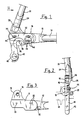
- a fork end for rear-wheel mounting has a main body formed as a steel plate 10, preferably obtained by precision casting, forwardly ending in a socket 12 for fitting and welding of a lower rear tube 14 of a bicycle (not shown), and having a thickened upper lug 16, provided with a bore 18.
- the thickness of plate 10 is half the thickness of lug 16.
- Plate 10 also has three threaded bores 20, arranged in triangle.
- a bridge 22 for the cable of the gear shift is preferably obtained integrally near socket 12.
- the fork end of the invention further includes a socket 24 for the upper rear tube 26 of the bicycle, provided with an extension 28 having an integral cross pin 30, the pin being housed in bore 18 in plate 10, where it is welded or braised in a desired inclination.
- the fork end further comprises a wheel-mounting member 32, which also is made as a preferably precision-cast steel plate, with three slots 34 arranged in a triangle identically to the bores in the main body 10, with countersunk outside edges, and with a downwardly open slot 36 for mounting a wheel hub 38 (shown in dashed lines).
- Wheel-mounting member 32 also preferably comprises (only for the right-hand fork end, where a gear shift is provided) a spur 40 with a hole 42 for housing a gear shift shunt (not shown), as known per se.
- the thickness of the portion of the wheel-mounting member where the slots are provided is half the thickness of spur 40.
- Wheel-mounting member 32 is fitted to main body 10 with slots 34 aligned with threaded bores 20, and is fastened with respective hexagonal-head screws 44, in a desired longitudinal position, to be adjusted during line-up of the bicycle. Due to the corresponding thickness reduction both in main body 10 and in wheel-mounting member 32, the assembly has levelled opposite surfaces, so that the various portions of hub 38 can be properly supported.
- the longitudinal position of the hub axis can be accurately adjusted once for all during line-up of the bicycle.
- the hub is then inserted from beneath into mounting slot 36, in a direction tangential to the chain, and takes an exactly defined position, not requiring any further fine adjustment even when the wheel is changed, e. g. during a race, with great advantage in change speed, in case of wheel failure.
- the hub after being locked in the required position, even in case of clamp loosening, will not slip under the chain pull, being held by positive abutment against the forward side of the slot.
- Another advantage of the tangential insertion of the hub into the mounting slot is that removing (or inserting) the wheel from or into the bicycle frame does not require any approach of the wheel to the seat-bearing upright tube, as with prior fork ends.
- the wheel rim can be designed to be a a distance of a few millimeters from the upright tube, when in operating condition, rather than at a few centimeters, as in the prior art, and the frame can therefore be more compact.
- rear-wheel fork ends can be assembled for arbitrarily angled rear tubes of the frame, from a single set of parts, rather than pro viding a different fork end for each frame. The stock count is thereby reduced.
- the number and arrangement of threaded bores in the main body may be changed, or the slots may be provided in the main body, and the threaded bores in the wheel-mounting member, and generally other known fastening means between the main body and the wheel-mounting member can be used, such as slides and the like.
- the downward direction of opening of the wheel-mounting slot although preferred for the reasons stated, is, however, unessential within the idea of the invention, because even a differently directed opening would still impart the fork end the basic advantage of the accuracy of adjustment, due to which further adjustments during wheel change are avoided.
- the feature of an articulated upper socket can be dispensed with, whenever the circumstances of application of the invention do not require adaptability to different tube inclinations, the main body and the upper socket being then cast integrally.
Landscapes
- Engineering & Computer Science (AREA)
- Mechanical Engineering (AREA)
- Steering Devices For Bicycles And Motorcycles (AREA)
- Motorcycle And Bicycle Frame (AREA)
Applications Claiming Priority (2)
| Application Number | Priority Date | Filing Date | Title |
|---|---|---|---|
| IT5318986U | 1986-03-26 | ||
| IT5318986U IT207484Z2 (it) | 1986-03-26 | 1986-03-26 | Forcellino per ruota posteriore per biciclette particolarmente da competizione |
Publications (3)
| Publication Number | Publication Date |
|---|---|
| EP0244885A2 true EP0244885A2 (de) | 1987-11-11 |
| EP0244885A3 EP0244885A3 (en) | 1988-07-27 |
| EP0244885B1 EP0244885B1 (de) | 1991-06-05 |
Family
ID=11280686
Family Applications (1)
| Application Number | Title | Priority Date | Filing Date |
|---|---|---|---|
| EP19870200507 Expired EP0244885B1 (de) | 1986-03-26 | 1987-03-19 | Hinteres Endstück für ein Fahrrad |
Country Status (3)
| Country | Link |
|---|---|
| EP (1) | EP0244885B1 (de) |
| DE (1) | DE3770519D1 (de) |
| IT (1) | IT207484Z2 (de) |
Cited By (13)
| Publication number | Priority date | Publication date | Assignee | Title |
|---|---|---|---|---|
| EP0421257A1 (de) * | 1989-10-02 | 1991-04-10 | Cannondale Corporation | Auswechselbarer Umwerfbügel |
| DE10157811C1 (de) * | 2001-11-27 | 2003-05-08 | Jochen Kleinebenne | Fahrradrahmen |
| NL1023459C2 (nl) * | 2003-05-19 | 2004-11-22 | Batavus Bv | Achtervorkpadden met opvulstukken. |
| ES2255449A1 (es) * | 2004-12-15 | 2006-06-16 | Orbea S. Coop. Ltda. | Pata trasera para bicicleta. |
| WO2010102349A1 (en) * | 2009-03-13 | 2010-09-16 | Alan Fetterplace | Fork assemblies |
| US20110316250A1 (en) * | 2010-06-23 | 2011-12-29 | Lumpkin Wayne R | Bicycle Sliding Dropout |
| WO2012145831A1 (en) * | 2011-04-26 | 2012-11-01 | Paul Harris | Replaceable and open-able dropout system enabling adjustable width and height |
| US8424894B2 (en) * | 2009-08-21 | 2013-04-23 | Speedhound Design Bureau, Llc | Bicycle frame dropouts and methods |
| JP2013252784A (ja) * | 2012-06-06 | 2013-12-19 | Bridgestone Cycle Co | リヤエンドおよびそれを用いた自転車 |
| EP2842859A1 (de) * | 2013-08-28 | 2015-03-04 | Winora-Staiger GmbH | Fahrradrahmen aus faserverstärktem Werkstoff mit Adapterplatten für das Hinterrad |
| KR20180026171A (ko) * | 2016-09-02 | 2018-03-12 | 현대자동차주식회사 | 드롭 아웃을 갖는 자전거 프레임구조 |
| EP3539856A1 (de) * | 2018-03-14 | 2019-09-18 | Canyon Bicycles GmbH | Aufnahmeeinrichtung für eine fahrrad-hinterradachse |
| IT202300003714A1 (it) * | 2023-03-01 | 2024-09-01 | Tra Fi Me S P A | Telaio per biciclette |
Family Cites Families (4)
| Publication number | Priority date | Publication date | Assignee | Title |
|---|---|---|---|---|
| JPS5235807Y2 (de) * | 1973-12-29 | 1977-08-15 | ||
| FR2405174A1 (fr) * | 1977-10-04 | 1979-05-04 | Motobecane Ateliers | Dispositif de reglage de la position d'un axe de roue d'un cycle par rapport au cadre |
| FR2483350A1 (fr) * | 1980-05-27 | 1981-12-04 | Levet Guy | Dispositif de reglage de la position longitudinale de l'axe de la roue arriere des bicyclettes et vehicules similaires, sur les pattes de cadre, et les pattes ainsi equipees |
| FR2490176A1 (fr) * | 1980-09-16 | 1982-03-19 | Levet Guy | Patte de cadre de bicyclettes et vehicules similaires, avec dispositif de reglage de la position longitudinale de l'axe de la roue arriere |
-
1986
- 1986-03-26 IT IT5318986U patent/IT207484Z2/it active
-
1987
- 1987-03-19 EP EP19870200507 patent/EP0244885B1/de not_active Expired
- 1987-03-19 DE DE8787200507T patent/DE3770519D1/de not_active Expired - Fee Related
Cited By (18)
| Publication number | Priority date | Publication date | Assignee | Title |
|---|---|---|---|---|
| EP0421257A1 (de) * | 1989-10-02 | 1991-04-10 | Cannondale Corporation | Auswechselbarer Umwerfbügel |
| DE10157811C1 (de) * | 2001-11-27 | 2003-05-08 | Jochen Kleinebenne | Fahrradrahmen |
| NL1023459C2 (nl) * | 2003-05-19 | 2004-11-22 | Batavus Bv | Achtervorkpadden met opvulstukken. |
| EP1479602A3 (de) * | 2003-05-19 | 2007-11-28 | Batavus B.V. | Hinteres Endstück mit Einsatzteilen |
| ES2255449A1 (es) * | 2004-12-15 | 2006-06-16 | Orbea S. Coop. Ltda. | Pata trasera para bicicleta. |
| ES2255449B1 (es) * | 2004-12-15 | 2007-12-01 | Orbea S. Coop. Ltda. | Pata trasera para bicicleta. |
| WO2010102349A1 (en) * | 2009-03-13 | 2010-09-16 | Alan Fetterplace | Fork assemblies |
| US8424894B2 (en) * | 2009-08-21 | 2013-04-23 | Speedhound Design Bureau, Llc | Bicycle frame dropouts and methods |
| US8740239B2 (en) * | 2010-06-23 | 2014-06-03 | Alto Designs, Llc | Bicycle sliding dropout |
| US20110316250A1 (en) * | 2010-06-23 | 2011-12-29 | Lumpkin Wayne R | Bicycle Sliding Dropout |
| WO2012145831A1 (en) * | 2011-04-26 | 2012-11-01 | Paul Harris | Replaceable and open-able dropout system enabling adjustable width and height |
| JP2013252784A (ja) * | 2012-06-06 | 2013-12-19 | Bridgestone Cycle Co | リヤエンドおよびそれを用いた自転車 |
| EP2842859A1 (de) * | 2013-08-28 | 2015-03-04 | Winora-Staiger GmbH | Fahrradrahmen aus faserverstärktem Werkstoff mit Adapterplatten für das Hinterrad |
| US9545971B2 (en) | 2013-08-28 | 2017-01-17 | Winora-Staiger Gmbh | Bicycle frame made out of fiber-reinforced material comprising an adapter plate for the rear wheel |
| KR20180026171A (ko) * | 2016-09-02 | 2018-03-12 | 현대자동차주식회사 | 드롭 아웃을 갖는 자전거 프레임구조 |
| KR102406109B1 (ko) | 2016-09-02 | 2022-06-07 | 현대자동차 주식회사 | 드롭 아웃을 갖는 자전거 프레임구조 |
| EP3539856A1 (de) * | 2018-03-14 | 2019-09-18 | Canyon Bicycles GmbH | Aufnahmeeinrichtung für eine fahrrad-hinterradachse |
| IT202300003714A1 (it) * | 2023-03-01 | 2024-09-01 | Tra Fi Me S P A | Telaio per biciclette |
Also Published As
| Publication number | Publication date |
|---|---|
| IT207484Z2 (it) | 1988-01-18 |
| EP0244885B1 (de) | 1991-06-05 |
| EP0244885A3 (en) | 1988-07-27 |
| DE3770519D1 (de) | 1991-07-11 |
| IT8653189V0 (it) | 1986-03-26 |
Similar Documents
| Publication | Publication Date | Title |
|---|---|---|
| EP0244885A2 (de) | Hinteres Endstück für ein Fahrrad | |
| US5190346A (en) | Adjustable wraparound bicycle seat post clamping apparatus with a single fastener | |
| US4507105A (en) | Bicycle chainguard | |
| EP1447317B2 (de) | Vorderer Umwerfer für ein Fahrrad | |
| US5528954A (en) | Operating lever devices | |
| US7052422B2 (en) | Motorcycle chain tension adjuster | |
| EP0609833A1 (de) | Hintere Gangschaltung für Fahrrad | |
| EP0814016A1 (de) | Vorderer Umwerfer für ein Fahrrad | |
| US4819500A (en) | Pedal bracket assembly and method of installing same on structural body | |
| US4969374A (en) | Stem for bicycle handlebars | |
| EP0756991A2 (de) | Kurbelarmanordnung für ein Fahrrad und Montagewerkzeug | |
| US6398247B1 (en) | Bicycle having an easily mountable rear carrier | |
| CN114072325B (zh) | 自行车用踏板拆装单元及自行车 | |
| US5887490A (en) | Adjustable handlebar stem using a locking pin system | |
| US11535166B1 (en) | Custom vehicular roof top cargo carrier kit | |
| US20010022115A1 (en) | Bicycle steering device | |
| US5315895A (en) | Bicycle handlebar conducive to rider aerodyanmic efficiency | |
| US20050204846A1 (en) | Device for the attachment of a derailleur to a bicycle and derailleur comprising such an attachment device | |
| FI86612C (fi) | Faestanordning foer installation av en pakethaollare. | |
| EP0421257A1 (de) | Auswechselbarer Umwerfbügel | |
| US5884717A (en) | Tricycle swing arm assembly | |
| US4789172A (en) | Bicycle seat post clamp mechanism | |
| US4417744A (en) | Bicycle seatpost assembly | |
| CA2312625C (en) | Adjustment mechanism for alignment of a pivot bushing, trailing beam and axle | |
| EP0381805A2 (de) | Lenkervorbau |
Legal Events
| Date | Code | Title | Description |
|---|---|---|---|
| PUAI | Public reference made under article 153(3) epc to a published international application that has entered the european phase |
Free format text: ORIGINAL CODE: 0009012 |
|
| AK | Designated contracting states |
Kind code of ref document: A2 Designated state(s): BE CH DE ES FR GB LI NL |
|
| PUAL | Search report despatched |
Free format text: ORIGINAL CODE: 0009013 |
|
| AK | Designated contracting states |
Kind code of ref document: A3 Designated state(s): BE CH DE ES FR GB LI NL |
|
| 17P | Request for examination filed |
Effective date: 19890119 |
|
| 17Q | First examination report despatched |
Effective date: 19900105 |
|
| GRAA | (expected) grant |
Free format text: ORIGINAL CODE: 0009210 |
|
| AK | Designated contracting states |
Kind code of ref document: B1 Designated state(s): BE CH DE ES FR GB LI NL |
|
| PG25 | Lapsed in a contracting state [announced via postgrant information from national office to epo] |
Ref country code: NL Effective date: 19910605 |
|
| REF | Corresponds to: |
Ref document number: 3770519 Country of ref document: DE Date of ref document: 19910711 |
|
| ET | Fr: translation filed | ||
| PG25 | Lapsed in a contracting state [announced via postgrant information from national office to epo] |
Ref country code: ES Free format text: LAPSE BECAUSE OF FAILURE TO SUBMIT A TRANSLATION OF THE DESCRIPTION OR TO PAY THE FEE WITHIN THE PRESCRIBED TIME-LIMIT Effective date: 19910916 |
|
| NLV1 | Nl: lapsed or annulled due to failure to fulfill the requirements of art. 29p and 29m of the patents act | ||
| PLBE | No opposition filed within time limit |
Free format text: ORIGINAL CODE: 0009261 |
|
| STAA | Information on the status of an ep patent application or granted ep patent |
Free format text: STATUS: NO OPPOSITION FILED WITHIN TIME LIMIT |
|
| 26N | No opposition filed | ||
| PGFP | Annual fee paid to national office [announced via postgrant information from national office to epo] |
Ref country code: BE Payment date: 19950303 Year of fee payment: 9 |
|
| PGFP | Annual fee paid to national office [announced via postgrant information from national office to epo] |
Ref country code: GB Payment date: 19950309 Year of fee payment: 9 |
|
| PGFP | Annual fee paid to national office [announced via postgrant information from national office to epo] |
Ref country code: FR Payment date: 19950313 Year of fee payment: 9 |
|
| PGFP | Annual fee paid to national office [announced via postgrant information from national office to epo] |
Ref country code: CH Payment date: 19950328 Year of fee payment: 9 |
|
| PGFP | Annual fee paid to national office [announced via postgrant information from national office to epo] |
Ref country code: DE Payment date: 19950330 Year of fee payment: 9 |
|
| PG25 | Lapsed in a contracting state [announced via postgrant information from national office to epo] |
Ref country code: GB Effective date: 19960319 |
|
| PG25 | Lapsed in a contracting state [announced via postgrant information from national office to epo] |
Ref country code: LI Effective date: 19960331 Ref country code: CH Effective date: 19960331 Ref country code: BE Effective date: 19960331 |
|
| BERE | Be: lapsed |
Owner name: GIOS DI F.LLI GIOS S.N.C. Effective date: 19960331 |
|
| GBPC | Gb: european patent ceased through non-payment of renewal fee |
Effective date: 19960319 |
|
| REG | Reference to a national code |
Ref country code: CH Ref legal event code: PL |
|
| PG25 | Lapsed in a contracting state [announced via postgrant information from national office to epo] |
Ref country code: FR Effective date: 19961129 |
|
| PG25 | Lapsed in a contracting state [announced via postgrant information from national office to epo] |
Ref country code: DE Effective date: 19961203 |
|
| REG | Reference to a national code |
Ref country code: FR Ref legal event code: ST |