EP0244693B1 - Heissgasüberhitzungsschutzeinrichtung für Gasturbinentriebwerke - Google Patents
Heissgasüberhitzungsschutzeinrichtung für Gasturbinentriebwerke Download PDFInfo
- Publication number
- EP0244693B1 EP0244693B1 EP87105860A EP87105860A EP0244693B1 EP 0244693 B1 EP0244693 B1 EP 0244693B1 EP 87105860 A EP87105860 A EP 87105860A EP 87105860 A EP87105860 A EP 87105860A EP 0244693 B1 EP0244693 B1 EP 0244693B1
- Authority
- EP
- European Patent Office
- Prior art keywords
- wall
- metal
- sheet metal
- metal wall
- skin
- Prior art date
- Legal status (The legal status is an assumption and is not a legal conclusion. Google has not performed a legal analysis and makes no representation as to the accuracy of the status listed.)
- Expired - Lifetime
Links
- 238000013021 overheating Methods 0.000 title description 4
- 229910052751 metal Inorganic materials 0.000 claims description 84
- 239000002184 metal Substances 0.000 claims description 84
- 238000001816 cooling Methods 0.000 claims description 27
- 238000002485 combustion reaction Methods 0.000 claims description 22
- 238000002844 melting Methods 0.000 claims description 5
- 230000008018 melting Effects 0.000 claims description 5
- 230000002093 peripheral effect Effects 0.000 claims description 5
- 229910010293 ceramic material Inorganic materials 0.000 claims description 3
- 239000000463 material Substances 0.000 claims description 3
- 125000006850 spacer group Chemical group 0.000 claims description 2
- 239000011796 hollow space material Substances 0.000 claims 3
- 230000007246 mechanism Effects 0.000 claims 2
- 238000012216 screening Methods 0.000 claims 1
- 239000007789 gas Substances 0.000 description 21
- 230000000694 effects Effects 0.000 description 8
- 239000000919 ceramic Substances 0.000 description 6
- 239000000567 combustion gas Substances 0.000 description 5
- 230000002950 deficient Effects 0.000 description 4
- 239000000155 melt Substances 0.000 description 3
- 239000007769 metal material Substances 0.000 description 3
- PXHVJJICTQNCMI-UHFFFAOYSA-N Nickel Chemical compound [Ni] PXHVJJICTQNCMI-UHFFFAOYSA-N 0.000 description 2
- 238000012986 modification Methods 0.000 description 2
- 230000004048 modification Effects 0.000 description 2
- BASFCYQUMIYNBI-UHFFFAOYSA-N platinum Chemical compound [Pt] BASFCYQUMIYNBI-UHFFFAOYSA-N 0.000 description 2
- 229910052581 Si3N4 Inorganic materials 0.000 description 1
- 239000000956 alloy Substances 0.000 description 1
- 229910045601 alloy Inorganic materials 0.000 description 1
- 230000003197 catalytic effect Effects 0.000 description 1
- 238000006243 chemical reaction Methods 0.000 description 1
- 239000002737 fuel gas Substances 0.000 description 1
- 238000010438 heat treatment Methods 0.000 description 1
- 238000007689 inspection Methods 0.000 description 1
- 238000009413 insulation Methods 0.000 description 1
- 229910052759 nickel Inorganic materials 0.000 description 1
- 229910052697 platinum Inorganic materials 0.000 description 1
- 230000001681 protective effect Effects 0.000 description 1
- 238000007789 sealing Methods 0.000 description 1
- HBMJWWWQQXIZIP-UHFFFAOYSA-N silicon carbide Chemical compound [Si+]#[C-] HBMJWWWQQXIZIP-UHFFFAOYSA-N 0.000 description 1
- 229910010271 silicon carbide Inorganic materials 0.000 description 1
- HQVNEWCFYHHQES-UHFFFAOYSA-N silicon nitride Chemical compound N12[Si]34N5[Si]62N3[Si]51N64 HQVNEWCFYHHQES-UHFFFAOYSA-N 0.000 description 1
- 229910052709 silver Inorganic materials 0.000 description 1
- 239000004332 silver Substances 0.000 description 1
- 238000011144 upstream manufacturing Methods 0.000 description 1
Images


Classifications
-
- F—MECHANICAL ENGINEERING; LIGHTING; HEATING; WEAPONS; BLASTING
- F01—MACHINES OR ENGINES IN GENERAL; ENGINE PLANTS IN GENERAL; STEAM ENGINES
- F01D—NON-POSITIVE DISPLACEMENT MACHINES OR ENGINES, e.g. STEAM TURBINES
- F01D11/00—Preventing or minimising internal leakage of working-fluid, e.g. between stages
- F01D11/08—Preventing or minimising internal leakage of working-fluid, e.g. between stages for sealing space between rotor blade tips and stator
- F01D11/14—Adjusting or regulating tip-clearance, i.e. distance between rotor-blade tips and stator casing
- F01D11/20—Actively adjusting tip-clearance
- F01D11/24—Actively adjusting tip-clearance by selectively cooling-heating stator or rotor components
-
- F—MECHANICAL ENGINEERING; LIGHTING; HEATING; WEAPONS; BLASTING
- F01—MACHINES OR ENGINES IN GENERAL; ENGINE PLANTS IN GENERAL; STEAM ENGINES
- F01D—NON-POSITIVE DISPLACEMENT MACHINES OR ENGINES, e.g. STEAM TURBINES
- F01D21/00—Shutting-down of machines or engines, e.g. in emergency; Regulating, controlling, or safety means not otherwise provided for
- F01D21/04—Shutting-down of machines or engines, e.g. in emergency; Regulating, controlling, or safety means not otherwise provided for responsive to undesired position of rotor relative to stator or to breaking-off of a part of the rotor, e.g. indicating such position
- F01D21/045—Shutting-down of machines or engines, e.g. in emergency; Regulating, controlling, or safety means not otherwise provided for responsive to undesired position of rotor relative to stator or to breaking-off of a part of the rotor, e.g. indicating such position special arrangements in stators or in rotors dealing with breaking-off of part of rotor
-
- F—MECHANICAL ENGINEERING; LIGHTING; HEATING; WEAPONS; BLASTING
- F01—MACHINES OR ENGINES IN GENERAL; ENGINE PLANTS IN GENERAL; STEAM ENGINES
- F01D—NON-POSITIVE DISPLACEMENT MACHINES OR ENGINES, e.g. STEAM TURBINES
- F01D5/00—Blades; Blade-carrying members; Heating, heat-insulating, cooling or antivibration means on the blades or the members
- F01D5/12—Blades
- F01D5/14—Form or construction
- F01D5/18—Hollow blades, i.e. blades with cooling or heating channels or cavities; Heating, heat-insulating or cooling means on blades
- F01D5/187—Convection cooling
-
- F—MECHANICAL ENGINEERING; LIGHTING; HEATING; WEAPONS; BLASTING
- F01—MACHINES OR ENGINES IN GENERAL; ENGINE PLANTS IN GENERAL; STEAM ENGINES
- F01D—NON-POSITIVE DISPLACEMENT MACHINES OR ENGINES, e.g. STEAM TURBINES
- F01D5/00—Blades; Blade-carrying members; Heating, heat-insulating, cooling or antivibration means on the blades or the members
- F01D5/12—Blades
- F01D5/28—Selecting particular materials; Particular measures relating thereto; Measures against erosion or corrosion
-
- F—MECHANICAL ENGINEERING; LIGHTING; HEATING; WEAPONS; BLASTING
- F23—COMBUSTION APPARATUS; COMBUSTION PROCESSES
- F23R—GENERATING COMBUSTION PRODUCTS OF HIGH PRESSURE OR HIGH VELOCITY, e.g. GAS-TURBINE COMBUSTION CHAMBERS
- F23R3/00—Continuous combustion chambers using liquid or gaseous fuel
- F23R3/002—Wall structures
-
- F—MECHANICAL ENGINEERING; LIGHTING; HEATING; WEAPONS; BLASTING
- F23—COMBUSTION APPARATUS; COMBUSTION PROCESSES
- F23R—GENERATING COMBUSTION PRODUCTS OF HIGH PRESSURE OR HIGH VELOCITY, e.g. GAS-TURBINE COMBUSTION CHAMBERS
- F23R3/00—Continuous combustion chambers using liquid or gaseous fuel
- F23R3/007—Continuous combustion chambers using liquid or gaseous fuel constructed mainly of ceramic components
-
- F—MECHANICAL ENGINEERING; LIGHTING; HEATING; WEAPONS; BLASTING
- F05—INDEXING SCHEMES RELATING TO ENGINES OR PUMPS IN VARIOUS SUBCLASSES OF CLASSES F01-F04
- F05B—INDEXING SCHEME RELATING TO WIND, SPRING, WEIGHT, INERTIA OR LIKE MOTORS, TO MACHINES OR ENGINES FOR LIQUIDS COVERED BY SUBCLASSES F03B, F03D AND F03G
- F05B2260/00—Function
- F05B2260/30—Retaining components in desired mutual position
- F05B2260/301—Retaining bolts or nuts
- F05B2260/3011—Retaining bolts or nuts of the frangible or shear type
-
- F—MECHANICAL ENGINEERING; LIGHTING; HEATING; WEAPONS; BLASTING
- F05—INDEXING SCHEMES RELATING TO ENGINES OR PUMPS IN VARIOUS SUBCLASSES OF CLASSES F01-F04
- F05D—INDEXING SCHEME FOR ASPECTS RELATING TO NON-POSITIVE-DISPLACEMENT MACHINES OR ENGINES, GAS-TURBINES OR JET-PROPULSION PLANTS
- F05D2260/00—Function
- F05D2260/20—Heat transfer, e.g. cooling
- F05D2260/201—Heat transfer, e.g. cooling by impingement of a fluid
-
- F—MECHANICAL ENGINEERING; LIGHTING; HEATING; WEAPONS; BLASTING
- F23—COMBUSTION APPARATUS; COMBUSTION PROCESSES
- F23R—GENERATING COMBUSTION PRODUCTS OF HIGH PRESSURE OR HIGH VELOCITY, e.g. GAS-TURBINE COMBUSTION CHAMBERS
- F23R2900/00—Special features of, or arrangements for continuous combustion chambers; Combustion processes therefor
- F23R2900/03044—Impingement cooled combustion chamber walls or subassemblies
-
- Y—GENERAL TAGGING OF NEW TECHNOLOGICAL DEVELOPMENTS; GENERAL TAGGING OF CROSS-SECTIONAL TECHNOLOGIES SPANNING OVER SEVERAL SECTIONS OF THE IPC; TECHNICAL SUBJECTS COVERED BY FORMER USPC CROSS-REFERENCE ART COLLECTIONS [XRACs] AND DIGESTS
- Y02—TECHNOLOGIES OR APPLICATIONS FOR MITIGATION OR ADAPTATION AGAINST CLIMATE CHANGE
- Y02T—CLIMATE CHANGE MITIGATION TECHNOLOGIES RELATED TO TRANSPORTATION
- Y02T50/00—Aeronautics or air transport
- Y02T50/60—Efficient propulsion technologies, e.g. for aircraft
Definitions
- the invention relates to a device according to the preamble of claim 1.
- double-walled designs have been used e.g. selected according to DE-OS 34 24 345, which consists of a support structure (metallic outer jacket) and an inner cover structure (e.g. shingle-shaped, metallic or ceramic lining). If, due to damage, for example as a cause of local overheating or material reduction or the like, a metal shingle partially melts or a part of a ceramic shingle breaks off, the little-cooled metallic outer jacket of the combustion chamber is directly exposed to the attack of the hot combustion gases. There is a risk of the outer jacket burning through.
- a radiation-reflecting layer for example made of silver or platinum (vapor-deposited).
- a catalytic burner for gas turbine engines is known with a metal wall carrying a hot gas flow, which is acted upon by cooling air removed from the compressor and has cooling air openings which communicate with spaces which are formed between a sheet metal skin lining the metal wall, wherein the metal wall is shielded from the hot gas flow by at least one high-temperature-resistant wall element, which includes at least one cavity with the sheet metal skin.
- the invention has for its object to provide a device designed in the sense of the last-mentioned known case and on which the preamble of claim 1 is based which, despite a comparatively low cooling air requirement, allows optimal protection against overheating of the metal wall, in which the risk of the metal wall in question burning through - as the cause of damage to the wall element which normally shields the hot or combustion gases from the metal wall, should be minimized as far as possible.
- the invention can not only be used advantageously in combustion chambers of gas turbine engines; it can advantageously be used wherever metallic outer component structures, e.g. outer housing component structures, e.g. radially spaced neighborhood other linings are exposed to extremely high temperatures from the hot gases; so e.g. in turbine rotor blade casings which are cooled in a manner known per se by means of air drawn off from the compressor end (impact cooling systems), the casing section immediately adjacent to the rotor blade tips being thus exposed to the extremely high temperature influences.
- metallic outer component structures e.g. outer housing component structures, e.g. radially spaced neighborhood other linings
- other linings e.g. in turbine rotor blade casings which are cooled in a manner known per se by means of air drawn off from the compressor end (impact cooling systems), the casing section immediately adjacent to the rotor blade tips being thus exposed to the extremely high temperature influences.
- the invention is also suitable for use in afterburners of gas turbine engines in which extremely high combustion temperatures occur, so that a shingle-like or scale-like inner lining (heat shield) of the metallic outer jet pipe support structure can also be used there.
- the invention can also advantageously be used advantageously in cooled guide or rotor blades of gas turbine engines, i.e. in blade concepts in which cooling air is blown out of one or more inner blade cavities via one or more rows of impingement cooling bores in a metallic inner wall against wall sections of the outer blade shell which are at risk of temperature should be, with this extremely high temperature-stressed blade shell sections in particular the blade inlet and outlet edge sections.
- the subject matter of the invention is advantageous in terms of design and impact as follows.
- the outer supporting structure of the combustion chamber consists of a metallic outer jacket, which is provided with a large number of small radial bores, and one or more internal sheet metal parts with a thin wall.
- the thin sheet metal skin is positively connected locally to the support structure, but has a radial distance from the outer jacket in large areas.
- the thin sheet metal skin prevents air from entering through the many small radial bores in the combustion chamber.
- the melting point of the sheet metal material is chosen to be equal to or lower than that of the outer jacket. If a metal or ceramic shingle is damaged, the hot combustion gases first hit the thin-walled sheet metal skin. This area of the sheet metal skin is overheated and melts. This releases a number of radial bores in the outer jacket.
- the compressor air flows through these bores into the combustion chamber, thereby cooling the supporting structure very intensively in the area of the defective shingle and at the same time keeping the hot fuel gases away from the outer jacket. The next time the combustion chamber is inspected, the damaged shingle and / or part of the sheet metal skin will be replaced.
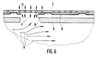
- Fig. 1 explains the Heigas overheating protection device according to the invention for the flame tube 1 of an annular combustion chamber of gas turbine engines, in which an outer and inner annular metal wall 2, 3 including cavities 4, 5 are shielded from the hot gas flow H by outer and inner wall elements 6, 7; the metal walls 2, 3 should be acted upon by means of cooling air removed from the compressor;
- the outer metal wall 2 illustrated here using the example of the outer metal wall 2, the same is to be lined with a thin sheet metal skin 8 within the cavity 4, which includes two spaces 9, 10 (FIGS. 2 to 4) with the outer metal wall, that communicate with cooling air openings 11 in the metal wall 2; the sheet metal skin should have a melting point which is the same as that of the metal wall 2 or which is below the melting point of the metal wall 2.
- the outer and inner wall elements 6, 7 should also be manufactured as shingle-like or scale-like hot gas shielding elements made of a high-temperature-resistant metallic or ceramic material.
- the z. B. consist of a nickel-based alloy.
- the metal walls 2, 3 are supporting outer or inner walls of the flame tube 1 and each have an outer, for. B. 12 (Fig. 3 and 4), or inner annular secondary air channel are acted upon by means of cooling air removed at the high pressure compressor end.
- the inner hot gas shielding can be broken down into a plurality of individual wall elements which are divided in the axial and / or circumferential direction and are arranged while leaving distances (for example axial distances 13, FIGS. 2, 3 and 4) between adjacent abutting edges.
- the individual inner wall elements 6, 7 can be straight or curved, following the flame tube contour in question.
- the wall elements 6, 7 can be inserted axially in circumferential grooves, the circumferential grooves being arranged on radially projecting webs, which in turn can be integral components of the relevant outer and inner, load-bearing metallic walls 2, 3 (FIG. 1) .
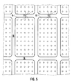
- each gap 9, 10 should have its own perforated sections 14, 15 provided with cooling air bores 11. 5, these perforation sections 14, 15 z. B. rectangular and uniformly spaced apart and arranged, the latter also applies to the interspaces 9, 10
- the previously mentioned thin sheet metal skin 8 should also be positively connected to the relevant metal wall 2 or 3 along the unperforated sections 16 (FIG. 5).
- the sheet metal skin 8 can be connected to the non-perforated sections 16 of the outer metal wall 2 here, for example, by means of local bends 17.
- the sheet metal skin 8 can be connected to the relevant metal wall along inwardly projecting web ends (webs 18).
- the sheet metal skin 8 can be connected to the relevant metal wall 2 with the interposition of spacer plates or strips 19.
- the strips 19 form the lateral boundary of the spaces 9, 10.
- the sheet metal skin 8 can be welded to the relevant metal wall 2 (FIG. 2) or soldered (FIG. 3) or riveted (FIG. 4).
- the defective wall element 6 and the defective part of the sheet metal skin 8 can be replaced. Contrary to the representation according to FIG. 1, a hot gas flow H which takes place from left to right is used as the basis for the exemplary embodiment according to FIG. 6.
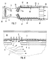
- FIG. 7 and 8 illustrate the application and design of the device according to the invention in an afterburner of a turbine jet engine.
- the latter can be designed, for example, as a multi-shaft, two-stream engine.
- the hot gas stream G leaving the low-pressure turbine 20 reaches, together with a blower air stream S fed from the secondary duct 21, with mutual intermixing, into the axially downstream afterburner jet pipe 22 After- or additional combustion takes place.
- an adjusting thrust nozzle 24 ' on the nozzle flaps 25 of which pivotable about transverse axes, an axially displaceable nozzle adjusting band 26 acts, which is actuated upstream by means of pneumatic adjusting cylinders 27 attached laterally on the outside.
- the effective thrust nozzle outlet cross section can be adapted to the hot gas mass flow rate which increases when the afterburning is switched on.
- the metal wall 2 forms a rotationally symmetrical inner peripheral wall of the jet pipe 22; between the metal wall 2 and the jet pipe wall is a rotationally symmetrical cooling air supply duct 28 formed, which is acted upon by relatively cool compressor or blower air, which flows out of the bypass or secondary air duct 21 along the outer edge zone into the cooling air supply duct 28.
- An inner heat shield 30 of the afterburner jet tube 22 here again consists of the inner wall elements 6 already mentioned.
- the effect of the design according to the invention in connection with FIG. 8 is therefore in principle identical to that which has already been explained in detail for FIG. 6 .
- the previously discussed inventive alternatives according to FIGS. 3, 4 and 5 can be used analogously for an afterburner jet pipe in the sense of FIG. 7.
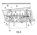
- FIG. 9 illustrates an alternative application of the invention as a high-pressure turbine blade casing, the metal wall 2 being acted upon by an air space L enclosed between the latter and an outer housing wall 31 by means of air L extracted from the compressor end, and a wall element 6 ′ divided into peripheral segments at the tips of the blades 33 of the high-pressure turbine turned in the turbine hot runner.
- the annular space 32 is connected via obliquely positioned air supply bores 34 to an outer housing annular space 35 which is acted upon by the cooling or thermal control air removed from the compressor end.
- a shingle-shaped, e.g. ceramic wall element 6 ' the effects described above for FIG. 6 result in an analogous manner.
- Cooling air is supplied at least partially in normal operation as sealing air Sp to the hot gas duct downstream of the blades 33.
- the metal wall 2 is a component of the supporting metallic core of the blade, the wall element 6 which is directly exposed to the hot gas flow H forming the outer blade shell;
- the cooling air F is e.g. guided from the blade root 36 into a core cavity 37 and from there through the holes 11 in the metal wall 2 to the spaces 10, 9, 38 which, as a result of the arrangement of the sheet metal skin 8 applied to the core-side metal wall 2 in at least one nose edge side here Cavity 4- are formed between the metal wall 2 of the core and the outer wall element 6-.
- the advantageous effect of the invention in the event of a break or damage to the outer wall element 6 here corresponds analogously to that as was previously discussed by way of example for an annular combustion chamber flame tube wall in the sense of FIG. 6.
- the basis is, moreover, that the cooling air, which normally flows exclusively into the spaces 10, 9, 38, flows around the core after cooling the high-temperature-stressed nose edge region, for example laterally on the outside in the downstream direction, and then in a suitable manner Channels on the blade trailing edge flow into the hot gas flow.
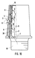
- the blade casing (outer wall element 6) can be made from several interchangeable parts; also in the case of FIG. 10, the high-temperature load can also be used Blade sheath (wall element 6) made of a suitable ceramic or metallic material.
Landscapes
- Engineering & Computer Science (AREA)
- Mechanical Engineering (AREA)
- General Engineering & Computer Science (AREA)
- Chemical & Material Sciences (AREA)
- Combustion & Propulsion (AREA)
- Materials Engineering (AREA)
- Ceramic Engineering (AREA)
- Turbine Rotor Nozzle Sealing (AREA)
Applications Claiming Priority (2)
| Application Number | Priority Date | Filing Date | Title |
|---|---|---|---|
| DE19863615226 DE3615226A1 (de) | 1986-05-06 | 1986-05-06 | Heissgasueberhitzungsschutzeinrichtung fuer gasturbinentriebwerke |
| DE3615226 | 1986-05-06 |
Publications (3)
| Publication Number | Publication Date |
|---|---|
| EP0244693A2 EP0244693A2 (de) | 1987-11-11 |
| EP0244693A3 EP0244693A3 (en) | 1990-05-02 |
| EP0244693B1 true EP0244693B1 (de) | 1992-07-29 |
Family
ID=6300236
Family Applications (1)
| Application Number | Title | Priority Date | Filing Date |
|---|---|---|---|
| EP87105860A Expired - Lifetime EP0244693B1 (de) | 1986-05-06 | 1987-04-22 | Heissgasüberhitzungsschutzeinrichtung für Gasturbinentriebwerke |
Country Status (4)
| Country | Link |
|---|---|
| US (1) | US5027604A (enExample) |
| EP (1) | EP0244693B1 (enExample) |
| JP (1) | JP2510573B2 (enExample) |
| DE (1) | DE3615226A1 (enExample) |
Families Citing this family (52)
| Publication number | Priority date | Publication date | Assignee | Title |
|---|---|---|---|---|
| ES2051519T3 (es) * | 1990-07-17 | 1994-06-16 | Siemens Ag | Trozo de tubo, especialmente tubo de combustion con bastidor de apoyo refrigerado para un revestimiento resistente al calor. |
| US5687572A (en) * | 1992-11-02 | 1997-11-18 | Alliedsignal Inc. | Thin wall combustor with backside impingement cooling |
| DE4328294A1 (de) * | 1993-08-23 | 1995-03-02 | Abb Management Ag | Verfahren zur Kühlung eines Bauteils sowie Vorrichtung zur Durchführung des Verfahrens |
| DE4335413A1 (de) * | 1993-10-18 | 1995-04-20 | Abb Management Ag | Verfahren und Vorrichtung zur Kühlung einer Gasturbinenbrennkammer |
| JP3110227B2 (ja) * | 1993-11-22 | 2000-11-20 | 株式会社東芝 | タービン冷却翼 |
| US6182451B1 (en) * | 1994-09-14 | 2001-02-06 | Alliedsignal Inc. | Gas turbine combustor waving ceramic combustor cans and an annular metallic combustor |
| US5749229A (en) * | 1995-10-13 | 1998-05-12 | General Electric Company | Thermal spreading combustor liner |
| US20020005152A1 (en) * | 1996-03-29 | 2002-01-17 | Mitsui Engineering And Shipbuilding Company Limited | High temperature air heater and waste treatment equipment |
| US5906093A (en) * | 1997-02-21 | 1999-05-25 | Siemens Westinghouse Power Corporation | Gas turbine combustor transition |
| US6019575A (en) * | 1997-09-12 | 2000-02-01 | United Technologies Corporation | Erosion energy dissipater |
| JP4315599B2 (ja) | 1998-08-31 | 2009-08-19 | シーメンス アクチエンゲゼルシヤフト | タービン翼 |
| ITMI991207A1 (it) * | 1999-05-31 | 2000-12-01 | Nuovo Pignone Spa | Camera di combustione per turbine a gas |
| RU2271454C2 (ru) * | 2000-12-28 | 2006-03-10 | Альстом Текнолоджи Лтд | Устройство площадок в прямоточной осевой газовой турбине с улучшенным охлаждением участков стенки и способ уменьшения потерь через зазоры |
| RU2211409C2 (ru) * | 2001-07-05 | 2003-08-27 | Открытое акционерное общество "Авиадвигатель" | Трубчато-кольцевая камера сгорания газотурбинного двигателя |
| US6495207B1 (en) * | 2001-12-21 | 2002-12-17 | Pratt & Whitney Canada Corp. | Method of manufacturing a composite wall |
| RU2215241C2 (ru) * | 2002-01-23 | 2003-10-27 | Открытое акционерное общество "Авиадвигатель" | Камера сгорания газотурбинного двигателя |
| KR20030076848A (ko) * | 2002-03-23 | 2003-09-29 | 조형희 | 핀-휜이 설치된 충돌제트/유출냉각기법을 이용한 가스터빈엔진의 연소실 냉각방법 |
| US6709230B2 (en) * | 2002-05-31 | 2004-03-23 | Siemens Westinghouse Power Corporation | Ceramic matrix composite gas turbine vane |
| US6648597B1 (en) | 2002-05-31 | 2003-11-18 | Siemens Westinghouse Power Corporation | Ceramic matrix composite turbine vane |
| US6758653B2 (en) | 2002-09-09 | 2004-07-06 | Siemens Westinghouse Power Corporation | Ceramic matrix composite component for a gas turbine engine |
| US7093359B2 (en) | 2002-09-17 | 2006-08-22 | Siemens Westinghouse Power Corporation | Composite structure formed by CMC-on-insulation process |
| US9068464B2 (en) * | 2002-09-17 | 2015-06-30 | Siemens Energy, Inc. | Method of joining ceramic parts and articles so formed |
| RU2243448C2 (ru) * | 2002-12-18 | 2004-12-27 | Федеральное государственное унитарное предприятие "Центральный институт авиационного моторостроения им. П.И. Баранова" | Камера сгорания |
| EP1431661A1 (de) * | 2002-12-19 | 2004-06-23 | Siemens Aktiengesellschaft | Ströhmungsführungskörper |
| US7311790B2 (en) * | 2003-04-25 | 2007-12-25 | Siemens Power Generation, Inc. | Hybrid structure using ceramic tiles and method of manufacture |
| US7363763B2 (en) * | 2003-10-23 | 2008-04-29 | United Technologies Corporation | Combustor |
| US7270175B2 (en) * | 2004-01-09 | 2007-09-18 | United Technologies Corporation | Extended impingement cooling device and method |
| US7351364B2 (en) * | 2004-01-29 | 2008-04-01 | Siemens Power Generation, Inc. | Method of manufacturing a hybrid structure |
| US7435058B2 (en) * | 2005-01-18 | 2008-10-14 | Siemens Power Generation, Inc. | Ceramic matrix composite vane with chordwise stiffener |
| GB2429515B (en) * | 2005-08-11 | 2008-06-25 | Rolls Royce Plc | Cooling method and apparatus |
| EP2216509A1 (de) * | 2009-02-04 | 2010-08-11 | Siemens Aktiengesellschaft | Turbinenbauteil mit leicht entfernbarer Schutzschicht, Satz von Turbinenbauteilen, eine Turbine und ein Verfahren zum Schützen eines Turbinenbauteils |
| US8721285B2 (en) * | 2009-03-04 | 2014-05-13 | Siemens Energy, Inc. | Turbine blade with incremental serpentine cooling channels beneath a thermal skin |
| US8745989B2 (en) * | 2009-04-09 | 2014-06-10 | Pratt & Whitney Canada Corp. | Reverse flow ceramic matrix composite combustor |
| US20100329887A1 (en) * | 2009-06-26 | 2010-12-30 | Andy Eifert | Coolable gas turbine engine component |
| US8256088B2 (en) * | 2009-08-24 | 2012-09-04 | Siemens Energy, Inc. | Joining mechanism with stem tension and interlocked compression ring |
| EP2354453B1 (en) * | 2010-02-02 | 2018-03-28 | Siemens Aktiengesellschaft | Turbine engine component for adaptive cooling |
| RU2483250C2 (ru) * | 2011-04-06 | 2013-05-27 | Открытое акционерное общество "Газпром" | Способ комбинированного охлаждения теплонапряженных элементов (варианты) |
| RU2469242C1 (ru) * | 2011-04-06 | 2012-12-10 | Открытое акционерное общество "Газпром" | Способ струйно-пористого охлаждения теплонапряженных элементов |
| US9115600B2 (en) | 2011-08-30 | 2015-08-25 | Siemens Energy, Inc. | Insulated wall section |
| EP2713009B1 (en) * | 2012-09-26 | 2015-03-11 | Alstom Technology Ltd | Cooling method and system for cooling blades of at least one blade row in a rotary flow machine |
| EP2965010B1 (en) * | 2013-03-05 | 2018-10-17 | Rolls-Royce Corporation | Dual-wall impingement, convection, effusion combustor tile |
| US10006367B2 (en) * | 2013-03-15 | 2018-06-26 | United Technologies Corporation | Self-opening cooling passages for a gas turbine engine |
| CN106661945A (zh) | 2014-09-04 | 2017-05-10 | 西门子公司 | 带有在燃气涡轮翼型的尾部冷却腔中形成近壁冷却通道的插入件的内部冷却系统 |
| JP6407413B2 (ja) | 2014-09-04 | 2018-10-17 | シーメンス アクチエンゲゼルシヤフトSiemens Aktiengesellschaft | ガスタービンエンジン用のタービン翼 |
| US10060270B2 (en) | 2015-03-17 | 2018-08-28 | Siemens Energy, Inc. | Internal cooling system with converging-diverging exit slots in trailing edge cooling channel for an airfoil in a turbine engine |
| DE102015215144B4 (de) | 2015-08-07 | 2017-11-09 | MTU Aero Engines AG | Vorrichtung und Verfahren zum Beeinflussen der Temperaturen in Innenringsegmenten einer Gasturbine |
| US9810434B2 (en) * | 2016-01-21 | 2017-11-07 | Siemens Energy, Inc. | Transition duct system with arcuate ceramic liner for delivering hot-temperature gases in a combustion turbine engine |
| US10760430B2 (en) * | 2017-05-31 | 2020-09-01 | General Electric Company | Adaptively opening backup cooling pathway |
| US10774656B2 (en) * | 2018-04-09 | 2020-09-15 | General Electric Company | Turbine airfoil multilayer exterior wall |
| US20200248568A1 (en) * | 2019-02-01 | 2020-08-06 | Rolls-Royce Plc | Turbine vane assembly with ceramic matrix composite components and temperature management features |
| FR3097271B1 (fr) * | 2019-06-12 | 2021-05-28 | Safran Aircraft Engines | Dispositif de refroidissement d’un carter d’une turbomachine |
| CN112412656A (zh) * | 2020-11-13 | 2021-02-26 | 中国航空工业集团公司沈阳飞机设计研究所 | 一种全复材蒙皮飞机发动机舱冷却结构 |
Family Cites Families (10)
| Publication number | Priority date | Publication date | Assignee | Title |
|---|---|---|---|---|
| NL113358C (enExample) * | 1957-02-18 | |||
| US4555901A (en) * | 1972-12-19 | 1985-12-03 | General Electric Company | Combustion chamber construction |
| GB1492049A (en) * | 1974-12-07 | 1977-11-16 | Rolls Royce | Combustion equipment for gas turbine engines |
| US4087199A (en) * | 1976-11-22 | 1978-05-02 | General Electric Company | Ceramic turbine shroud assembly |
| US4296606A (en) * | 1979-10-17 | 1981-10-27 | General Motors Corporation | Porous laminated material |
| US4302941A (en) * | 1980-04-02 | 1981-12-01 | United Technologies Corporation | Combuster liner construction for gas turbine engine |
| US4380896A (en) * | 1980-09-22 | 1983-04-26 | The United States Of America As Represented By The Secretary Of The Army | Annular combustor having ceramic liner |
| CA1183694A (en) * | 1981-06-12 | 1985-03-12 | Kenneth L. Rieke | Efficiently cooled combustor for a combustion turbine |
| US4432207A (en) * | 1981-08-06 | 1984-02-21 | General Electric Company | Modular catalytic combustion bed support system |
| DE3424345A1 (de) * | 1984-07-03 | 1986-01-09 | General Electric Co., Schenectady, N.Y. | Brennkammer |
-
1986
- 1986-05-06 DE DE19863615226 patent/DE3615226A1/de active Granted
-
1987
- 1987-04-22 EP EP87105860A patent/EP0244693B1/de not_active Expired - Lifetime
- 1987-05-01 JP JP62106492A patent/JP2510573B2/ja not_active Expired - Lifetime
-
1989
- 1989-01-03 US US07/293,574 patent/US5027604A/en not_active Expired - Fee Related
Also Published As
| Publication number | Publication date |
|---|---|
| EP0244693A3 (en) | 1990-05-02 |
| EP0244693A2 (de) | 1987-11-11 |
| US5027604A (en) | 1991-07-02 |
| JPS6325417A (ja) | 1988-02-02 |
| DE3615226A1 (de) | 1987-11-12 |
| DE3615226C2 (enExample) | 1990-03-01 |
| JP2510573B2 (ja) | 1996-06-26 |
Similar Documents
| Publication | Publication Date | Title |
|---|---|---|
| EP0244693B1 (de) | Heissgasüberhitzungsschutzeinrichtung für Gasturbinentriebwerke | |
| EP1005620B1 (de) | Hitzeschildkomponente mit kühlfluidrückführung | |
| EP1654495B1 (de) | Hitzeschildanordnung für eine ein heissgas führende komponente, insbesondere für eine brennkammer einer gasturbine | |
| EP1636526B1 (de) | Brennkammer | |
| EP2340397B1 (de) | Brennereinsatz für eine gasturbinenbrennkammer und gasturbine | |
| DE102005025823B4 (de) | Verfahren und Vorrichtung zum Kühlen einer Brennkammerauskleidung und eines Übergangsteils einer Gasturbine | |
| DE69320203T2 (de) | Struktur für eine gekühlte schaufel | |
| DE69526615T2 (de) | Wandaufbau für die Austrittsdüse eines Überschall-Strahltriebwerks | |
| DE60016058T2 (de) | Gekühlter Turbinen-Mantelring | |
| DE3019920C2 (de) | Einrichtung zur äußeren Ummantelung der Laufschaufeln von Axialturbinen für Gasturbinentriebwerke | |
| DE60209654T2 (de) | Verfahren zur Steuerung der Kühlungsströmung in eine Turbinenschaufel und Turbinenschaufel mit einer Strömungssteuerungsvorrichtung | |
| EP2809994B1 (de) | Hitzeschildelement für einen verdichterluftbypass um die brennkammer | |
| EP1409926B1 (de) | Prallkühlvorrichtung | |
| DE3942203A1 (de) | Turbinenanordnung mit heckseitig angebrachten ausstroemleitschaufeln | |
| EP2342427B1 (de) | Axial segmentierter leitschaufelträger für eine gasturbine | |
| DE3015653A1 (de) | Luftgekuehltes schaufelversteifungsband eines turbinenrotors mit halterungsmitteln | |
| EP2084368B1 (de) | Turbinenschaufel | |
| DE3428206C2 (de) | Statoranordnung in einer Gasturbine | |
| EP1836442A1 (de) | Hitzeschildelement | |
| EP1724526A1 (de) | Brennkammerschale, Gasturbinenanlage und Verfahren zum An- oder Abfahren einer Gasturbinenanlage | |
| EP2347100B1 (de) | Gasturbine mit kühleinsatz | |
| EP1588102B1 (de) | Hitzeschildelement, brennkammer sowie gasturbine | |
| EP1423647B1 (de) | Brennkammeranordnung | |
| EP1284391A1 (de) | Brennkammeranordnung für Gasturbinen | |
| EP1256695A1 (de) | Formstück zur Bildung eines Führungsrings für eine Gasturbine, sowie Gasturbine mit derartigem Führungsring |
Legal Events
| Date | Code | Title | Description |
|---|---|---|---|
| PUAI | Public reference made under article 153(3) epc to a published international application that has entered the european phase |
Free format text: ORIGINAL CODE: 0009012 |
|
| AK | Designated contracting states |
Kind code of ref document: A2 Designated state(s): BE CH FR GB IT LI |
|
| PUAL | Search report despatched |
Free format text: ORIGINAL CODE: 0009013 |
|
| AK | Designated contracting states |
Kind code of ref document: A3 Designated state(s): BE CH FR GB IT LI |
|
| 17P | Request for examination filed |
Effective date: 19900404 |
|
| 17Q | First examination report despatched |
Effective date: 19910315 |
|
| ITTA | It: last paid annual fee | ||
| GRAA | (expected) grant |
Free format text: ORIGINAL CODE: 0009210 |
|
| AK | Designated contracting states |
Kind code of ref document: B1 Designated state(s): BE CH FR GB IT LI |
|
| PG25 | Lapsed in a contracting state [announced via postgrant information from national office to epo] |
Ref country code: BE Effective date: 19920729 |
|
| ET | Fr: translation filed | ||
| GBT | Gb: translation of ep patent filed (gb section 77(6)(a)/1977) | ||
| ITF | It: translation for a ep patent filed | ||
| PLBE | No opposition filed within time limit |
Free format text: ORIGINAL CODE: 0009261 |
|
| STAA | Information on the status of an ep patent application or granted ep patent |
Free format text: STATUS: NO OPPOSITION FILED WITHIN TIME LIMIT |
|
| 26N | No opposition filed | ||
| PGFP | Annual fee paid to national office [announced via postgrant information from national office to epo] |
Ref country code: CH Payment date: 19950316 Year of fee payment: 9 |
|
| PGFP | Annual fee paid to national office [announced via postgrant information from national office to epo] |
Ref country code: GB Payment date: 19950320 Year of fee payment: 9 Ref country code: FR Payment date: 19950320 Year of fee payment: 9 |
|
| PG25 | Lapsed in a contracting state [announced via postgrant information from national office to epo] |
Ref country code: GB Effective date: 19960422 |
|
| PG25 | Lapsed in a contracting state [announced via postgrant information from national office to epo] |
Ref country code: LI Effective date: 19960430 Ref country code: CH Effective date: 19960430 |
|
| GBPC | Gb: european patent ceased through non-payment of renewal fee |
Effective date: 19960422 |
|
| REG | Reference to a national code |
Ref country code: CH Ref legal event code: PL |
|
| PG25 | Lapsed in a contracting state [announced via postgrant information from national office to epo] |
Ref country code: FR Effective date: 19961227 |
|
| REG | Reference to a national code |
Ref country code: FR Ref legal event code: ST |
|
| PG25 | Lapsed in a contracting state [announced via postgrant information from national office to epo] |
Ref country code: IT Free format text: LAPSE BECAUSE OF NON-PAYMENT OF DUE FEES;WARNING: LAPSES OF ITALIAN PATENTS WITH EFFECTIVE DATE BEFORE 2007 MAY HAVE OCCURRED AT ANY TIME BEFORE 2007. THE CORRECT EFFECTIVE DATE MAY BE DIFFERENT FROM THE ONE RECORDED. Effective date: 20050422 |