EP0244693B1 - Hot gas overheating protection device for gas turbine power plants - Google Patents
Hot gas overheating protection device for gas turbine power plants Download PDFInfo
- Publication number
- EP0244693B1 EP0244693B1 EP87105860A EP87105860A EP0244693B1 EP 0244693 B1 EP0244693 B1 EP 0244693B1 EP 87105860 A EP87105860 A EP 87105860A EP 87105860 A EP87105860 A EP 87105860A EP 0244693 B1 EP0244693 B1 EP 0244693B1
- Authority
- EP
- European Patent Office
- Prior art keywords
- wall
- metal
- sheet metal
- metal wall
- skin
- Prior art date
- Legal status (The legal status is an assumption and is not a legal conclusion. Google has not performed a legal analysis and makes no representation as to the accuracy of the status listed.)
- Expired - Lifetime
Links
- 238000013021 overheating Methods 0.000 title description 4
- 229910052751 metal Inorganic materials 0.000 claims description 84
- 239000002184 metal Substances 0.000 claims description 84
- 238000001816 cooling Methods 0.000 claims description 27
- 238000002485 combustion reaction Methods 0.000 claims description 22
- 238000002844 melting Methods 0.000 claims description 5
- 230000008018 melting Effects 0.000 claims description 5
- 230000002093 peripheral effect Effects 0.000 claims description 5
- 229910010293 ceramic material Inorganic materials 0.000 claims description 3
- 239000000463 material Substances 0.000 claims description 3
- 125000006850 spacer group Chemical group 0.000 claims description 2
- 239000011796 hollow space material Substances 0.000 claims 3
- 230000007246 mechanism Effects 0.000 claims 2
- 238000012216 screening Methods 0.000 claims 1
- 239000007789 gas Substances 0.000 description 21
- 230000000694 effects Effects 0.000 description 8
- 239000000919 ceramic Substances 0.000 description 6
- 239000000567 combustion gas Substances 0.000 description 5
- 230000002950 deficient Effects 0.000 description 4
- 239000000155 melt Substances 0.000 description 3
- 239000007769 metal material Substances 0.000 description 3
- PXHVJJICTQNCMI-UHFFFAOYSA-N Nickel Chemical compound [Ni] PXHVJJICTQNCMI-UHFFFAOYSA-N 0.000 description 2
- 238000012986 modification Methods 0.000 description 2
- 230000004048 modification Effects 0.000 description 2
- BASFCYQUMIYNBI-UHFFFAOYSA-N platinum Chemical compound [Pt] BASFCYQUMIYNBI-UHFFFAOYSA-N 0.000 description 2
- 229910052581 Si3N4 Inorganic materials 0.000 description 1
- 239000000956 alloy Substances 0.000 description 1
- 229910045601 alloy Inorganic materials 0.000 description 1
- 230000003197 catalytic effect Effects 0.000 description 1
- 238000006243 chemical reaction Methods 0.000 description 1
- 239000002737 fuel gas Substances 0.000 description 1
- 238000010438 heat treatment Methods 0.000 description 1
- 238000007689 inspection Methods 0.000 description 1
- 238000009413 insulation Methods 0.000 description 1
- 229910052759 nickel Inorganic materials 0.000 description 1
- 229910052697 platinum Inorganic materials 0.000 description 1
- 230000001681 protective effect Effects 0.000 description 1
- 238000007789 sealing Methods 0.000 description 1
- HBMJWWWQQXIZIP-UHFFFAOYSA-N silicon carbide Chemical compound [Si+]#[C-] HBMJWWWQQXIZIP-UHFFFAOYSA-N 0.000 description 1
- 229910010271 silicon carbide Inorganic materials 0.000 description 1
- HQVNEWCFYHHQES-UHFFFAOYSA-N silicon nitride Chemical compound N12[Si]34N5[Si]62N3[Si]51N64 HQVNEWCFYHHQES-UHFFFAOYSA-N 0.000 description 1
- 229910052709 silver Inorganic materials 0.000 description 1
- 239000004332 silver Substances 0.000 description 1
- 238000011144 upstream manufacturing Methods 0.000 description 1
Images


Classifications
-
- F—MECHANICAL ENGINEERING; LIGHTING; HEATING; WEAPONS; BLASTING
- F01—MACHINES OR ENGINES IN GENERAL; ENGINE PLANTS IN GENERAL; STEAM ENGINES
- F01D—NON-POSITIVE DISPLACEMENT MACHINES OR ENGINES, e.g. STEAM TURBINES
- F01D11/00—Preventing or minimising internal leakage of working-fluid, e.g. between stages
- F01D11/08—Preventing or minimising internal leakage of working-fluid, e.g. between stages for sealing space between rotor blade tips and stator
- F01D11/14—Adjusting or regulating tip-clearance, i.e. distance between rotor-blade tips and stator casing
- F01D11/20—Actively adjusting tip-clearance
- F01D11/24—Actively adjusting tip-clearance by selectively cooling-heating stator or rotor components
-
- F—MECHANICAL ENGINEERING; LIGHTING; HEATING; WEAPONS; BLASTING
- F01—MACHINES OR ENGINES IN GENERAL; ENGINE PLANTS IN GENERAL; STEAM ENGINES
- F01D—NON-POSITIVE DISPLACEMENT MACHINES OR ENGINES, e.g. STEAM TURBINES
- F01D21/00—Shutting-down of machines or engines, e.g. in emergency; Regulating, controlling, or safety means not otherwise provided for
- F01D21/04—Shutting-down of machines or engines, e.g. in emergency; Regulating, controlling, or safety means not otherwise provided for responsive to undesired position of rotor relative to stator or to breaking-off of a part of the rotor, e.g. indicating such position
- F01D21/045—Shutting-down of machines or engines, e.g. in emergency; Regulating, controlling, or safety means not otherwise provided for responsive to undesired position of rotor relative to stator or to breaking-off of a part of the rotor, e.g. indicating such position special arrangements in stators or in rotors dealing with breaking-off of part of rotor
-
- F—MECHANICAL ENGINEERING; LIGHTING; HEATING; WEAPONS; BLASTING
- F01—MACHINES OR ENGINES IN GENERAL; ENGINE PLANTS IN GENERAL; STEAM ENGINES
- F01D—NON-POSITIVE DISPLACEMENT MACHINES OR ENGINES, e.g. STEAM TURBINES
- F01D5/00—Blades; Blade-carrying members; Heating, heat-insulating, cooling or antivibration means on the blades or the members
- F01D5/12—Blades
- F01D5/14—Form or construction
- F01D5/18—Hollow blades, i.e. blades with cooling or heating channels or cavities; Heating, heat-insulating or cooling means on blades
- F01D5/187—Convection cooling
-
- F—MECHANICAL ENGINEERING; LIGHTING; HEATING; WEAPONS; BLASTING
- F01—MACHINES OR ENGINES IN GENERAL; ENGINE PLANTS IN GENERAL; STEAM ENGINES
- F01D—NON-POSITIVE DISPLACEMENT MACHINES OR ENGINES, e.g. STEAM TURBINES
- F01D5/00—Blades; Blade-carrying members; Heating, heat-insulating, cooling or antivibration means on the blades or the members
- F01D5/12—Blades
- F01D5/28—Selecting particular materials; Particular measures relating thereto; Measures against erosion or corrosion
-
- F—MECHANICAL ENGINEERING; LIGHTING; HEATING; WEAPONS; BLASTING
- F23—COMBUSTION APPARATUS; COMBUSTION PROCESSES
- F23R—GENERATING COMBUSTION PRODUCTS OF HIGH PRESSURE OR HIGH VELOCITY, e.g. GAS-TURBINE COMBUSTION CHAMBERS
- F23R3/00—Continuous combustion chambers using liquid or gaseous fuel
- F23R3/002—Wall structures
-
- F—MECHANICAL ENGINEERING; LIGHTING; HEATING; WEAPONS; BLASTING
- F23—COMBUSTION APPARATUS; COMBUSTION PROCESSES
- F23R—GENERATING COMBUSTION PRODUCTS OF HIGH PRESSURE OR HIGH VELOCITY, e.g. GAS-TURBINE COMBUSTION CHAMBERS
- F23R3/00—Continuous combustion chambers using liquid or gaseous fuel
- F23R3/007—Continuous combustion chambers using liquid or gaseous fuel constructed mainly of ceramic components
-
- F—MECHANICAL ENGINEERING; LIGHTING; HEATING; WEAPONS; BLASTING
- F05—INDEXING SCHEMES RELATING TO ENGINES OR PUMPS IN VARIOUS SUBCLASSES OF CLASSES F01-F04
- F05B—INDEXING SCHEME RELATING TO WIND, SPRING, WEIGHT, INERTIA OR LIKE MOTORS, TO MACHINES OR ENGINES FOR LIQUIDS COVERED BY SUBCLASSES F03B, F03D AND F03G
- F05B2260/00—Function
- F05B2260/30—Retaining components in desired mutual position
- F05B2260/301—Retaining bolts or nuts
- F05B2260/3011—Retaining bolts or nuts of the frangible or shear type
-
- F—MECHANICAL ENGINEERING; LIGHTING; HEATING; WEAPONS; BLASTING
- F05—INDEXING SCHEMES RELATING TO ENGINES OR PUMPS IN VARIOUS SUBCLASSES OF CLASSES F01-F04
- F05D—INDEXING SCHEME FOR ASPECTS RELATING TO NON-POSITIVE-DISPLACEMENT MACHINES OR ENGINES, GAS-TURBINES OR JET-PROPULSION PLANTS
- F05D2260/00—Function
- F05D2260/20—Heat transfer, e.g. cooling
- F05D2260/201—Heat transfer, e.g. cooling by impingement of a fluid
-
- F—MECHANICAL ENGINEERING; LIGHTING; HEATING; WEAPONS; BLASTING
- F23—COMBUSTION APPARATUS; COMBUSTION PROCESSES
- F23R—GENERATING COMBUSTION PRODUCTS OF HIGH PRESSURE OR HIGH VELOCITY, e.g. GAS-TURBINE COMBUSTION CHAMBERS
- F23R2900/00—Special features of, or arrangements for continuous combustion chambers; Combustion processes therefor
- F23R2900/03044—Impingement cooled combustion chamber walls or subassemblies
-
- Y—GENERAL TAGGING OF NEW TECHNOLOGICAL DEVELOPMENTS; GENERAL TAGGING OF CROSS-SECTIONAL TECHNOLOGIES SPANNING OVER SEVERAL SECTIONS OF THE IPC; TECHNICAL SUBJECTS COVERED BY FORMER USPC CROSS-REFERENCE ART COLLECTIONS [XRACs] AND DIGESTS
- Y02—TECHNOLOGIES OR APPLICATIONS FOR MITIGATION OR ADAPTATION AGAINST CLIMATE CHANGE
- Y02T—CLIMATE CHANGE MITIGATION TECHNOLOGIES RELATED TO TRANSPORTATION
- Y02T50/00—Aeronautics or air transport
- Y02T50/60—Efficient propulsion technologies, e.g. for aircraft
Definitions
- the invention relates to a device according to the preamble of claim 1.
- double-walled designs have been used e.g. selected according to DE-OS 34 24 345, which consists of a support structure (metallic outer jacket) and an inner cover structure (e.g. shingle-shaped, metallic or ceramic lining). If, due to damage, for example as a cause of local overheating or material reduction or the like, a metal shingle partially melts or a part of a ceramic shingle breaks off, the little-cooled metallic outer jacket of the combustion chamber is directly exposed to the attack of the hot combustion gases. There is a risk of the outer jacket burning through.
- a radiation-reflecting layer for example made of silver or platinum (vapor-deposited).
- a catalytic burner for gas turbine engines is known with a metal wall carrying a hot gas flow, which is acted upon by cooling air removed from the compressor and has cooling air openings which communicate with spaces which are formed between a sheet metal skin lining the metal wall, wherein the metal wall is shielded from the hot gas flow by at least one high-temperature-resistant wall element, which includes at least one cavity with the sheet metal skin.
- the invention has for its object to provide a device designed in the sense of the last-mentioned known case and on which the preamble of claim 1 is based which, despite a comparatively low cooling air requirement, allows optimal protection against overheating of the metal wall, in which the risk of the metal wall in question burning through - as the cause of damage to the wall element which normally shields the hot or combustion gases from the metal wall, should be minimized as far as possible.
- the invention can not only be used advantageously in combustion chambers of gas turbine engines; it can advantageously be used wherever metallic outer component structures, e.g. outer housing component structures, e.g. radially spaced neighborhood other linings are exposed to extremely high temperatures from the hot gases; so e.g. in turbine rotor blade casings which are cooled in a manner known per se by means of air drawn off from the compressor end (impact cooling systems), the casing section immediately adjacent to the rotor blade tips being thus exposed to the extremely high temperature influences.
- metallic outer component structures e.g. outer housing component structures, e.g. radially spaced neighborhood other linings
- other linings e.g. in turbine rotor blade casings which are cooled in a manner known per se by means of air drawn off from the compressor end (impact cooling systems), the casing section immediately adjacent to the rotor blade tips being thus exposed to the extremely high temperature influences.
- the invention is also suitable for use in afterburners of gas turbine engines in which extremely high combustion temperatures occur, so that a shingle-like or scale-like inner lining (heat shield) of the metallic outer jet pipe support structure can also be used there.
- the invention can also advantageously be used advantageously in cooled guide or rotor blades of gas turbine engines, i.e. in blade concepts in which cooling air is blown out of one or more inner blade cavities via one or more rows of impingement cooling bores in a metallic inner wall against wall sections of the outer blade shell which are at risk of temperature should be, with this extremely high temperature-stressed blade shell sections in particular the blade inlet and outlet edge sections.
- the subject matter of the invention is advantageous in terms of design and impact as follows.
- the outer supporting structure of the combustion chamber consists of a metallic outer jacket, which is provided with a large number of small radial bores, and one or more internal sheet metal parts with a thin wall.
- the thin sheet metal skin is positively connected locally to the support structure, but has a radial distance from the outer jacket in large areas.
- the thin sheet metal skin prevents air from entering through the many small radial bores in the combustion chamber.
- the melting point of the sheet metal material is chosen to be equal to or lower than that of the outer jacket. If a metal or ceramic shingle is damaged, the hot combustion gases first hit the thin-walled sheet metal skin. This area of the sheet metal skin is overheated and melts. This releases a number of radial bores in the outer jacket.
- the compressor air flows through these bores into the combustion chamber, thereby cooling the supporting structure very intensively in the area of the defective shingle and at the same time keeping the hot fuel gases away from the outer jacket. The next time the combustion chamber is inspected, the damaged shingle and / or part of the sheet metal skin will be replaced.
- Fig. 1 explains the Heigas overheating protection device according to the invention for the flame tube 1 of an annular combustion chamber of gas turbine engines, in which an outer and inner annular metal wall 2, 3 including cavities 4, 5 are shielded from the hot gas flow H by outer and inner wall elements 6, 7; the metal walls 2, 3 should be acted upon by means of cooling air removed from the compressor;
- the outer metal wall 2 illustrated here using the example of the outer metal wall 2, the same is to be lined with a thin sheet metal skin 8 within the cavity 4, which includes two spaces 9, 10 (FIGS. 2 to 4) with the outer metal wall, that communicate with cooling air openings 11 in the metal wall 2; the sheet metal skin should have a melting point which is the same as that of the metal wall 2 or which is below the melting point of the metal wall 2.
- the outer and inner wall elements 6, 7 should also be manufactured as shingle-like or scale-like hot gas shielding elements made of a high-temperature-resistant metallic or ceramic material.
- the z. B. consist of a nickel-based alloy.
- the metal walls 2, 3 are supporting outer or inner walls of the flame tube 1 and each have an outer, for. B. 12 (Fig. 3 and 4), or inner annular secondary air channel are acted upon by means of cooling air removed at the high pressure compressor end.
- the inner hot gas shielding can be broken down into a plurality of individual wall elements which are divided in the axial and / or circumferential direction and are arranged while leaving distances (for example axial distances 13, FIGS. 2, 3 and 4) between adjacent abutting edges.
- the individual inner wall elements 6, 7 can be straight or curved, following the flame tube contour in question.
- the wall elements 6, 7 can be inserted axially in circumferential grooves, the circumferential grooves being arranged on radially projecting webs, which in turn can be integral components of the relevant outer and inner, load-bearing metallic walls 2, 3 (FIG. 1) .
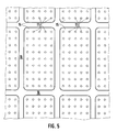
- each gap 9, 10 should have its own perforated sections 14, 15 provided with cooling air bores 11. 5, these perforation sections 14, 15 z. B. rectangular and uniformly spaced apart and arranged, the latter also applies to the interspaces 9, 10
- the previously mentioned thin sheet metal skin 8 should also be positively connected to the relevant metal wall 2 or 3 along the unperforated sections 16 (FIG. 5).
- the sheet metal skin 8 can be connected to the non-perforated sections 16 of the outer metal wall 2 here, for example, by means of local bends 17.
- the sheet metal skin 8 can be connected to the relevant metal wall along inwardly projecting web ends (webs 18).
- the sheet metal skin 8 can be connected to the relevant metal wall 2 with the interposition of spacer plates or strips 19.
- the strips 19 form the lateral boundary of the spaces 9, 10.
- the sheet metal skin 8 can be welded to the relevant metal wall 2 (FIG. 2) or soldered (FIG. 3) or riveted (FIG. 4).
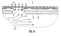
- the defective wall element 6 and the defective part of the sheet metal skin 8 can be replaced. Contrary to the representation according to FIG. 1, a hot gas flow H which takes place from left to right is used as the basis for the exemplary embodiment according to FIG. 6.
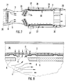
- FIG. 7 and 8 illustrate the application and design of the device according to the invention in an afterburner of a turbine jet engine.
- the latter can be designed, for example, as a multi-shaft, two-stream engine.
- the hot gas stream G leaving the low-pressure turbine 20 reaches, together with a blower air stream S fed from the secondary duct 21, with mutual intermixing, into the axially downstream afterburner jet pipe 22 After- or additional combustion takes place.
- an adjusting thrust nozzle 24 ' on the nozzle flaps 25 of which pivotable about transverse axes, an axially displaceable nozzle adjusting band 26 acts, which is actuated upstream by means of pneumatic adjusting cylinders 27 attached laterally on the outside.
- the effective thrust nozzle outlet cross section can be adapted to the hot gas mass flow rate which increases when the afterburning is switched on.
- the metal wall 2 forms a rotationally symmetrical inner peripheral wall of the jet pipe 22; between the metal wall 2 and the jet pipe wall is a rotationally symmetrical cooling air supply duct 28 formed, which is acted upon by relatively cool compressor or blower air, which flows out of the bypass or secondary air duct 21 along the outer edge zone into the cooling air supply duct 28.
- An inner heat shield 30 of the afterburner jet tube 22 here again consists of the inner wall elements 6 already mentioned.
- the effect of the design according to the invention in connection with FIG. 8 is therefore in principle identical to that which has already been explained in detail for FIG. 6 .
- the previously discussed inventive alternatives according to FIGS. 3, 4 and 5 can be used analogously for an afterburner jet pipe in the sense of FIG. 7.
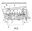
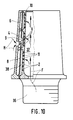
- FIG. 9 illustrates an alternative application of the invention as a high-pressure turbine blade casing, the metal wall 2 being acted upon by an air space L enclosed between the latter and an outer housing wall 31 by means of air L extracted from the compressor end, and a wall element 6 ′ divided into peripheral segments at the tips of the blades 33 of the high-pressure turbine turned in the turbine hot runner.
- the annular space 32 is connected via obliquely positioned air supply bores 34 to an outer housing annular space 35 which is acted upon by the cooling or thermal control air removed from the compressor end.
- a shingle-shaped, e.g. ceramic wall element 6 ' the effects described above for FIG. 6 result in an analogous manner.
- Cooling air is supplied at least partially in normal operation as sealing air Sp to the hot gas duct downstream of the blades 33.
- the metal wall 2 is a component of the supporting metallic core of the blade, the wall element 6 which is directly exposed to the hot gas flow H forming the outer blade shell;
- the cooling air F is e.g. guided from the blade root 36 into a core cavity 37 and from there through the holes 11 in the metal wall 2 to the spaces 10, 9, 38 which, as a result of the arrangement of the sheet metal skin 8 applied to the core-side metal wall 2 in at least one nose edge side here Cavity 4- are formed between the metal wall 2 of the core and the outer wall element 6-.
- the advantageous effect of the invention in the event of a break or damage to the outer wall element 6 here corresponds analogously to that as was previously discussed by way of example for an annular combustion chamber flame tube wall in the sense of FIG. 6.
- the basis is, moreover, that the cooling air, which normally flows exclusively into the spaces 10, 9, 38, flows around the core after cooling the high-temperature-stressed nose edge region, for example laterally on the outside in the downstream direction, and then in a suitable manner Channels on the blade trailing edge flow into the hot gas flow.
- the blade casing (outer wall element 6) can be made from several interchangeable parts; also in the case of FIG. 10, the high-temperature load can also be used Blade sheath (wall element 6) made of a suitable ceramic or metallic material.
Landscapes
- Engineering & Computer Science (AREA)
- Mechanical Engineering (AREA)
- General Engineering & Computer Science (AREA)
- Chemical & Material Sciences (AREA)
- Combustion & Propulsion (AREA)
- Ceramic Engineering (AREA)
- Materials Engineering (AREA)
- Turbine Rotor Nozzle Sealing (AREA)
Description
Die Erfindung bezieht sich auf eine Einrichtung nach dem Oberbegriff des Patentanspruchs 1.The invention relates to a device according to the preamble of claim 1.
Beispielsweise die Brennkammern moderner Gasturbinentreibwerke sind thermisch sehr hoch belastet, da für einen guten Wirkungsgrad des Triebwerks eine hohe Brennkammeraustritts- bzw. Turbineneintrittstemperatur erforderlich ist. Um u.a. den Kühlluftbedarf für die Brennkammerwand niedrig zu halten, wurden doppelwandige Bauweisen z.B. gemäß der DE-OS 34 24 345 gewählt, die aus einer Tragstruktur (metallischer Außenmantel) und einer innenliegenden Deckstruktur (z.B. schindelförmige, metallische oder keramische Auskleidung) besteht. Falls durch einen Schaden beispielsweise als Ursache örtlicher Überhitzung oder Werkstoffminderung oder dergleichen, eine Metallschindel teilweise schmilzt oder ein Teil einer Keramikschindel abbricht, ist der wenig gekühlte metallische Außenmantel der Brennkammer direkt dem Angriff der heißen Verbrennungsgase ausgesetzt. Es besteht die Gefahr des Durchbrennens des Außenmantels.For example, the combustion chambers of modern gas turbine engines are subjected to very high thermal loads, since a high combustion chamber outlet or turbine inlet temperature is required for good engine efficiency. To i.a. To keep the cooling air requirement for the combustion chamber wall low, double-walled designs have been used e.g. selected according to DE-OS 34 24 345, which consists of a support structure (metallic outer jacket) and an inner cover structure (e.g. shingle-shaped, metallic or ceramic lining). If, due to damage, for example as a cause of local overheating or material reduction or the like, a metal shingle partially melts or a part of a ceramic shingle breaks off, the little-cooled metallic outer jacket of the combustion chamber is directly exposed to the attack of the hot combustion gases. There is a risk of the outer jacket burning through.
Um die geschilderte Gefahr der unzulässig hohen Aufheizung bzw. die Durchbrenngefahr des Brennkammeraußenmantels zu verringern, wurde schon vorgeschlagen, die Innenseite dieses Bauteils mit einer strahlungsreflektierenden Schicht z.b. aus Silber oder Platin (aufgedampft), zu versehen.To the described risk of inadmissibly high heating or the risk of burning the outer shell of the combustion chamber reduce, it has already been proposed to provide the inside of this component with a radiation-reflecting layer, for example made of silver or platinum (vapor-deposited).
Ferner ist es schon bei stationären Gasturbientriebwerken vorgeschlagen worden, den Raum zwischen dem Außenmantel der Brennkammer und der inneren Auskleidung mit einer keramischen Isolierung sowie einer metallischen, federelastischen Beilage auszufüllen.Furthermore, it has already been proposed in stationary gas turbine engines to fill the space between the outer jacket of the combustion chamber and the inner lining with a ceramic insulation and a metallic, spring-elastic insert.
Auch im Wege dieser zuletzt genannten Maßnahmen und Brennkammerbauweise konnte den eingangs erwähnten Gefahren des Durchbrennens des metallischen Außenmantels - als Ursache einer Beschädigung oder eines Bruches der inneren Schindelstruktur der Brennkammer- nicht durchgreifend begegnet werden.Even by means of the last-mentioned measures and combustion chamber design, the dangers mentioned at the outset of the metal outer jacket burning through - as the cause of damage or breakage of the internal shingle structure of the combustion chamber - could not be countered comprehensively.
Aus der US-A- 4,432,207 ist ein Katalyt-Brenner für Gasturbinentriebwerke bekannt mit einer einen Heissgasstrom führenden Metallwand, die mit aus dem Verdichter entnommener Kühlluft beaufschlagt ist und Kühlluftöffnungen aufweist, die mit Zwischenräumen kommunizieren, welche zwischen einer die Metallwand auskleidenden Blechhaut ausgebildet sind, wobei die Metallwand durch mindestens ein hochtemperaturbeständiges Wandelement gegenüber der Heissgasströmung abgeschirmt ist, das mit der Blechhaut wenigstens einen Hohlraum einschließt.From US-A-4,432,207 a catalytic burner for gas turbine engines is known with a metal wall carrying a hot gas flow, which is acted upon by cooling air removed from the compressor and has cooling air openings which communicate with spaces which are formed between a sheet metal skin lining the metal wall, wherein the metal wall is shielded from the hot gas flow by at least one high-temperature-resistant wall element, which includes at least one cavity with the sheet metal skin.
Der Erfindung liegt die Aufgabe zugrunde, eine im Sinne des zuletzt genannten bekannten Falles ausgebildete und dem Oberbegriff des Patentanspruchs 1 zugrunde gelegte Einrichtung anzugeben, die trotz eines vergleichsweise geringen Kühlluftbedarfs einen optimalen Überhitzungsschutz der Metallwand erwarten läßt, worin die Gefahr des Durchbrennen der betreffenden Metallwand -als Ursache einer Beschädigung des die Heiß- bzw. Verbrennungsgase normalerweise gegenüber der Metallwand abschirmenden Wandelements- weitestgehend minimiert sein soll.The invention has for its object to provide a device designed in the sense of the last-mentioned known case and on which the preamble of claim 1 is based which, despite a comparatively low cooling air requirement, allows optimal protection against overheating of the metal wall, in which the risk of the metal wall in question burning through - as the cause of damage to the wall element which normally shields the hot or combustion gases from the metal wall, should be minimized as far as possible.
Die gestellte Aufgabe wird mit den Merkmalen des Kennzeichnungsteils des Patentanspruchs 1 erfindungsgemäß gelöst.The object is achieved with the features of the characterizing part of claim 1 according to the invention.
Die Erfindung kann nicht nur vorteilhaft bei Brennkammern von Gasturbinentriebwerken eingesetzt werden; sie kann vorteilhaft überall dort eingesetzt werden, wo metallischen äußeren Bauteilstrukturen, z.B. äußeren Gehäusebauteilstrukturen, in z.B. radial beabstandeter Nachbarschaft anderweitige Auskleidungen extrem hohen Temperaturen aus den Heißgasen ausgesetzt sind; so also z.B. bei Turbinenlaufschaufelummantelungen, die in für sich bekannter Weise mittels vom Verdichterende abgezapfter Luft gekühlt sind (Aufprallkühlsysteme), wobei der den Laufschaufelspitzen unmittelbar benachbarte Ummantelungsabschnitt also den extrem hohen Temperatureinflüssen ausgesetzt ist.The invention can not only be used advantageously in combustion chambers of gas turbine engines; it can advantageously be used wherever metallic outer component structures, e.g. outer housing component structures, e.g. radially spaced neighborhood other linings are exposed to extremely high temperatures from the hot gases; so e.g. in turbine rotor blade casings which are cooled in a manner known per se by means of air drawn off from the compressor end (impact cooling systems), the casing section immediately adjacent to the rotor blade tips being thus exposed to the extremely high temperature influences.
Die Erfindung eignet sich ferner für den Einsatz bei Nachbrennern von Gasturbinentriebwerken, in denen ganz extrem hohe Verbrennungstemperaturen auftreten, wobei also auch dort eine schindel- oder schuppenartige Innenauskleidung (Hitzeschild) der metallischen äußeren Strahlrohrtragstruktur zugrunde gelegt werden kann.The invention is also suitable for use in afterburners of gas turbine engines in which extremely high combustion temperatures occur, so that a shingle-like or scale-like inner lining (heat shield) of the metallic outer jet pipe support structure can also be used there.
Die Erfindung kann ferner vorteilhaft bei gekühlten Leit- oder Laufschaufeln von Gasturbinentriebwerken vorteilhaft eingesetzt werden, also bei Schaufelkonzepten, bei denen Kühlluft aus einem oder mehreren inneren Schaufelhohlräumen über eine oder mehrere Reihen von Prallkühlbohrungen in einer metallischen Innenwand gegen hoch-temperaturgefährdete Wandabschnitte des äußeren Schaufelmantels ausgeblasen werden soll, wobei es sich bei diesem extrem hoch-temperatur-belasteten Schaufelmantelpartien insbesondere um die Schaufelein- und Austrittskantenpartien handelt.The invention can also advantageously be used advantageously in cooled guide or rotor blades of gas turbine engines, i.e. in blade concepts in which cooling air is blown out of one or more inner blade cavities via one or more rows of impingement cooling bores in a metallic inner wall against wall sections of the outer blade shell which are at risk of temperature should be, with this extremely high temperature-stressed blade shell sections in particular the blade inlet and outlet edge sections.
Z.B. auf die Brennkammer eines Gasturbinentriebwerkes bezogen, stellt sich der Erfindungsgegenstand hinsichtlich Ausbildung und Auswirkung vorteilhaft wie folgt dar.For example, related to the combustion chamber of a gas turbine engine, the subject matter of the invention is advantageous in terms of design and impact as follows.
Die äußere Tragstruktur der Brennkammer besteht aus einem metallischen Außenmantel, der mit einer Vielzahl von kleinen Radialbohrungen versehen ist und aus einem oder mehreren innenliegenden Blechteilen mit dünner Wandstärke. Die dünne Blechhaut ist örtlich mit der Tragstruktur formschlüssig verbunden, hat aber in weiten Bereichen einen radialen Abstand zum Außenmantel.
Die dünne Blechhaut verhindert den Luftzutritt durch die vielen kleinen Radialbohrungen in die Brennkammer. Erfindungsgemäß ist dabei der Schmelzpunkt des Blechhautwerkstoffs gleich oder niedriger als der des Außenmantels gewählt. Bei einem Schaden einer Metall- oder Keramikschindel treffen die heißen Verbrennungsgase hier zunächst auf die dünnwandige Blechhaut auf. Dieser Bereich der Blechhaut wird überhitzt und schmilzt. Dadurch wird eine Anzahl von Radialbohrungen des Außenmantels freigegeben. Die Verdichterluft strömt durch diese Bohrungen in die Brennkammer, kühlt dadurch im Bereich der schadhaften Schindel die Tragstruktur sehr intensiv und hält gleichzeitig die heißen Brenngase von dem Außenmantel fern. Bei der nächsten Inspektion der Brennkammer werden die schadhafte Schindel und/oder ein Teil der Blechhaut ersetzt.The outer supporting structure of the combustion chamber consists of a metallic outer jacket, which is provided with a large number of small radial bores, and one or more internal sheet metal parts with a thin wall. The thin sheet metal skin is positively connected locally to the support structure, but has a radial distance from the outer jacket in large areas.
The thin sheet metal skin prevents air from entering through the many small radial bores in the combustion chamber. According to the invention, the melting point of the sheet metal material is chosen to be equal to or lower than that of the outer jacket. If a metal or ceramic shingle is damaged, the hot combustion gases first hit the thin-walled sheet metal skin. This area of the sheet metal skin is overheated and melts. This releases a number of radial bores in the outer jacket. The compressor air flows through these bores into the combustion chamber, thereby cooling the supporting structure very intensively in the area of the defective shingle and at the same time keeping the hot fuel gases away from the outer jacket. The next time the combustion chamber is inspected, the damaged shingle and / or part of the sheet metal skin will be replaced.
Vorteilhafte Ausgestaltungen der Erfindung ergeben sich aus den Patentansprüchen 2 bis 14.Advantageous refinements of the invention result from
Anhand der Zeichnungen ist die Erfindung beispielsweise weiter erläutert; es zeigen:
- Fig. 1
- die Erfindung anhand eines von der Seite sowie teilweise aufgebrochen dargestellten Ringbrennkammer-Flammrchrabschnitts,
- Fig. 2
- die aufgebrochene Einzelheit x der Fig. 1, jedoch in vergrößertem Maßstab wiedergegeben,
- Fig. 3
- eine erste Abwandlung der vergrößert wiedergegebenen Einzelheit aus Fig. 1,
- Fig. 4
- eine zweite Abwandlung der vergrößert wiedergegebenen Einzelheit aus Fig. 1,
- Fig. 5
- eine Abwicklung gemäß Schnitt A-A der Fig. 2,
- Fig. 6
- die Einzelheit nach Fig. 2 unter Verdeutlichung der Auswirkungen der Erfindung,
- Fig. 7
- erfindungsgemäße Einzelheiten an einem als Längsschnitt dargestellten Nachbrennerstrahlrohr eines Turbinenstrahltriebwerks,
- Fig. 8
- eine die Auswirkungen der Erfindung verdeutlichende Einzelheit im Sinne von Fig. 6, hier jedoch auf den Nachbrenner nach Fig. 7 bezogen,
- Fig. 9
- eine die Auswirkungen der Erfindung an einer abschnittsweise sowie als Längsschnitt dargestellten Turbinenlaufschaufelummantelung verdeutlichend und
- Fig. 1O
- eine teilweise in Seitenansicht sowei teilweise entlang der gesamten Schaufelmantelhöhe aufgebrochen dargestellte Turbinenlaufschaufel mit erfindungsgemäßen Einzelheiten, durch Radialschnitt verkörpert.
- Fig. 1
- the invention with reference to an annular combustion chamber flame section shown from the side and partially broken away,
- Fig. 2
- the broken detail x of FIG. 1, but shown on an enlarged scale,
- Fig. 3
- 2 shows a first modification of the enlarged detail from FIG. 1,
- Fig. 4
- 2 shows a second modification of the enlarged detail from FIG. 1,
- Fig. 5
- a development according to section AA of FIG. 2,
- Fig. 6
- the detail of FIG. 2 clarifying the effects of the invention,
- Fig. 7
- Details according to the invention on an afterburner jet pipe of a turbine jet engine, shown as a longitudinal section,
- Fig. 8
- 6 shows a detail clarifying the effects of the invention, but related here to the afterburner according to FIG. 7,
- Fig. 9
- a clarifying the effects of the invention on a turbine blade shroud and shown in sections and as a longitudinal section
- Fig. 10
- a turbine rotor blade shown partially broken away in a side view and partially broken open along the entire blade shell height with details according to the invention, embodied by radial section.
Fig. 1 erläutert die erfindungsgemäße Heigasüberhitzungsschutzeinrichtung für das Flammrohr 1 einer Ringbrennkammer von Gasturbinentriebwerken, bei der eine äußere und innere ringförmige Metallwand 2, 3 unter Einschluß von Hohlräumen 4, 5 durch äußere und innere Wandelemente 6, 7 gegenüber der Heißgasströmung H abgeschirmt sind; die Metallwände 2, 3 sollen mittels aus dem Verdichter entnommener Kühlluft beaufschlagt sein; gemäß Einzelheit x der Fig. 1 soll hier, am Beispiel der äußeren Metallwand 2 verdeutlicht, diesselbe innerhalb des Hohlraums 4 mit einer dünnen Blechhaut 8 ausgekleidet sein, welche mit der äußeren Metallwand 2 Zwischenräume 9, 10 (Fig. 2 bis 4) einschließt, die mit Kühlluftöffnungen 11 in der Metallwand 2 kommunizieren; dabei soll die Blechhaut einen Schmelzpunkt aufweisen, der demjenigen der Metallwand 2 gleich ist oder der unterhalb des Schmelzpunktes der Metallwand 2 liegt.Fig. 1 explains the Heigas overheating protection device according to the invention for the flame tube 1 of an annular combustion chamber of gas turbine engines, in which an outer and inner
Die äußeren und inneren Wandelemente 6, 7 sollen ferner als schindel- oder schuppenartige Heißgasabschirmelemente aus einem hoch-temperaturbeständigen metallischen oder keramischen Werkstoff gefertigt sein.The outer and
Als keramische Werkstoffe für die Wandelemente 6, 7 kommen z. B. heißgepreßtes oder selbstgesintertes Siliziumkarbid oder gegebenenfalls reaktionsgesintertes Siliziumnitird infrage.As ceramic materials for the
Als metallische Werkstoffe für die dünne Blechhaut 8 bzw. die metallische Ausführung der Wandelemente kommen z. B. zünder- und temperaturbeständige Werkstoffe infrage, die z. B. aus einer Nickelbasislegierung bestehen.As metallic materials for the thin
Zu Fig. 1 bis 4 wäre ferner zu vermerken, daß die Metallwände 2, 3 tragende Außen- oder Innenwände des Flammrohrs 1 sind und jeweils über einen zwischen Außengehäusestrukturbauteilen und dem Flammrohr 1 ausgebildeten äußeren, z. B. 12 (Fig. 3 und 4), oder inneren ringförmigen Sekundärluftkanal mittels am Hochdruckverdichterende entnommener Kühlluft beaufschlagt sind.1 to 4 it should also be noted that the
Erfindungsgemäß kann die innere Heißgasabschirmung in mehrere in Ax- und/oder Umfangsrichtung aufgeteilte Einzelwandelemente zergliedert sein, die unter Belassung von Abständen (z. B. Axialabstände 13, Fig. 2, 3 und 4) zwischen benachbarten Stoßkanten angeordnet sind.According to the invention, the inner hot gas shielding can be broken down into a plurality of individual wall elements which are divided in the axial and / or circumferential direction and are arranged while leaving distances (for example
Wie ferner aus Fig. 1 bis 4 hervorgeht, können die einzelnen inneren Wandelemente 6, 7 der betreffenden Flammrohrkontur folgend, gerade oder gewölbt ausgebildet sein. In nicht weiter dargestellter Weise können die Wandelemente 6, 7 in Umfangsnuten axial eingeschoben werden, wobei die Umfangsnuten an radial vorspringenden Stegen angeordnet sind, die wiederum integrale Bestandteile der betreffenden äußeren und inneren, tragenden metallischen Wände 2, 3 (Fig. 1) sein können.As can further be seen from FIGS. 1 to 4, the individual
Gemäß Fig. 2 bis 5 ist ferner erkennbar, daß jedem Zwischenraum 9, 10 eigene, mit Kühlluftbohrungen 11 versehene Belochungssektionen 14, 15 zugeordnet sein sollen. Nach Fig. 5 sind diese Belochungssektionen 14, 15 z. B. rechteckig sowie gleichförmig zueinander beabstandet ausgebildet und angeordnet, letzteres gilt auch für die beteffenden Zwischenräume 9, 10.According to FIGS. 2 to 5, it can also be seen that each
Die zuvor schon erwähnte dünne Blechhaut 8 soll ferner formschlüssig entlang der unbelochten Abschnitte 16 (Fig. 5) mit der betreffenden Metallwand 2 bzw. 3 verbunden sein.The previously mentioned thin
Wie in Fig. 2 dargestellt, kann die Blechhaut 8 über örtliche Ausbiegungen 17 mit den unbelochten Abschnitten 16 der hier beispielsweise äußeren Metallwand 2 verbunden sein.As shown in FIG. 2, the
Nach Fig. 3 kann die Blechhaut 8 entlang nach innen vorspringender Stegenden (Stege 18) mit der betreffenden Metallwand verbunden sein.3, the
Gemäß Fig. 4 kann die Blechhaut 8 unter Zwischenschaltung von Abstandsplatten oder-Streifen 19 mit der betreffenden Metallwand 2 verbunden sein. Die Streifen 19 bilden die seitliche Umgrenzung der Zwischenräume 9, 1O.4, the
Ferner kann die Blechhaut 8 mit der betreffenden Metallwand 2 verschweißt (Fig. 2) oder verlötet (Fig. 3) oder vernietet sein (Fig. 4).Furthermore, the
Fig. 6 erläutert dann am Ausführungsbeispiel nach Fig. 2 die Auswirkung der Erfindung im Falle eines Bruches (Abbrechstelle B) eines schindelförmigen Wandelements 6. In diesem Falle treffen die heißen Verbrennungsgase H zunächst auf die dünnwandige Blechhaut 8 auf. Dieser Bereich der Blechhaut 8 wird überhitzt und schmilzt. Dadurch wird eine Anzahl von Radialbohrungen 11 in der tragenden Metallwand 2 freigegeben. Gemäß Pfeilrichtung V strömt die Verdichterluft über diese Radialbohrungen 11 in den Verbrennungsraum des Flammrohrs 1, kühlt dadurch die Tragstruktur im Bereich des schadhaften Wandelements 6 sehr intensiv und hält gleichzeitig die heißen Verbrennungsgase H von der Metallwand 2 fern. Im Wege der nächsten Inspektion der Brennkammer kann das schadhafte Wandelement 6 sowie der schadhafte Teil der Blechhaut 8 ersetzt werden. Entgegen der Darstellung nach Fig. 1 ist beim Ausführungsbeispiel nach Fig. 6 eine von links nach rechts erfolgende Heißgasströmung H zugrundegelegt.6 then uses the exemplary embodiment according to FIG. 2 to explain the effect of the invention in the event of a fracture (break-off point B) of a shingle-shaped
Fig. 7 und 8 veranschaulichen die Anwendung und Ausbildung der erfindungsgemäßen Einrichtung bei einem Nachbrenner eines Turbinenstrahltriebwerks. Das letztere kann z.B. als Mehr-Wellen-Zweistromtriebwerk ausgebildet sein. Dabei gelangt der die Niederdruckturbine 2O verlassende Heißgasstrom G zusammen mit einem aus dem Sekundärkanal 21 zugeführten Gebläseluftstrom S unter gegenseitiger Durchmischung in das axial nachgeschaltete Nachbrennerstrahlrohr 22. Für die Nachverbrennung des Heißgas-Luftgemisches im Strahlrohr 22 sind Brennstoffeinspritzringe 23 sowie Flammenhalter 24 vorgesehen, strömab derselben die Nach- bzw. Zusatzverbrennung stattfindet.
Am stromabwärtigen Ende des Nachbrennerstrahlrohrs 22 ist eine Verstellschubdüse 24' angeordnet, an deren um Querachsen verschwenkbare Düsenklappen 25 ein axial verschiebbares Düsenverstellband 26 angreift, das stromaufwärtig über seitlich außen befestigte pneumatische Verstellzylinder 27 betätigt wird.
Mit der Verstelldüse 24' kann der wirksame Schubdüsenaustrittsquerschnitt an den bei Einschaltung der Nachverbrennung sich vergrößernden Heißgasmassendurchsatz angepaßt werden.7 and 8 illustrate the application and design of the device according to the invention in an afterburner of a turbine jet engine. The latter can be designed, for example, as a multi-shaft, two-stream engine. The hot gas stream G leaving the low-
At the downstream end of the
With the adjusting nozzle 24 ', the effective thrust nozzle outlet cross section can be adapted to the hot gas mass flow rate which increases when the afterburning is switched on.
Gemäß Fig. 7 und 8 bildet die Metallwand 2 nach der Erfindung eine rotationssymmetrische innere Umfangswand des Strahlrohrs 22 aus; zwischen Metallwand 2 und Strahlrohrwand ist ein rotationssymmetrischer Kühlluftzufuhrkanal 28 ausgebildet, der mit verhältnismäßig kühler Verdichter- oder Gebläseluft beaufschlagt ist, die aus dem Nebenstrom- oder Sekundärluftkanal 21 entlang der äußeren Randzone in den Kühlluftzufuhrkanal 28 abfließt. Ein innerer Hitzeschild 3O des Nachbrennerstrahlrohrs 22 besteht hier wiederum aus den zuvor schon erwähnten inneren Wandelementen 6. Die erfindungsgemäße Auswirkung der Ausbildung in Verbindung mit Fig. 8 ist also im Prinzip identisch mit derjenigen, wie sie bereits zu Fig. 6 schon ausführlich erläutert worden ist.
Im übrigen können für ein Nachbrennerstrahlrohr im Sinne der Fig. 7 auch die zuvor erörterten Erfindungsalternativen nach den Fig. 3, 4 und 5 sinngemäß zugrunde gelegt werden.7 and 8, the
For the rest, the previously discussed inventive alternatives according to FIGS. 3, 4 and 5 can be used analogously for an afterburner jet pipe in the sense of FIG. 7.
Fig. 9 veranschaulicht eine Anwendungsalternative der Erfindung als Hochdruckturbinenlaufschaufelummantelung, wobei die Metallwand 2 über einen zwischen dieser und einer Außengehäusewand 31 eingeschlossenen Ringraum 32 mittels vom Verdichterende entnommener Luft L beaufschlagt ist und wobei ein in Umfangssegmente aufgeteiltes Wandelement 6' den Spitzen der Laufschaufeln 33 der Hochdruckturbine im Turbinenheißkanal zugekehrt ist. Der Ringraum 32 ist über schräg angestellte Luftzufuhrbohrungen 34 mit einem äußerem Gehäuseringraum 35 in Verbindung, der mittels der vom Verdichterende entnommener Kühl- bzw. thermische Steuerluft beaufschlagt ist. Im Falle eines Bruches eines schindelförmigen, z.B. keramischen Wandelements 6' ergeben sich die zuvor zu Fig. 6 beschriebenen Auswirkungen in sinngemäßer Weise.FIG. 9 illustrates an alternative application of the invention as a high-pressure turbine blade casing, the
Gemäß Fig. 9 kann die aus dem Zwischenraum 9 bzw. Zwischenräumen -zwischen der Blechhaut 8 und der Metallwand 2-abfließende Kühlluft zumindest teilweise im Normalbetrieb als Sperrluft Sp dem Heißgaskanal -stromab der Laufschaufeln 33- zugeführt werden.According to FIG. 9, the one flowing out of the
Fig. 1O verkörpert die Erfindung bei einer mittels aus dem Verdichter entnommener Luft gekühlten Turbinenlaufschaufel eines Gasturbinentriebwerks; dabei ist die Metallwand 2 Bestandteil des tragenden metallischen Kerns der Schaufel, wobei das der Heißgasströmung H unmittelbar ausgesetzte Wandelement 6 den äußeren Schaufelmantel bildet; die Kühlluft F wird hier z.B. vom Schaufelfuß 36 aus in einen Kernhohlraum 37 geführt und von dort über die in der Metallwand 2 enthaltenen Bohrungen 11 den Zwischenräumen 1O, 9, 38 zugeführt, die als Folge der Anordnung der auf die kernseitige Metallwand 2 aufgebrachten Blechhaut 8 in mindestens einem hier überwiegend nasenkantenseitigen Hohlraum 4 -zwischen der Metallwand 2 des Kerns und dem äußeren Wandelement 6- ausgebildet sind.1O embodies the invention in a turbine blade of a gas turbine engine cooled by means of air extracted from the compressor; the
Die vorteilhafte Auswirkung der Erfindung im Falle eines Bruches oder einer Beschädigung des hier äußeren Wandelements 6 entspricht sinngemäß derjenigen, wie sie beispielhaft für eine Ringbrennkammer-Flammrohrwand im Sinne der Fig. 6 zuvor erörtert worden ist.
Für die Laufschaufel nach Fig. 1O ist im übrigen zugrundegelegt, daß die normalerweise ausschließlich in die Zwischenräume 1O, 9, 38 abfließende Kühlluft, nach Kühlung des hoch-temperaturbelasteten Nasenkantenbereichs, z.B. seitlich außen in stromabwärtiger Richtung den Kern umströmt und dann auf geeignete Weise über Kanäle schaufelhinterkantenseitig in den Heißgasstrom abfließt.The advantageous effect of the invention in the event of a break or damage to the
For the rotor blade according to FIG. 1O, the basis is, moreover, that the cooling air, which normally flows exclusively into the
Auch im Falle der Fig. 1O kann der Schaufelmantel (äußeres Wandelement 6) aus mehreren auswechselbaren Teilen gefertigt sein; auch im Falle der Fig. 1O kann ferner der hochtemperaturbelastete Schaufelmantel (Wandelement 6) aus einem geeigneten keramischen oder metallischen Werkstoff gefertigt sein.In the case of FIG. 10, too, the blade casing (outer wall element 6) can be made from several interchangeable parts; also in the case of FIG. 10, the high-temperature load can also be used Blade sheath (wall element 6) made of a suitable ceramic or metallic material.
Das Laufschaufelkonzept nach Fig. 10 wäre im übrigen auch dann erfindungsgemäß praktikabel, wenn im Normalbetriebszustand (keine Schaufelmantelbeschädigung) von einer in den genannten Zwischenräumen 10, 9, 38 stillstehenden Luftströmung angegangen wird, wobei also die Zwischenräume, z. B. 9, 10 - wie im Falle der Ausführungsbeispiele nach Fig. 1 bis 6 - mittels vom Verdichter entnommener Druckluft gefüllt sind und erst im Schadensfalle des Mantels 6 der abschirmende und schützende Luftüberströmeffekt (Strömung V) - wie erwähnt - durchgreift.10 would also be practicable according to the invention if, in the normal operating state (no damage to the blade casing), an air flow which is at a standstill in the
Der Erfindungsgegenstand kann auch bei Turbinenleitschaufeln in der erwähnten Weise sinngemäß eingesetzt werden.The subject matter of the invention can also be used analogously in the case of turbine guide vanes in the manner mentioned.
Sowohl im Falle einer Leitschaufel als auch im Falle einer Laufschafel nach Fig. 10 könnte im übrigen auch vom Vorhandensein mehrerer einzelner druck- und/oder saugseitig angeordneter Zwischenräume ausgegangen werden, ähnlich gleich örtlich verteilt, wie dies bei der Belochungssektionsverteilung nach Fig. 5 schon beschrieben und dargestellt ist.Both in the case of a guide vane and in the case of a moving board according to FIG. 10, it could also be assumed that there are several individual gaps arranged on the pressure and / or suction side, similarly distributed locally, as already described for the perforation section distribution according to FIG. 5 and is shown.
Claims (14)
- Device for preventing the burning-through of a metal wall (2) of a gas turbine engine, which wall (2) is provided to guide a hot gas stream, is acted upon by cooling air taken from the compressor, and comprises cooling air apertures (11) which communicate with intermediate spaces (9, 10) incorporated between the metal wall (2) and a sheet metal skin (8) lining the metal wall (2), the metal wall (2) being shielded with respect to the hot gas stream by at least one high-temperature resistant wall element (6) bounding at least one hollow space (4) with the sheet metal skin (8), characterised in that:- the sheet metal skin (8) prevents air entering the hollow space through the cooling air apertures (11);- the sheet metal skin (8) has a wall thickness and a material melting point such that, if there is a breakage of the wall element (6), the cooling air apertures (11) are exposed by local melting of the sheet metal skin (8) and thus form, for the metal wall (2), an air screen (V) flowing away against the hot gas stream (H).
- Device according to Claim 1, characterised in that at least one wall element (6) is produced as a shingle or flake-like hot gas screening component, from a high-temperature resistant metal or ceramic material.
- Device according to Claims 1 and 2, characterised in that a separate perforated section (14, 15), provided with cooling air bores (11), is associated with each intermediate space (9, 10).
- Device according to Claim 3, characterised in that the perforated sections (14, 15) are constructed and disposed so as to be square or rectangular and at equal distances from one another.
- Device according to one or more of Claims 1 to 4, characterised in that the sheet metal skin (8) is connected to the metal wall (2) in a positive-locking manner along the unperforated sections (16).
- Device according to one or more of Claims 1 to 5, characterised in that the sheet metal skin (8) is connected to the unperforated sections (16) of the metal wall (2) by means of projecting sections (17).
- Device according to one or more of Claims 1 to 6, characterised in that the sheet metal skin (8) is connected to the metal wall (2) along inwardly projecting ends of struts (18).
- Device according to one or more of Claims 1 to 5, characterised in that the sheet metal skin (8) is connected to the metal wall (2) with the interposition of spacer plates or strips (19).
- Device according to one or more of Claims 1 to 8, characterised in that the sheet metal skin (8) is welded, soldered or riveted to the metal wall (2).
- Device according to one or more of Claims 1 to 9, preferably for an annular combustion chamber of gas turbine drive mechanisms, characterised in that the metal wall (2, 3) is the supporting outer or inner wall of the flame tube (1), and is acted upon in each case via an outer or inner annular secondary air duct (12) formed between outer housing structural parts and the flame tube by cooling air removed from the high-pressure compressor end.
- Device according to Claim 10, characterised in that the high-temperature resistant lining is separated into a plurality of individual wall elements (6, 7) divided in the axial and/or peripheral direction and leaving spaces between adjacent border edges.
- Device according to one or more of Claims 1 to 9 or according to Claim 11 for a reheater of a gas turbine jet engine, characterised in that the metal wall (2) is an inner peripheral wall of a reheater jet pipe (22) at a radial distance, wall elements (6) being formed as a shingle or flake-like heat shield (30).
- Device according to one or more of Claims 1 to 9 or according to Claim 11, characterised in that it is preferably in the form of an external high-pressure turbine rotor blade casing, the metal wall (2) being acted upon via an annular space (32) enclosed between the metal wall and an outer housing wall (31) by air taken from the compressor end, and a wall element (6') divided into peripheral segments facing the rotor blade tips of the high-pressure turbine in the turbine hot gas duct.
- Device according to one or more of Claims 1 to 9 for a turbine guide or rotor blade of a gas turbine drive mechanism cooled by means of air taken from the compressor, characterised in that the metal wall (2) is part of the supporting metal core of the blade, the wall element (6) directly exposed to the hot gas stream (H) forming the outer blade casing, and the cooling air being delivered from the blade core interior (37) via perforated sections (bores 11) in the metal wall (2) to the intermediate spaces (10, 9, 38) which, as a result of the arrangement of the sheet metal skin (8) mounted on the metal wall (2) on the core side, are formed in at least one hollow space (4) - between the metal wall (2) of the core and the outer wall element (6).
Applications Claiming Priority (2)
| Application Number | Priority Date | Filing Date | Title |
|---|---|---|---|
| DE3615226 | 1986-05-06 | ||
| DE19863615226 DE3615226A1 (en) | 1986-05-06 | 1986-05-06 | HOT GAS OVERHEATING PROTECTION DEVICE FOR GAS TURBINE ENGINES |
Publications (3)
| Publication Number | Publication Date |
|---|---|
| EP0244693A2 EP0244693A2 (en) | 1987-11-11 |
| EP0244693A3 EP0244693A3 (en) | 1990-05-02 |
| EP0244693B1 true EP0244693B1 (en) | 1992-07-29 |
Family
ID=6300236
Family Applications (1)
| Application Number | Title | Priority Date | Filing Date |
|---|---|---|---|
| EP87105860A Expired - Lifetime EP0244693B1 (en) | 1986-05-06 | 1987-04-22 | Hot gas overheating protection device for gas turbine power plants |
Country Status (4)
| Country | Link |
|---|---|
| US (1) | US5027604A (en) |
| EP (1) | EP0244693B1 (en) |
| JP (1) | JP2510573B2 (en) |
| DE (1) | DE3615226A1 (en) |
Families Citing this family (45)
| Publication number | Priority date | Publication date | Assignee | Title |
|---|---|---|---|---|
| EP0539359B1 (en) * | 1990-07-17 | 1994-04-20 | Siemens Aktiengesellschaft | Flame tube with a cooled supporting frame for a heat-resistant lining |
| US5687572A (en) * | 1992-11-02 | 1997-11-18 | Alliedsignal Inc. | Thin wall combustor with backside impingement cooling |
| DE4328294A1 (en) * | 1993-08-23 | 1995-03-02 | Abb Management Ag | Method for cooling a component and device for carrying out the method |
| DE4335413A1 (en) * | 1993-10-18 | 1995-04-20 | Abb Management Ag | Method and device for cooling a gas turbine combustion chamber |
| JP3110227B2 (en) * | 1993-11-22 | 2000-11-20 | 株式会社東芝 | Turbine cooling blade |
| US6182451B1 (en) * | 1994-09-14 | 2001-02-06 | Alliedsignal Inc. | Gas turbine combustor waving ceramic combustor cans and an annular metallic combustor |
| US5749229A (en) * | 1995-10-13 | 1998-05-12 | General Electric Company | Thermal spreading combustor liner |
| CN1215468A (en) * | 1996-03-29 | 1999-04-28 | 三井造船株式会社 | High temp. air heater and waste treatment equipment |
| US5906093A (en) * | 1997-02-21 | 1999-05-25 | Siemens Westinghouse Power Corporation | Gas turbine combustor transition |
| US6019575A (en) * | 1997-09-12 | 2000-02-01 | United Technologies Corporation | Erosion energy dissipater |
| DE59905944D1 (en) | 1998-08-31 | 2003-07-17 | Siemens Ag | TURBINE BLADE |
| KR20030076848A (en) * | 2002-03-23 | 2003-09-29 | 조형희 | Combustor liner of a gas turbine engine using impingement/effusion cooling method with pin-fin |
| US6709230B2 (en) * | 2002-05-31 | 2004-03-23 | Siemens Westinghouse Power Corporation | Ceramic matrix composite gas turbine vane |
| US6648597B1 (en) | 2002-05-31 | 2003-11-18 | Siemens Westinghouse Power Corporation | Ceramic matrix composite turbine vane |
| US6758653B2 (en) | 2002-09-09 | 2004-07-06 | Siemens Westinghouse Power Corporation | Ceramic matrix composite component for a gas turbine engine |
| US9068464B2 (en) * | 2002-09-17 | 2015-06-30 | Siemens Energy, Inc. | Method of joining ceramic parts and articles so formed |
| US7093359B2 (en) | 2002-09-17 | 2006-08-22 | Siemens Westinghouse Power Corporation | Composite structure formed by CMC-on-insulation process |
| EP1431661A1 (en) * | 2002-12-19 | 2004-06-23 | Siemens Aktiengesellschaft | Flow guiding body |
| US7311790B2 (en) * | 2003-04-25 | 2007-12-25 | Siemens Power Generation, Inc. | Hybrid structure using ceramic tiles and method of manufacture |
| US7363763B2 (en) * | 2003-10-23 | 2008-04-29 | United Technologies Corporation | Combustor |
| US7351364B2 (en) * | 2004-01-29 | 2008-04-01 | Siemens Power Generation, Inc. | Method of manufacturing a hybrid structure |
| US7435058B2 (en) * | 2005-01-18 | 2008-10-14 | Siemens Power Generation, Inc. | Ceramic matrix composite vane with chordwise stiffener |
| GB2429515B (en) * | 2005-08-11 | 2008-06-25 | Rolls Royce Plc | Cooling method and apparatus |
| EP2216509A1 (en) * | 2009-02-04 | 2010-08-11 | Siemens Aktiengesellschaft | Turbine component with easily removable protective layer, turbine component set, a turbine and method for protecting a turbine component |
| US8721285B2 (en) * | 2009-03-04 | 2014-05-13 | Siemens Energy, Inc. | Turbine blade with incremental serpentine cooling channels beneath a thermal skin |
| US8745989B2 (en) * | 2009-04-09 | 2014-06-10 | Pratt & Whitney Canada Corp. | Reverse flow ceramic matrix composite combustor |
| US20100329887A1 (en) * | 2009-06-26 | 2010-12-30 | Andy Eifert | Coolable gas turbine engine component |
| US8256088B2 (en) * | 2009-08-24 | 2012-09-04 | Siemens Energy, Inc. | Joining mechanism with stem tension and interlocked compression ring |
| EP2354453B1 (en) * | 2010-02-02 | 2018-03-28 | Siemens Aktiengesellschaft | Turbine engine component for adaptive cooling |
| RU2469242C1 (en) * | 2011-04-06 | 2012-12-10 | Открытое акционерное общество "Газпром" | Method of jet-porous cooling of heat-stressed elements |
| RU2483250C2 (en) * | 2011-04-06 | 2013-05-27 | Открытое акционерное общество "Газпром" | Combined cooling method of heat-stressed components (versions) |
| US9115600B2 (en) | 2011-08-30 | 2015-08-25 | Siemens Energy, Inc. | Insulated wall section |
| EP2713009B1 (en) * | 2012-09-26 | 2015-03-11 | Alstom Technology Ltd | Cooling method and system for cooling blades of at least one blade row in a rotary flow machine |
| CA2904200A1 (en) * | 2013-03-05 | 2014-09-12 | Rolls-Royce Corporation | Dual-wall impingement, convection, effusion combustor tile |
| US10006367B2 (en) * | 2013-03-15 | 2018-06-26 | United Technologies Corporation | Self-opening cooling passages for a gas turbine engine |
| CN106661945A (en) | 2014-09-04 | 2017-05-10 | 西门子公司 | Internal Cooling System With Insert Forming Nearwall Cooling Channels In An Aft Cooling Cavity Of A Gas Turbine Airfoil |
| EP3189214A1 (en) | 2014-09-04 | 2017-07-12 | Siemens Aktiengesellschaft | Internal cooling system with insert forming nearwall cooling channels in midchord cooling cavities of a gas turbine airfoil |
| WO2016148693A1 (en) | 2015-03-17 | 2016-09-22 | Siemens Energy, Inc. | Internal cooling system with converging-diverging exit slots in trailing edge cooling channel for an airfoil in a turbine engine |
| DE102015215144B4 (en) | 2015-08-07 | 2017-11-09 | MTU Aero Engines AG | Device and method for influencing the temperatures in inner ring segments of a gas turbine |
| US9810434B2 (en) * | 2016-01-21 | 2017-11-07 | Siemens Energy, Inc. | Transition duct system with arcuate ceramic liner for delivering hot-temperature gases in a combustion turbine engine |
| US10760430B2 (en) * | 2017-05-31 | 2020-09-01 | General Electric Company | Adaptively opening backup cooling pathway |
| US10774656B2 (en) * | 2018-04-09 | 2020-09-15 | General Electric Company | Turbine airfoil multilayer exterior wall |
| US20200248568A1 (en) * | 2019-02-01 | 2020-08-06 | Rolls-Royce Plc | Turbine vane assembly with ceramic matrix composite components and temperature management features |
| FR3097271B1 (en) * | 2019-06-12 | 2021-05-28 | Safran Aircraft Engines | Device for cooling a casing of a turbomachine |
| CN112412656A (en) * | 2020-11-13 | 2021-02-26 | 中国航空工业集团公司沈阳飞机设计研究所 | Full-composite-material skin aircraft engine cabin cooling structure |
Family Cites Families (10)
| Publication number | Priority date | Publication date | Assignee | Title |
|---|---|---|---|---|
| NL248467A (en) * | 1957-02-18 | |||
| US4555901A (en) * | 1972-12-19 | 1985-12-03 | General Electric Company | Combustion chamber construction |
| GB1492049A (en) * | 1974-12-07 | 1977-11-16 | Rolls Royce | Combustion equipment for gas turbine engines |
| US4087199A (en) * | 1976-11-22 | 1978-05-02 | General Electric Company | Ceramic turbine shroud assembly |
| US4296606A (en) * | 1979-10-17 | 1981-10-27 | General Motors Corporation | Porous laminated material |
| US4302941A (en) * | 1980-04-02 | 1981-12-01 | United Technologies Corporation | Combuster liner construction for gas turbine engine |
| US4380896A (en) * | 1980-09-22 | 1983-04-26 | The United States Of America As Represented By The Secretary Of The Army | Annular combustor having ceramic liner |
| CA1183694A (en) * | 1981-06-12 | 1985-03-12 | Kenneth L. Rieke | Efficiently cooled combustor for a combustion turbine |
| US4432207A (en) * | 1981-08-06 | 1984-02-21 | General Electric Company | Modular catalytic combustion bed support system |
| DE3424345A1 (en) * | 1984-07-03 | 1986-01-09 | General Electric Co., Schenectady, N.Y. | Combustion chamber |
-
1986
- 1986-05-06 DE DE19863615226 patent/DE3615226A1/en active Granted
-
1987
- 1987-04-22 EP EP87105860A patent/EP0244693B1/en not_active Expired - Lifetime
- 1987-05-01 JP JP62106492A patent/JP2510573B2/en not_active Expired - Lifetime
-
1989
- 1989-01-03 US US07/293,574 patent/US5027604A/en not_active Expired - Fee Related
Also Published As
| Publication number | Publication date |
|---|---|
| EP0244693A3 (en) | 1990-05-02 |
| JP2510573B2 (en) | 1996-06-26 |
| JPS6325417A (en) | 1988-02-02 |
| EP0244693A2 (en) | 1987-11-11 |
| DE3615226A1 (en) | 1987-11-12 |
| DE3615226C2 (en) | 1990-03-01 |
| US5027604A (en) | 1991-07-02 |
Similar Documents
| Publication | Publication Date | Title |
|---|---|---|
| EP0244693B1 (en) | Hot gas overheating protection device for gas turbine power plants | |
| EP1005620B1 (en) | Thermal shield component with recirculation of cooling fluid | |
| EP1654495B1 (en) | Heat shield arrangement for a high temperature gas conveying component, in particular for a gas turbine combustion chamber | |
| DE102005025823B4 (en) | Method and device for cooling a combustion chamber lining and a transition part of a gas turbine | |
| DE69320203T2 (en) | STRUCTURE FOR A COOLED SHOVEL | |
| DE69526615T2 (en) | Wall structure for the outlet nozzle of a supersonic jet engine | |
| DE60016058T2 (en) | Cooled turbine shroud | |
| DE3019920C2 (en) | Device for the outer casing of the rotor blades of axial turbines for gas turbine engines | |
| DE60209654T2 (en) | A method of controlling the flow of cooling into a turbine blade and turbine blade with a flow control device | |
| EP2809994B1 (en) | Heat-shield element for a compressor-air bypass around the combustion chamber | |
| EP1409926B1 (en) | Baffle cooling device | |
| DE3942203A1 (en) | TURBINE ARRANGEMENT WITH REAR FITTING VANE BLADES | |
| EP1636526A1 (en) | Combustion chamber | |
| EP2342427B1 (en) | Axial segmented vane support for a gas turbine | |
| DE3015653A1 (en) | AIR-COOLED BLADE REINFORCING TAPE OF A TURBINE ROTOR WITH BRACKETS | |
| EP2340397A1 (en) | Burner inserts for a gas turbine combustion chamber and gas turbine | |
| EP2084368B1 (en) | Turbine blade | |
| EP1836442A1 (en) | Heat shield element | |
| DE3428206C2 (en) | Stator arrangement in a gas turbine | |
| EP2347100B1 (en) | Gas turbine having cooling insert | |
| EP1284391A1 (en) | Combustion chamber for gas turbines | |
| EP1588102B1 (en) | Heat shield element, combustion chamber and gas turbine | |
| EP1423647B1 (en) | Combustion chamber arrangement | |
| EP1256695A1 (en) | Element for a gas turbine guiding ring and gas turbine comprising such element | |
| EP2184449A1 (en) | Guide vane support, gas turbine and gas or steam turbine engine with such a guide vane support |
Legal Events
| Date | Code | Title | Description |
|---|---|---|---|
| PUAI | Public reference made under article 153(3) epc to a published international application that has entered the european phase |
Free format text: ORIGINAL CODE: 0009012 |
|
| AK | Designated contracting states |
Kind code of ref document: A2 Designated state(s): BE CH FR GB IT LI |
|
| PUAL | Search report despatched |
Free format text: ORIGINAL CODE: 0009013 |
|
| AK | Designated contracting states |
Kind code of ref document: A3 Designated state(s): BE CH FR GB IT LI |
|
| 17P | Request for examination filed |
Effective date: 19900404 |
|
| 17Q | First examination report despatched |
Effective date: 19910315 |
|
| ITTA | It: last paid annual fee | ||
| GRAA | (expected) grant |
Free format text: ORIGINAL CODE: 0009210 |
|
| AK | Designated contracting states |
Kind code of ref document: B1 Designated state(s): BE CH FR GB IT LI |
|
| PG25 | Lapsed in a contracting state [announced via postgrant information from national office to epo] |
Ref country code: BE Effective date: 19920729 |
|
| ET | Fr: translation filed | ||
| GBT | Gb: translation of ep patent filed (gb section 77(6)(a)/1977) | ||
| ITF | It: translation for a ep patent filed | ||
| PLBE | No opposition filed within time limit |
Free format text: ORIGINAL CODE: 0009261 |
|
| STAA | Information on the status of an ep patent application or granted ep patent |
Free format text: STATUS: NO OPPOSITION FILED WITHIN TIME LIMIT |
|
| 26N | No opposition filed | ||
| PGFP | Annual fee paid to national office [announced via postgrant information from national office to epo] |
Ref country code: CH Payment date: 19950316 Year of fee payment: 9 |
|
| PGFP | Annual fee paid to national office [announced via postgrant information from national office to epo] |
Ref country code: GB Payment date: 19950320 Year of fee payment: 9 Ref country code: FR Payment date: 19950320 Year of fee payment: 9 |
|
| PG25 | Lapsed in a contracting state [announced via postgrant information from national office to epo] |
Ref country code: GB Effective date: 19960422 |
|
| PG25 | Lapsed in a contracting state [announced via postgrant information from national office to epo] |
Ref country code: LI Effective date: 19960430 Ref country code: CH Effective date: 19960430 |
|
| GBPC | Gb: european patent ceased through non-payment of renewal fee |
Effective date: 19960422 |
|
| REG | Reference to a national code |
Ref country code: CH Ref legal event code: PL |
|
| PG25 | Lapsed in a contracting state [announced via postgrant information from national office to epo] |
Ref country code: FR Effective date: 19961227 |
|
| REG | Reference to a national code |
Ref country code: FR Ref legal event code: ST |
|
| PG25 | Lapsed in a contracting state [announced via postgrant information from national office to epo] |
Ref country code: IT Free format text: LAPSE BECAUSE OF NON-PAYMENT OF DUE FEES;WARNING: LAPSES OF ITALIAN PATENTS WITH EFFECTIVE DATE BEFORE 2007 MAY HAVE OCCURRED AT ANY TIME BEFORE 2007. THE CORRECT EFFECTIVE DATE MAY BE DIFFERENT FROM THE ONE RECORDED. Effective date: 20050422 |