EP0244011A2 - Appareil de radiologie pourvu d'une partie motorisée - Google Patents
Appareil de radiologie pourvu d'une partie motorisée Download PDFInfo
- Publication number
- EP0244011A2 EP0244011A2 EP87200718A EP87200718A EP0244011A2 EP 0244011 A2 EP0244011 A2 EP 0244011A2 EP 87200718 A EP87200718 A EP 87200718A EP 87200718 A EP87200718 A EP 87200718A EP 0244011 A2 EP0244011 A2 EP 0244011A2
- Authority
- EP
- European Patent Office
- Prior art keywords
- drive
- shaft
- bearing
- ray
- motor
- Prior art date
- Legal status (The legal status is an assumption and is not a legal conclusion. Google has not performed a legal analysis and makes no representation as to the accuracy of the status listed.)
- Ceased
Links
Images


Classifications
-
- A—HUMAN NECESSITIES
- A61—MEDICAL OR VETERINARY SCIENCE; HYGIENE
- A61B—DIAGNOSIS; SURGERY; IDENTIFICATION
- A61B6/00—Apparatus for radiation diagnosis, e.g. combined with radiation therapy equipment
- A61B6/44—Constructional features of apparatus for radiation diagnosis
- A61B6/4476—Constructional features of apparatus for radiation diagnosis related to motor-assisted motion of the source unit
-
- A—HUMAN NECESSITIES
- A61—MEDICAL OR VETERINARY SCIENCE; HYGIENE
- A61B—DIAGNOSIS; SURGERY; IDENTIFICATION
- A61B6/00—Apparatus for radiation diagnosis, e.g. combined with radiation therapy equipment
- A61B6/44—Constructional features of apparatus for radiation diagnosis
- A61B6/4429—Constructional features of apparatus for radiation diagnosis related to the mounting of source units and detector units
- A61B6/4464—Constructional features of apparatus for radiation diagnosis related to the mounting of source units and detector units the source unit or the detector unit being mounted to ceiling
-
- A—HUMAN NECESSITIES
- A61—MEDICAL OR VETERINARY SCIENCE; HYGIENE
- A61B—DIAGNOSIS; SURGERY; IDENTIFICATION
- A61B6/00—Apparatus for radiation diagnosis, e.g. combined with radiation therapy equipment
- A61B6/44—Constructional features of apparatus for radiation diagnosis
- A61B6/4476—Constructional features of apparatus for radiation diagnosis related to motor-assisted motion of the source unit
- A61B6/4482—Constructional features of apparatus for radiation diagnosis related to motor-assisted motion of the source unit involving power assist circuits
-
- G—PHYSICS
- G05—CONTROLLING; REGULATING
- G05D—SYSTEMS FOR CONTROLLING OR REGULATING NON-ELECTRIC VARIABLES
- G05D3/00—Control of position or direction
- G05D3/12—Control of position or direction using feedback
- G05D3/14—Control of position or direction using feedback using an analogue comparing device
- G05D3/1472—Control of position or direction using feedback using an analogue comparing device with potentiometer
Definitions
- the invention relates to an X-ray device with the drive of a device part with a measuring device which measures the forces exerted on the device part and controls the drive accordingly.
- X-ray devices are known (DE-OS 2l 04 509 and DE-OS 23 6l 985).
- a measuring device In order to prevent the patient from being pinched by the device part moving with the force of the drive motor or from moving the device part against the floor or ceiling of the examination room, a measuring device must be provided which measures the force exerted on the device part and switches off the drive when the forces exerted on the device part change to a predetermined extent.
- the motor drive is connected to the device part via a rope and the measuring device detects the forces acting on the rope. This requires that when the rope is replaced, the measuring device - generally a strain gauge - must also be replaced, since it must be adapted to the properties of the rope.
- the object of the present invention is to design an X-ray device of the type mentioned at the outset so that the drive can take place without a rope.
- This object is achieved in that the drive takes place via a shaft which can be seen with at least one bearing and that the measuring device measures the forces exerted on the bearing in the direction of the shaft.
- the drive shaft transfers the forces acting on the device part to the bearing, where they can be measured easily and reliably.
- One embodiment of the invention provides that the bearing is connected to a fixed part of the X-ray device via a deformable body and that the deformable body is provided with sensors which measure its deformation, a strain gauge being preferably provided as the sensor.
- the (elastically) deformable body which preferably surrounds the shaft in a barrel shape, is easy to produce and, together with one or more strain gauges applied to it, forms a robust and reliable component.
- a further development of the invention provides that the shaft is provided with a spur gear coupled to the drive, which cooperates with a spur gear coupled to the device part.
- This development takes advantage of the fact that the helical gears act in the direction of the shaft on which they are applied, forces which are proportional to the force exerted on the shaft by the motor drive or the device part. By measuring this force, the torque can be detected and the motor drive can be switched off when a limit value is exceeded.
- a ceiling stand is designated by l, which has several hollow cylindrical and telescopic one inside the other comprises displaceable parts and is attached to a tripod carriage 2, which is movable in rails 3 on the ceiling 4 of an examination room.
- the ceiling stand 1 carries an X-ray emitter 6 and an image intensifier 7 on a pipe bend 5, which are aligned with one another.
- the ceiling stand is extended and retracted with the aid of a motor 8 which acts on a pinion 9 which is fastened to a vertical hollow shaft 10.
- the hollow shaft l0 is provided with an internal thread, in which a threaded spindle engages, which is firmly connected to the lowest part of the ceiling stand. Depending on the direction of rotation of the motor 8, the ceiling stand is moved either up or down.
- the hollow shaft l0 is mounted in a bearing ll, which is connected to the equipment trolley 2 via a barrel-shaped elastic bearing support l2.
- the elastic bearing support l2 is provided with one or more strain gauges which measure the deformation of the bearing and stop the drive motor 8 when the deformation or the forces exerted on the bearing by the load 5 ... 7 exceed a predeterminable value.
- Fig. 2 shows the fastening of the hollow shaft l0 or the threaded spindle ll on the equipment carriage 2.
- the shaft l0 or ll is carried by a bearing l3, which rests on the shaft l0 (ll) and rests in a barrel-shaped elastic bearing support l2 is connected to the equipment trolley 2, not shown in FIG. 2.
- At least one strain gauge is applied to the elastic bearing support l2, with the aid of which the deformation the bearing support l2 is converted into an electrical signal and is provided with a control circuit for the drive motor via a connecting line l5.
- a protective cover l6 made of an elastomer is pulled over the measuring strip or strips.
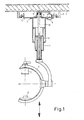
- FIG. 3 shows an X-ray examination device with a patient positioning table 20, which can be folded around a horizontal axis 2l by means of a drive motor 22, which acts on a toothed segment 23 connected to the table top 20.
- An x-ray aiming device 24 can be moved in the longitudinal direction of the table by means of the threaded spindle 11, which engages in a spindle nut 25 fastened to the aiming device 24, with the aid of an electric motor (not shown in more detail).
- the threaded spindle is fastened at least on one side to a bearing which is connected to the frame of the patient support table 20 via an elastic bearing support, as shown in FIG. 2.
- the displacement of the target device in the direction of compression i.e. perpendicular to the table top, can - as can be seen from Fig. 3 - with the help of an analog drive.
- the forces measured by the bearing support depend crucially on the position of the table top 20. They are minimal in the horizontal table top position shown in the drawing and maximum in the vertical position of the table top; in between they change with the sine of the swivel angle.
- the signal supplied by the strain gauge connected to the bearing support must be compared with a signal that changes sinusoidally with the swivel angle and that is taken, for example, from a sine potentiometer that is coupled to the drive 22 is.
- Fig. 4 shows part of a suitable drive.
- the motor power is transmitted via a pulley 30 to a shaft 3l, on which there is a helical gear 32, the flanks of which run at an angle ⁇ to the direction of the shaft.
- the helical gear 32 cooperates with a further helical gear 33, which is coupled to the toothed segment 23 (FIG. 3) in a manner not shown in detail.
- the helical gear 32 is supported on both sides in bearings l3, which are each connected to a part 34 fixed in the axial direction of the shaft 3l via the elastic bearing supports l2.
- a helical force acts on the helical spur gears 32 in the direction of the shaft 3l, the size of which depends on the torque and the direction of which depends on the direction of rotation. It can be detected with the sensors attached to the bearing supports l2 - preferably strain gauges.
- FIG. 5 shows a control circuit for influencing the drive motor.
- the forces acting on the device part cause a deformation of the elastic bearing support and thereby a change in the resistance of the strain gauge.
- This change in resistance is converted in a resistance measuring bridge 45 into an electrical voltage, which is amplified by an amplifier 40 and fed to the one input of a comparator 4l.
- the Voltage at the other input must be constant. If, however, an additional device, for example a 100 mm film camera 42, is to be connected to the device 5 to 7, the weight changed thereby must be taken into account by changing the reference voltage.
- the load that can be changed in a device according to FIG. 3 as a function of the pivoting position of the device can be taken into account with the aid of a further potentiometer 47, the tap of which is coupled to the transfer drive.
- the patient weight, which is important when moving the patient support plate, can be taken into account, for example, by tapping the voltage at the comparative input of the comparator 4l from the tap of a potentiometer 48, which corresponds to the patient weight - e.g. by a keyboard 49 - is adjustable.
- the three potentiometers 44, 47 and 48 can optionally also be connected in cascade.
Landscapes
- Life Sciences & Earth Sciences (AREA)
- Health & Medical Sciences (AREA)
- Engineering & Computer Science (AREA)
- Medical Informatics (AREA)
- Physics & Mathematics (AREA)
- Radiology & Medical Imaging (AREA)
- Heart & Thoracic Surgery (AREA)
- High Energy & Nuclear Physics (AREA)
- Veterinary Medicine (AREA)
- Nuclear Medicine, Radiotherapy & Molecular Imaging (AREA)
- Optics & Photonics (AREA)
- Pathology (AREA)
- Public Health (AREA)
- Biomedical Technology (AREA)
- Biophysics (AREA)
- Molecular Biology (AREA)
- Surgery (AREA)
- Animal Behavior & Ethology (AREA)
- General Health & Medical Sciences (AREA)
- General Physics & Mathematics (AREA)
- Automation & Control Theory (AREA)
- Apparatus For Radiation Diagnosis (AREA)
- Analysing Materials By The Use Of Radiation (AREA)
- X-Ray Techniques (AREA)
Applications Claiming Priority (2)
| Application Number | Priority Date | Filing Date | Title |
|---|---|---|---|
| DE19863614295 DE3614295A1 (de) | 1986-04-26 | 1986-04-26 | Roentgengeraet mit antrieb eines geraeteteils |
| DE3614295 | 1986-04-26 |
Publications (2)
| Publication Number | Publication Date |
|---|---|
| EP0244011A2 true EP0244011A2 (fr) | 1987-11-04 |
| EP0244011A3 EP0244011A3 (fr) | 1988-02-10 |
Family
ID=6299675
Family Applications (1)
| Application Number | Title | Priority Date | Filing Date |
|---|---|---|---|
| EP87200718A Ceased EP0244011A3 (fr) | 1986-04-26 | 1987-04-16 | Appareil de radiologie pourvu d'une partie motorisée |
Country Status (4)
| Country | Link |
|---|---|
| US (1) | US4868845A (fr) |
| EP (1) | EP0244011A3 (fr) |
| JP (1) | JPS62254738A (fr) |
| DE (1) | DE3614295A1 (fr) |
Cited By (2)
| Publication number | Priority date | Publication date | Assignee | Title |
|---|---|---|---|---|
| FR2665098A1 (fr) * | 1990-07-30 | 1992-01-31 | Poulain Michel | Plan de travail suspendu. |
| EP2060232A1 (fr) * | 2005-04-11 | 2009-05-20 | Gendex Corporation | Caractéristiques de positionnement structurelles et de patient d'un systeme a rayons x |
Families Citing this family (29)
| Publication number | Priority date | Publication date | Assignee | Title |
|---|---|---|---|---|
| US4955046A (en) * | 1989-04-17 | 1990-09-04 | Siczek Aldona A | C-arm for X-ray diagnostic examination |
| DE8905588U1 (fr) * | 1989-05-03 | 1990-09-13 | Siemens Ag, 1000 Berlin Und 8000 Muenchen, De | |
| JPH0683708B2 (ja) * | 1989-11-17 | 1994-10-26 | 株式会社東芝 | X線撮影装置 |
| US5052036A (en) * | 1990-04-02 | 1991-09-24 | Grady John K | X-ray stand with laterally inclined rotation axis |
| US5086447A (en) * | 1990-06-04 | 1992-02-04 | Siczek Aldona A | Overhead X-ray apparatus for imaging in bi-plane configuration |
| US5148454A (en) * | 1991-08-27 | 1992-09-15 | Coffman George W | Apparatus for conducting cranial X-ray tomography and radiography |
| US5405117A (en) * | 1993-10-27 | 1995-04-11 | Davis; Greig S. | Gliding ceiling monitor support assembly |
| US5475730A (en) * | 1994-08-24 | 1995-12-12 | John K. Grady | Telescoping X-ray support arms |
| US5960054A (en) * | 1997-11-26 | 1999-09-28 | Picker International, Inc. | Angiographic system incorporating a computerized tomographic (CT) scanner |
| US6131690A (en) * | 1998-05-29 | 2000-10-17 | Galando; John | Motorized support for imaging means |
| US6374937B1 (en) * | 1998-05-29 | 2002-04-23 | John Galando | Motorized support for imaging means and methods of manufacture and use thereof |
| DE10043473A1 (de) * | 2000-09-04 | 2001-11-08 | Siemens Ag | Vorrichtung zur Positionsermittlung |
| DE10139343B4 (de) * | 2001-08-10 | 2006-01-19 | Ziehm Imaging Gmbh | Verfahren und Vorrichtung zur Bestimmung der Position des Fokuspunktes einer Röntgenstrahlenquelle |
| US20050220273A1 (en) * | 2004-04-02 | 2005-10-06 | Friedrich Ueffinger | Digital radiography system |
| JP4571510B2 (ja) * | 2005-01-07 | 2010-10-27 | ジーイー・メディカル・システムズ・グローバル・テクノロジー・カンパニー・エルエルシー | 医療診断装置用撮影テーブル及び医療診断装置 |
| DE102005020811A1 (de) * | 2005-05-04 | 2006-11-09 | Schaeffler Kg | Linearwälzlager |
| US7377475B1 (en) * | 2005-07-22 | 2008-05-27 | Rodovaldo Lopez | Television mount assembly |
| US7300205B2 (en) * | 2005-11-25 | 2007-11-27 | Grady John K | Angio capable portable x-ray fluoroscopy unit with sliding C-arm and variable pivot |
| US20070140436A1 (en) * | 2005-12-15 | 2007-06-21 | Eastman Kodak Company | Dual telescoping support member digital radiography imaging system |
| FR2895899B1 (fr) * | 2006-01-06 | 2008-12-05 | Designers Developers Distribut | Systeme d'imagerie medicale. |
| US7793907B2 (en) * | 2007-04-20 | 2010-09-14 | Robert Woodward | Monitor suspension device and method of use |
| JP2010221003A (ja) * | 2009-02-26 | 2010-10-07 | Fujifilm Corp | 放射線撮影装置 |
| US8430564B2 (en) * | 2011-02-28 | 2013-04-30 | General Electric Company | Sliding counterbalanced C-arm positioning devices and methods for using such devices |
| US8967573B2 (en) * | 2013-03-14 | 2015-03-03 | Dental Equipment, Llc | Modular, bypass track and carriage system for overhead-mounted lights and other devices |
| US9307946B2 (en) | 2013-03-14 | 2016-04-12 | Dental Imaging Technologies Corporation | Ceiling mounted medical imaging system |
| US9897095B2 (en) | 2015-05-01 | 2018-02-20 | Hunter Fan Company | Ceiling fan kit and method of mounting |
| US10849582B2 (en) * | 2016-08-29 | 2020-12-01 | Shimadzu Corporation | Holding mechanism for X-ray imaging apparatus and X-ray imaging apparatus |
| EP3396226B1 (fr) * | 2017-04-27 | 2023-08-23 | Advanced Digital Broadcast S.A. | Procédé et dispositif permettant de régler la position d'un écran d'affichage |
| DE102018109582A1 (de) * | 2018-04-20 | 2019-10-24 | Carl Zeiss Meditec Ag | Röntgenstrahlungsgerät für medizinische Anwendungen |
Citations (5)
| Publication number | Priority date | Publication date | Assignee | Title |
|---|---|---|---|---|
| FR2194402A1 (fr) * | 1972-08-05 | 1974-03-01 | Radiologie Cie Gle | |
| FR2194401A1 (fr) * | 1972-08-04 | 1974-03-01 | Radiologie Cie Gle | |
| US4210815A (en) * | 1978-11-20 | 1980-07-01 | General Electric Company | X-ray apparatus servo system |
| EP0018936A1 (fr) * | 1979-03-22 | 1980-11-12 | Lechler, Gerhard, Dr.Ing. | Dispositif de mesure de la force pour paliers à roulement |
| EP0144670A2 (fr) * | 1983-11-03 | 1985-06-19 | Siemens Aktiengesellschaft | Appareil de radiodiagnostic comprenant des filtres de rayonnement |
Family Cites Families (4)
| Publication number | Priority date | Publication date | Assignee | Title |
|---|---|---|---|---|
| US3556455A (en) * | 1968-06-24 | 1971-01-19 | Fred Storm Ind Designs Inc | Overhead equipment control apparatus for operating rooms |
| DE2104509B2 (de) * | 1971-02-01 | 1973-07-12 | Roentgenuntersuchungsgeraet mit einem motorisch verstellbaren geraeteteil | |
| DE2361985A1 (de) * | 1973-12-13 | 1975-06-19 | Philips Patentverwaltung | Motorantrieb zur verschiebung eines geraeteteils an einem roentgenuntersuchungsgeraet |
| US4677273A (en) * | 1986-02-12 | 1987-06-30 | Leybold-Heraeus Gmbh | Electron beam welding apparatus |
-
1986
- 1986-04-26 DE DE19863614295 patent/DE3614295A1/de not_active Withdrawn
-
1987
- 1987-04-16 EP EP87200718A patent/EP0244011A3/fr not_active Ceased
- 1987-04-23 JP JP62098748A patent/JPS62254738A/ja active Pending
- 1987-04-27 US US07/043,017 patent/US4868845A/en not_active Expired - Fee Related
Patent Citations (5)
| Publication number | Priority date | Publication date | Assignee | Title |
|---|---|---|---|---|
| FR2194401A1 (fr) * | 1972-08-04 | 1974-03-01 | Radiologie Cie Gle | |
| FR2194402A1 (fr) * | 1972-08-05 | 1974-03-01 | Radiologie Cie Gle | |
| US4210815A (en) * | 1978-11-20 | 1980-07-01 | General Electric Company | X-ray apparatus servo system |
| EP0018936A1 (fr) * | 1979-03-22 | 1980-11-12 | Lechler, Gerhard, Dr.Ing. | Dispositif de mesure de la force pour paliers à roulement |
| EP0144670A2 (fr) * | 1983-11-03 | 1985-06-19 | Siemens Aktiengesellschaft | Appareil de radiodiagnostic comprenant des filtres de rayonnement |
Cited By (2)
| Publication number | Priority date | Publication date | Assignee | Title |
|---|---|---|---|---|
| FR2665098A1 (fr) * | 1990-07-30 | 1992-01-31 | Poulain Michel | Plan de travail suspendu. |
| EP2060232A1 (fr) * | 2005-04-11 | 2009-05-20 | Gendex Corporation | Caractéristiques de positionnement structurelles et de patient d'un systeme a rayons x |
Also Published As
| Publication number | Publication date |
|---|---|
| JPS62254738A (ja) | 1987-11-06 |
| EP0244011A3 (fr) | 1988-02-10 |
| US4868845A (en) | 1989-09-19 |
| DE3614295A1 (de) | 1987-10-29 |
Similar Documents
| Publication | Publication Date | Title |
|---|---|---|
| EP0244011A2 (fr) | Appareil de radiologie pourvu d'une partie motorisée | |
| EP0160749B1 (fr) | Appareil pour examen radiologique | |
| DE2831058C2 (de) | Röntgenuntersuchungsgerät mit einem um eine horizontale Achse schwenkbaren Patientenlagerungstisch | |
| EP0066272B1 (fr) | Dispositif de support pour patient à couchette basculante | |
| DE3527906C2 (fr) | ||
| DE3541043A1 (de) | Hoehenmessgeraet | |
| EP0200987B1 (fr) | Appareil de radiologie comportant un système d'équilibrage à ressort | |
| EP1251380A2 (fr) | Statif pour un microscope d'opération | |
| EP3300229A1 (fr) | Dispositif de levage et de rotation | |
| DE3236116C2 (fr) | ||
| DE3916428C2 (fr) | ||
| EP0082386A1 (fr) | Dispositif d'entraînement pour manipulateur | |
| DE2742642C3 (de) | Anordnung zum Gewichtsausgleich | |
| DE1605363C3 (de) | Vorrichtung an einem zur Messung, Registrierung und/oder Korrektur der Lage von Gleisen dienenden Fahrzeug, insbesondere Gleisrichtmaschine | |
| DE2404467B2 (de) | Zeichenmaschine | |
| DE3227258C2 (fr) | ||
| EP0569914A1 (fr) | Dispositif pour soulever un avion | |
| DE2739934A1 (de) | Roentgenuntersuchungsgeraet | |
| DE4140202A1 (de) | Scheren-hebebuehnen, hubtisch o. dgl. | |
| DE4400697C2 (de) | Medizinisches Gerät für Diagnose- und Behandlungszwecke | |
| DE4423359A1 (de) | Chirurgische Röntgendiagnostikeinrichtung | |
| DE2124739C3 (de) | Hebekran mit längen- und neigungsverstellbarem Kranbaum und einer Überlastsicherung | |
| DE3334756A1 (de) | Kraftvergleichsvorrichtung mit dreikraeftegleichgewicht, vorzugsweise fuer einen messumformer | |
| DE202020105612U1 (de) | Bodenstativ | |
| EP0547377A2 (fr) | Support pour appareil à rayons X |
Legal Events
| Date | Code | Title | Description |
|---|---|---|---|
| PUAI | Public reference made under article 153(3) epc to a published international application that has entered the european phase |
Free format text: ORIGINAL CODE: 0009012 |
|
| AK | Designated contracting states |
Kind code of ref document: A2 Designated state(s): DE FR GB IT |
|
| PUAL | Search report despatched |
Free format text: ORIGINAL CODE: 0009013 |
|
| AK | Designated contracting states |
Kind code of ref document: A3 Designated state(s): DE FR GB IT |
|
| 17P | Request for examination filed |
Effective date: 19880729 |
|
| 17Q | First examination report despatched |
Effective date: 19910927 |
|
| STAA | Information on the status of an ep patent application or granted ep patent |
Free format text: STATUS: THE APPLICATION HAS BEEN REFUSED |
|
| 18R | Application refused |
Effective date: 19920314 |
|
| RIN1 | Information on inventor provided before grant (corrected) |
Inventor name: KOROPP, NORBERT |