EP0243793B1 - Hydraulischer Zusammenbau für die Wasserkühlung von elektrischen Mehrchip-Modulen - Google Patents
Hydraulischer Zusammenbau für die Wasserkühlung von elektrischen Mehrchip-Modulen Download PDFInfo
- Publication number
- EP0243793B1 EP0243793B1 EP87105555A EP87105555A EP0243793B1 EP 0243793 B1 EP0243793 B1 EP 0243793B1 EP 87105555 A EP87105555 A EP 87105555A EP 87105555 A EP87105555 A EP 87105555A EP 0243793 B1 EP0243793 B1 EP 0243793B1
- Authority
- EP
- European Patent Office
- Prior art keywords
- appendages
- apertures
- wax
- section
- coolant
- Prior art date
- Legal status (The legal status is an assumption and is not a legal conclusion. Google has not performed a legal analysis and makes no representation as to the accuracy of the status listed.)
- Expired - Lifetime
Links
Images


Classifications
-
- H10W40/772—
Definitions
- This invention relates to cooling systems for electric circuit chips and, more particularly, to a manifold having flexible connectors for mating with a plurality of individual chip heat exchangers for the cooling of electric circuits.
- Electric circuits are fabricated frquently in the form of chips.
- Complex electronic systems are constructed of many such chips which are disposed on a common substrate, such an arrangement of the chips being referred to as a module.
- a module may have as many as one hundred or more chips.
- a set of the modules may be electrically interconnected to provide still larger systems.
- High power chips can now be cooled by use of forced-convection silicon heat exchangers which are thermally attached to respective ones of the chips, as is described in the following article: D. B. Tuckerman and R. F. W. Pease, "High Performance Heat Sinking for VLSI", IEEE Electron Device Letters EDL-2, Page 126 (1981);
- a source of cooled liquid such as water is connected between input and output ports of the heat exchangers to pass the water through the heat exchangers for removal of heat from the circuit chips.
- An array of the heat exchangers connected to respective ones of the chips is an effective means for maintaining proper operating temperature for an entire module of electric circuits. All of the heat exchangers are to be connected to the source of cooling liquid for removal of heat from the module.
- the chips and the heat exchangers mounted thereon may be positioned in two dimensions with a pitch of less than a centimeter, and each heat exchanger has two ports (input and output) which are to be connected to the water source.
- a particular aspect of the problem is manifested in the maintenance of tolerances among positions of the ports to allow for an interfacing with a suitable connection device.
- a further aspect of the problem is the necessity for stress relief because of the specific materials employed in the construction of the electric circuits.
- the substrate upon which the chips are mounted may be fabricated of ceramic, and semiconductor circuitry within the chips may be fabricated of silicon.
- Both the ceramic and the silicon are rigid materials which might introduce excessive stress to soft metallic ball contacts located between the chips and the substrate for making electrical connection between circuits of the chips and electrical conductors located in the substrate. Therefore, there is a need for mechanically decoupling the source of cooling water from the heat exchangers to prevent a buildup of any additional stresses which might be introduced by the water source.
- EP -A-0 168 677 and EP-A-0 196 054 both describe a manifold for conducting coolant to a plurality of electrical circuit chips having cooling devices connected thereto.
- Each of the manifolds described has a coolant conduit and a set of apertures which communicate with the conduit, and a set of hollow flexible appendages connected to the body at the apertures and extending from the body for conduction of coolant between the body and the cooling devices.
- Each of the appendages is distensible to allow connection with ports of the cooling devices.
- the present invention relates to a manifold for conducting coolant to a plurality of electric circuit chips having cooling devices connected thereto, the manifold comprising a solid body having a first and a second coolant conduit means and a first set of apertures communicating with the first conduit means and a second set of apertures communicating with the second conduit means, and a first set and a second set of flexible hollow appendages connected to the body respectively at the first and the second sets of apertures and extending from the body for conduction of coolant between the cooling devices and the first and the second conduit means of the body, each of the appendages being distensible to allow connection with ports of the cooling devices.
- the first conduit means and the second conduit means are separate from each other for maintaining separate flows of the coolant to and from each of said cooling devices, two of the appendages are connectable with each of said cooling devices, one of the two appendages serving as an inlet coolant conduit and the other of the two appendages serving as an outlet coolant conduit, and the two appendages being mounted coaxially of each other with one appendage being outside of and surrounding the other inner appendage.
- the manifold is characterised in that the body further comprises three sections extending transversely to the appendages and being arranged alongside one another to define the first and the second conduit means including fluid conduction passages therein.
- the first and the second sets of apertures are disposed in separate ones of the sections spaced apart from each other to permit connection of the first and the second sets of appendages independently of each other to their respective first and second sets of apertures.
- a first one of the body sections and a second one of the body sections are secured together, the first conduit means being formed within the first section, and the first set of apertures being formed in the second section.
- a third one of the body sections is secured to the second section so that the second set of apertures is in registration with the apertures of the second section.
- the inner appendage of the two appendages for connecting to a cooling device connects with an aperture of the second section and the outer appendage of the two appendages connects with an aperture of the third section.
- the second section has sidewalls contacting the third section for spacing the first set of apertures away from the cooling devices at a distance greater than the spacing of the second set of apertures from the cooling devices, the inner one of the two appendages being longer than the outer one of the two appendages to extend over the greater distance from the cooling devices to the first set of apertures.
- the present invention also relates to a method of fabricating a manifold for conducting coolant to a plurality of electrical circuit chips having cooling devices connected thereto.
- the method comprises forming a solid body having a coolant conduit with a set of apertures therein, the body having walls defining an open cavity located on the outside of the body and communicating with the apertures, filling the cavity with wax, milling out bellows shaped passages through the wax and the body to form a set of flexible hollow bellows shaped appendages, and removing the wax.
- the rigid body of the manifold may have a linear shape to make contact with a line of water inlets or a line of water outlets in a row of heat exchangers.
- the body would be constructed of two parts arranged in pairs, with one body part and its associated appendages servicing the inlet ports and a second body part and its associated appendages servicing the outlet ports of the row of heat exchangers.
- a manifold may be formed to service a rectangular array of heat exchangers, in which case the manifold comprises a rigid body of rectangular shape with a rectangular array of flexible hollow appendages depending therefrom to contact ports from a rectangular array of heat exchangers.
- a feature in this embodiment of the invention is the combination of a single inlet appendage and a single outlet appendage into a composite coaxial appendage.
- the construction of the heat exchangers is modified to provide for coaxial inlets and outlets.
- the solid body portion of a linear manifold is formed of two sections which are held together to contain the water. One of the sections contains fluid conduction channels machined therein. The other section has apertures in which are mounted the hollow appendages.
- the solid body portion of a rectangular manifold comprises three sections, namely, a first section with the fluid conduction channels, a second section having apertures for holding the inner of the coaxial appendages, and a third section secured to the second section and having apertures for holding the outer of the coaxial appendages.
- a feature in the manufacture of the manifold is the construction of the hollow flexible appendages in the form of bellows of thin plastic material whereby the mouths of the bellows are movable readily in three orthogonal directions corresponding to the x, y, and z directions of the axes of an xyz coordinate system. This permits the mouths of the bellows to be positioned independently for mating with the ports of the heat exchangers.
- the flexibility of the bellows construction also serves to isolate mechanically the heat exchanger and chip from a source of liquid coolant, and thereby provide stress relief to the ball contacts between the chips and a substrate supporting the chips.
- the plastic bellow material is substantially impervious to water and other cooling fluids which may be employed.
- the water-tight integrity of the manifold is attained by forming the appendages integrally with a section of the solid body by a casting technique which prevents the development of any voids through which liquid might leak and contaminate electrical components of the module.
- the casting of the appendages is accomplished by a lost wax technique wherein an apertured section of the solid body is filled with wax, the bellows forms of the appendages are machined in the wax, and then the plastic material is deposited in vacuum by chemical vapor deposition (CVD) upon the wax and the apertured section of the solid body. Excess plastic material, such as webbing between mouths of the bellows, may be trimmed away. Then the wax is melted and poured off to leave a completed assembly of appendages secured to an apertured section of the solid body.
- CVD chemical vapor deposition
- the use of the CVD process in the formation of the appendages insures a conformal adhesion of the appendages to the solid body for water-tight operation of the manifold of the invention.
- an electronic circuit module 20 comprises an array of circuit chips 22 supported upon a common substrate 24 and interconnected electrically by well known conductors (not shown).
- the array of chips is a rectangular array having rows and columns of the chips 22, it being understood that the invention applies also to other forms of arrays.
- a set of silicon heat exchangers 26 is provided for cooling the chips 22, one heat exchanger 26 being mounted by conventional means on each chip 22 for removal of heat therefrom.
- the heat exchangers 26 are operative with liquid coolant provided by a chiller 28.
- the coolant is carried from the chiller 28 and distributed among the heat exchangers 26 by a manifold 30.
- each heat exchanger 26 is understood to be provided with separate, spaced-apart coolant ports, namely, a coolant inlet 32 and a coolant outlet 34.
- the manifold 30 is constructed accordingly of two parts, namely, an inlet manifold 36 which brings coolant from the chiller 28 to the inlets 32 of the heat exchangers 26, and an outlet manifold 38 which returns the coolant from the outlets 34 of the heat exchangers 26 to the chiller 28.
- the inlet and the outlet ports in each heat exchanger are formed coaxially, and the manifold is modified to mate with the coaxial ports, as will be described hereinafter.
- the inlet manifold 36 and the outlet manifold 38 are constructed in the same fashion.
- the manifolds 36 and 38 each embody the same features of the invention, and are constructed by use of a manufacturing process employing aspects of the invention. Accordingly, the ensuing description of the manifold 30 is directed to the inlet manifold 36, it being understood that the description applies equally well to the outlet manifold 38.
- the inlet manifold 36 comprises a solid body 40 containing a coolant conduction channel 42, and a set of flexible hollow appendages 44 which extend from the body 40 and serve as conduits for conducting liquid coolant from the channel 42 to the inlets 32 of respective ones of the heat exchangers 26.
- Each appendage 44 has the shape of a bellows with accordion folds 46 which allow for extension and retraction of a mouth 48 of the appendage 44, as well as for a sidewise displacement of the mouth 48, to facilitate alignment and connection of the mouth 48 with an inlet 32.
- the inlet manifold 36 is formed in the configuration of a set of branches 50 extending from a stem 52, this configuration providing for a distribution of the coolant among the rows of the heat exchangers 26 to which the respective branches 50 are connected by their appendages 44.
- the body 40 is constructed of a top section 54 and a bottom section 56 which are held together by bolts 58 with a gasket 60 disposed between the sections 54 and 56 to insure a water-tight fit.
- the coolant conduction channel 42 is machined into the top section 54, prior to connection of the top section 54 to the bottom section 56.
- the bottom section 56 includes a set of apertures 62 to which are secured the appendages 44. Upon connection of the top section 54 to the bottom section 56, the apertures 62 align with the channel 42 so as to form a continuous coolant path from the stem 52 to the mouths 48 of the appendages 44.
- the bottom section 56 is formed with sidewalls 64 which define a central chamber 66 for holding wax to be used in the construction of the appendages 44 in accordance with a manufacturing process of the invention, to be described hereinafter.
- the sidewalls 64 also serve to provide rigidity to the inlet manifold 36, as well as to position the inlet manifold 36 above the array of heat exchangers 26.
- Fig. 5 shows manufacturing steps, in accordance with the invention, for fabricating the bottom section 56 of the manifold body 40 in a water-tight union with a set of appendages 44 joining the body 40 at the apertures 62.
- the bottom section 56 includes the apertures 62 and the sidewalls 64.
- the bottom section 56 is formed first from an easily machinable block of metal such as aluminum or other light-weight material which is easily machinable or moldable including an injection moldable plastic.
- the aluminum may be sandblasted to improve adhesion of the plastic material of the appendage to be secured thereto.
- a readily machinable wax, paraffin is poured into the chamber 66, and is solidified by cooling.
- the manufacturing procedure continues with a milling of the wax.
- straight bores are milled in registration with the apertures 62.
- accordion folds are milled into the sides of the bores to provide a bellows surface 68 communicating with each of the apertures 62.
- the bottoms of the bores are chamfered at 70 to provide skirt shapes to the mouths 48.
- a fluting is provided to the surface of the wax at 72 to enable the subsequent formation of a pleated membrane which interconnects the mouths 48 of the appendages 44.
- the next step is the deposition of a plastic material, by a process of chemical vapor deposition, on all exposed surfaces of the wax and exposed surfaces of the bottom section 56, including the apertures 62.
- This is accomplished in a vacuum chamber by use of a source 74 which ejects particles of plastic material in the form of a vapor which permeates all parts of the mold comprising the wax and the bottom section 56.
- the particles nucleate upon contact with the wax and the metal of the bottom section 56 to form an impervious skin of plastic material.
- the CVD process insures that the plastic particles impinge upon all portions of the foregoing surfaces, including blind portions thereof, thereby providing a conformal water-tight coating. It is noted that the presence of the plastic material on the upper surface of the bottom section 56 mates with the bottom surface of the top section 54, thereby closing off the open side of the channels 42 upon a joining of the top section 54 to the bottom section 56.
- the bottom section 56 does not come in contact with liquid coolant, but serves only to support the assembly of plastic appendages, which might include as many as one hundred appendages 44. Indeed, water-tight integrity can be obtained even without a water-tight joint between the material of the bottom section 56 and the plastic material of the appendages 44.
- the plastic bellows construction of the appendages 44 is sufficiently flexible to provide a further advantage, namely, mechanical isolation of stress from the heat-exchangers, chips 22 and substrate 24, which stress may be communicated from the chiller 28 to the manifold 30.
- a suitable plastic material having the desired characteristics of flexibility and being chemically inert to common coolants, while allowing deposition by the CVD process is produced commercially by UNION CARBIDE under the name of Parylene, this being a dimer of Di-Para-Xylylene converted by vaporisation to a monomer comprising para-xylylene.
- This monomer is pyrolized at 680 degrees Celsius into a polymer poly-para-xylylene.
- the nucleation is enhanced by chilling the body section 56 and the wax therein by means of a conventional cold finger and chiller (not shown) to a temperature, for example, five degrees Celsius in the case of the Parylene.
- the plastic material can be deposited to a thickness ranging from a very small fraction of a millimeter to a small fraction of a millimeter (a fraction of mil up to several mils). Thicknesses of 0.064 and 0.2 millimeters have been employed, the latter providing a stiffer appendage 44.
- the process continues with the removal of the wax. This is accomplished by drilling a hole 76 in a sidewall 64, heating the wax, and pouring out the wax via the hole 76. If desired, a thorough removal of the wax can be accomplished by cleaning the interior surfaces of the body section 56 with a solvent such as 1-1-1,trichloroethane. After removal of the wax. there remains the plastic appendages 44 produced by the deposition of the plastic along the bellows surface 68 of the wax, and an articulated membrane 78 which joins the mouths 48 of the appendages 44 and is formed by the deposition of the plastic upon the fluted surface 72 of the wax. Alternatively, the fluted surface 72 of the wax with the plastic coating thereon can be removed by machining, prior to removal of the wax.
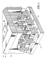
- a coolant delivery manifold 82 of the invention wherein the heat exchangers are formed with coaxially arranged inlet and outlet ports, and a coaxial assembly 84 of hollow appendages connects the heat-exchanger ports to the manifold 82.
- the manifold 82 comprises three sections, a first section formed as a rectangular or square cover plate 86 having a system 88 of fluid conduction channels therein, a second section formed as an inlet body section 90 having fluid conduction apertures 92 and sidewalls 94, and a third section at the bottom of the manifold 82 formed as an outlet body section 96 having enlarged fluid conduction apertures 98 and sidewalls 100.
- the inlet body section 90 and the outlet body section 96 have the same form, except for a difference in aperture size and overall dimensions, the outlet body section 96 being shown in detail in Figs 7 - 8.
- the outlet body section 96 is shown as comprising a square array of thirty six apertures 98, it being understood that other rectangular arrays can be employed.
- the channel system 88 of the cover plate 86 is shown in detail in Fig 9.
- Each appendage assembly 84 comprises a relatively long and narrow inlet appendage 102 secured to an aperture 92, and a relatively short and wide outlet appendage 104 secured to an aperture 98.
- the appendage 102 passes through the appendage 104 to connect with an inlet port 106 of a heat exchanger 108, while the appendage 104 connects with an outlet port 110 of the heat exchanger 108.
- the two ports 106 and 110 are coaxial, with the inlet port 106 being disposed within the outlet port 110.
- the upper ends of the outlet appendages 104 open, via the apertures 98, into a chamber 112 formed by the sidewalls 94 and floor portions 114 and 116, respectively, of the inlet body section 90 and the outlet body section 96.
- the chamber 112 opens via a port 118 in a sidewall 94 to a return conduit to the chiller 28 (Fig. 2).
- the upper ends of the inlet appendages 102 open, via the apertures 92, into the channels of the system 88.
- the channel system communicates via a port 120 to a supply line of the chiller 28 (Fig. 2) for reception of coolant from the chiller 28.
- the cover plate 86 and the body sections 90 and 96 are connected together by water-tight seals (not shown) and held in position by bolts (not shown) threaded through holes 122 in the body sections 90 and 96.
- the inlet body section 90 with its relatively long inlet appendages 102, and the outlet body section 96 with its outlet appendages 104 are constructed each in accordance with the process disclosed in Fig. 5.
- the sidewalls 94 of the inlet body section 90 are taller than the sidewalls 100 of the outlet body section 96, the increased height of the sidewalls 94 providing a wax-holding chamber large enough to accommodate the extra length of the inlet appendages 102.
- construction of the manifold 92 continues with insertion of the inlet appendages 102 into the outlet appendages 104, followed by a securing of the cover plate 86 and the outlet body section 96 to the inlet body section 90.
- the appendages 102 and 104 may be secured to the ports 106 and 110 of a heat exchanger 108 with epoxy glue, this providing sufficient strength because of the relatively low coolant pressure employed, typically less than a few thousand pascals (a few pounds per square inch). This completes construction of the coaxial manifold.
- Figs. 10 and 11 show alternative embodiments of wax molds suitable for construction of the flexible hollow appendages for conduction of coolant to a heat exchanger.
- the accordion folds are cut with a cutter 124, shown by way of example in the Figure, directly into the sides of the mold in a direction perpendicular to a central axis of the mold.
- the cutter 124 is driven by a numerically controlled milling machine (not shown).
- an accordion fold is cut as a reentrant circular trough in a direction parallel to a central axis of the mold. Both types of folds provide the requisite flexibility to the appendages. Also shown in Fig.
- a skirt region 126A composed of circular zones 128A, 130A, 132A and 134A wherein the surfaces are inclined respectively at angles of 45, 5, 0 and 45 degrees. This facilitates emplacement of the mouth of an appendage on a port of a heat exchanger.
- the wax mold is provided with a skirt region 126B composed of circular zones 128B, 130B, 132B and 134B wherein the surfaces are inclined respectively at angles of 45, 5, 0 and 45 degrees.
- the foregoing manifold construction of the invention is particularly advantageous because the flexibility of the coolant conduit appendages allows for positioning of the heat exchangers on their respective circuit chips independently of various differences in orientation which may be present. Thus, there is no requirement that all heat exchangers must be aligned with each other. Each heat exchanger may be placed in intimate thermal contact with the corresponding circuit chip. Any differences in orientation of the heat exchangers is readily accommodated by the flexibility of the appendages.
- the fabrication of the accordion folds by means of the lost wax process and by chemical vapor deposition of the plastic material allows for conformal adhesion of the plastic material to the solid body portion of the manifold for water-tight fit.
Landscapes
- Cooling Or The Like Of Semiconductors Or Solid State Devices (AREA)
- Heat-Exchange Devices With Radiators And Conduit Assemblies (AREA)
- Details Of Heat-Exchange And Heat-Transfer (AREA)
Claims (5)
- Verteiler (82) zum Leiten eines Kühlmittels an eine Mehrzahl von Chips (24) für elektrische Schaltungen, mit ihnen angefügten Kühleinrichtungen (108), wobei der Verteiler aufweist:
einen festen Körper mit einem ersten (88) und einem zweiten (94) Kühlmittelleitungsmittel und mit einem ersten Schritt von Öffnungen (92), die mit dem ersten Leitungsmittel kommunizieren und mit einem zweiten Satz von Öffnungen (98), die mit dem zweiten Leitungsmittel kommunizieren und einen ersten Satz (102) und einen zweiten Satz (104) flexibler hohler Fortsätze, die mit dem Körper jeweils bei den ersten und den zweiten Sätzen von Öffnungen verbunden sind und sich von dem Körper erstrecken, um ein Kühlmittel zwischen den Kühleinrichtungen und den ersten und den zweiten Leitungsmitteln des Körpers zu leiten, wobei jeder der Fortsätze dehnbar ist, um eine Verbindung mit Anschlüssen der Kühleinrichtungen zu ermöglichen,
wobei das erste Leitungsmittel und das zweite Leitungsmittel voneinander getrennt sind, um getrennte Flüsse des Kühlmittels zu jeder der Kühleinrichtungen hin und von dieser fort aufrechtzuerhalten,
zwei der Fortsätze mit jeder der Kühleinrichtungen verbunden werden können, wobei einer der zwei Fortsätze als eine Einlaß-Kühlmittelleitung dient und der andere der zwei Fortsätze als eine Auslaß-Kühlleitung dient und
die zwei Fortsätze koaxial zueinander angebracht sind, wobei sich ein Fortsatz außerhalb des anderen inneren Fortsatzes befindet und diesen umgibt,
dadurch gekennzeichnet, daß
der Körper ferner aufweist:
drei Teile (86, 90, 100), die sich quer zu den Fortsätzen erstrecken und nebeneinender angeordnet sind, um das erste und das zweite Leitungsmittel einschließlich darin befindlicher Fluidleitungsdurchgänge zu definieren,
wobei die ersten (92) und zweiten (98) Sätze von Öffnungen in getrennten der Teile (90, 100) zueinander beabstandet angeordnet sind, um eine Verbindung der ersten und zweiten Sätze von Fortsätzen voneinander unabhängig mit ihren entsprechenden ersten und zweiten Sätzen von Öffnungen zu ermöglichen,
der erste der Körperteile (86) und der zweite der Körperteile (90) aneinander befestigt sind, wobei das erste Leitungsmittel (88) innerhalb des ersten Teils (86) ausgebildet ist und der erste Satz von Öffnungen (92) in dem zweiten Teil (90) ausgebildet ist,
der dritte der Körperteile (100) an dem zweiten Teil (90) so befestigt ist, daß sich der zweite Satz von Öffnungen (98) in Ausrichtung mit den Öffnungen (92) des zweiten Teils befindet, der innere Fortsatz (102) der zwei Fortsätze zum Verbinden mit jeder Kühleinrichtung mit einer Öffnung (92) des zweiten Teils verbunden ist und der äußere Fortsatz (104) der zwei Fortsätze mit einer Öffnung (98) des dritten Teils verbunden ist und
der zweite Teil (90) Seitenwände (94) aufweist, welche den dritten Teil (100) berühren, um den ersten Satz von Öffnungen (92) in einem Abstand zu den Kühleinrichtungen anzuordnen, der größer ist, als der Abstand des zweiten Satzes von Öffnungen (98) zu den Kühleinrichtungen, wobei der innere (102) der zwei Fortsätze länger ist, als der äußere (104) der zwei Fortsätze, damit er sich über den größeren Abstand von den Kühleinrichtungen zu dem ersten Satz von Öffnungen erstreckt. - Verfahren zum Herstellen eines Verteilers (40) zum Leiten es Kühlmittels an eine Mehrzahl von Chips (24) für elektrische Schaltungen, mit ihnen angefügten Kühleinrichtungen (26), wobei das Verfahren folgendes umfaßt:
Ausbilden eines festen Körpers (54, 56), der eine Kühlmittelleitung (42) mit einem Satz von Öffnungen (62) in ihr aufweist, wobei der Körper Wände (64) besitzt, die einen offenen Hohlraum (66) definieren, der an der Außenseite des Körpers gelegen ist und mit den Öffnungen (62) kommuniziert,
Füllen des Hohlraums mit Wachs,
Ausarbeiten faltenbalgförmiger Durchgänge (68) durch das Wachs zu entsprechenden der Öffnungen (62),
Aufbringen eines Kunststoffs auf freien Oberflächen des Wachses und des Körpers durch Gasphasenabscheidung nach einem chemischen Verfahren, um einen Satz flexibler, hohler faltenbalgförmiger Fortsätze (44) auszubilden und
Entfernen des Wachses. - Verfahren nach Anspruch 2, bei welchem der Schritt des Aufbringens einen Schritt des Kühlens des Körpers und des Wachses zum Erhöhen einer Nukleierung des Kunststoffs umfaßt.
- Verfahren nach Anspruch 2, bei welchem der Schritt des Aufbringens einen Steg auf einer Frontoberfläche des Wachses zwischen Mündungen der Fortsätze zurückläßt, wobei das Verfahren ferner einen Schritt des Wegschneidens des Stegs vor dem Entfernen des Wachses umfaßt.
- Verfahren nach irgend einem der Ansprüche 2 bis 4, das ferner die folgenden Schritte umfaßt:
Ausbilden eines zweiten festen Körpers (96) mit einem zweiten Satz von Öffnungen (98) in ihn, die größer sind, als die erstgenannten Öffnungen (62) des erstgenannten Körpers (54, 56), wobei der zweite Körper (96) Wände besitzt, die einen offenen Hohlraum definieren, der an der Außenseite des zweiten Körpers (96) gelegen ist und mit dem zweiten Satz von Öffnungen (98) kommuniziert,
Füllen des Hohlraums des zweiten Körpers mit Wachs,
Ausarbeiten eines zweiten Satzes faltenbalgförmiger Durchgänge durch das Wachs zu entsprechenden des zweiten Satzes von Öffnungen,
Aufbringen eines Kunststoffs auf freien Oberflächen des Wachses in dem zweiten Hohlraum und auf freien Oberflächen des zweiten Körpers durch Gasphasenabscheidung nach chemischen Verfahren, um einen zweiten Satz flexibler, hohler faltenbalgförmiger Fortsätze (104) auszubilden,
Entfernen des Wachses aus dem Hohlraum des zweiten Körpers und
Einfügen des erstgenannten Satzes von Fortsätzen (44) in den zweiten Satz von Fortsätzen (104), um einen Satz koaxialer Fortsätze auszubilden.
Applications Claiming Priority (2)
| Application Number | Priority Date | Filing Date | Title |
|---|---|---|---|
| US06/858,135 US4759403A (en) | 1986-04-30 | 1986-04-30 | Hydraulic manifold for water cooling of multi-chip electric modules |
| US858135 | 1986-04-30 |
Publications (3)
| Publication Number | Publication Date |
|---|---|
| EP0243793A2 EP0243793A2 (de) | 1987-11-04 |
| EP0243793A3 EP0243793A3 (en) | 1988-01-07 |
| EP0243793B1 true EP0243793B1 (de) | 1992-07-15 |
Family
ID=25327573
Family Applications (1)
| Application Number | Title | Priority Date | Filing Date |
|---|---|---|---|
| EP87105555A Expired - Lifetime EP0243793B1 (de) | 1986-04-30 | 1987-04-14 | Hydraulischer Zusammenbau für die Wasserkühlung von elektrischen Mehrchip-Modulen |
Country Status (4)
| Country | Link |
|---|---|
| US (1) | US4759403A (de) |
| EP (1) | EP0243793B1 (de) |
| JP (1) | JPS62260347A (de) |
| DE (1) | DE3780346D1 (de) |
Families Citing this family (39)
| Publication number | Priority date | Publication date | Assignee | Title |
|---|---|---|---|---|
| US5029638A (en) * | 1989-07-24 | 1991-07-09 | Creare Incorporated | High heat flux compact heat exchanger having a permeable heat transfer element |
| US5145001A (en) * | 1989-07-24 | 1992-09-08 | Creare Inc. | High heat flux compact heat exchanger having a permeable heat transfer element |
| US5016090A (en) * | 1990-03-21 | 1991-05-14 | International Business Machines Corporation | Cross-hatch flow distribution and applications thereof |
| JPH06342990A (ja) * | 1991-02-04 | 1994-12-13 | Internatl Business Mach Corp <Ibm> | 統合冷却システム |
| US5228502A (en) * | 1991-09-04 | 1993-07-20 | International Business Machines Corporation | Cooling by use of multiple parallel convective surfaces |
| JP2852148B2 (ja) * | 1991-10-21 | 1999-01-27 | 日本電気株式会社 | 集積回路パッケージの冷却構造 |
| US5509468A (en) * | 1993-12-23 | 1996-04-23 | Storage Technology Corporation | Assembly for dissipating thermal energy contained in an electrical circuit element and associated method therefor |
| US6173760B1 (en) * | 1998-08-04 | 2001-01-16 | International Business Machines Corporation | Co-axial bellows liquid heatsink for high power module test |
| US6418748B1 (en) | 2001-03-22 | 2002-07-16 | Emmpak Foods, Inc. | Machinery cooling system |
| US6498725B2 (en) * | 2001-05-01 | 2002-12-24 | Mainstream Engineering Corporation | Method and two-phase spray cooling apparatus |
| US7100389B1 (en) * | 2002-07-16 | 2006-09-05 | Delta Design, Inc. | Apparatus and method having mechanical isolation arrangement for controlling the temperature of an electronic device under test |
| US8464781B2 (en) | 2002-11-01 | 2013-06-18 | Cooligy Inc. | Cooling systems incorporating heat exchangers and thermoelectric layers |
| US20040112571A1 (en) * | 2002-11-01 | 2004-06-17 | Cooligy, Inc. | Method and apparatus for efficient vertical fluid delivery for cooling a heat producing device |
| US7591302B1 (en) * | 2003-07-23 | 2009-09-22 | Cooligy Inc. | Pump and fan control concepts in a cooling system |
| US7013955B2 (en) * | 2003-07-28 | 2006-03-21 | Thermal Corp. | Flexible loop thermosyphon |
| US7870891B2 (en) * | 2004-05-29 | 2011-01-18 | Kilr-Chilr, Llc | Systems, devices and methods for regulating temperatures of tanks, containers and contents therein |
| US20060011326A1 (en) * | 2004-07-15 | 2006-01-19 | Yassour Yuval | Heat-exchanger device and cooling system |
| US20060096738A1 (en) * | 2004-11-05 | 2006-05-11 | Aavid Thermalloy, Llc | Liquid cold plate heat exchanger |
| US7353859B2 (en) * | 2004-11-24 | 2008-04-08 | General Electric Company | Heat sink with microchannel cooling for power devices |
| US7327024B2 (en) * | 2004-11-24 | 2008-02-05 | General Electric Company | Power module, and phase leg assembly |
| WO2006138655A2 (en) * | 2005-06-16 | 2006-12-28 | Delta Design, Inc. | Apparatus and method for controlling die force in a semiconductor device testing assembly |
| US7515418B2 (en) * | 2005-09-26 | 2009-04-07 | Curtiss-Wright Controls, Inc. | Adjustable height liquid cooler in liquid flow through plate |
| US7298618B2 (en) * | 2005-10-25 | 2007-11-20 | International Business Machines Corporation | Cooling apparatuses and methods employing discrete cold plates compliantly coupled between a common manifold and electronics components of an assembly to be cooled |
| US20080013278A1 (en) * | 2006-06-30 | 2008-01-17 | Fredric Landry | Reservoir for liquid cooling systems used to provide make-up fluid and trap gas bubbles |
| US20080175951A1 (en) | 2007-01-23 | 2008-07-24 | Rule David D | Methods, apparatuses and systems of fermentation |
| US8242595B2 (en) * | 2007-08-10 | 2012-08-14 | Panasonic Electric Works SUNX Co., Ltd. | Heatsink and semiconductor device with heatsink |
| KR100996197B1 (ko) * | 2007-09-14 | 2010-11-24 | 가부시키가이샤 아드반테스트 | 개선된 열 제어 경계면 |
| US20090225514A1 (en) | 2008-03-10 | 2009-09-10 | Adrian Correa | Device and methodology for the removal of heat from an equipment rack by means of heat exchangers mounted to a door |
| US20110079376A1 (en) * | 2009-10-03 | 2011-04-07 | Wolverine Tube, Inc. | Cold plate with pins |
| US8363413B2 (en) * | 2010-09-13 | 2013-01-29 | Raytheon Company | Assembly to provide thermal cooling |
| BR112014003218A2 (pt) * | 2011-08-15 | 2017-03-01 | Nuovo Pignone Spa | sistema de resfriamento de líquido para um aparelho de conversão de potência, aparelho de conversão de potência e método de resfriar um aparelho de conversão de potência |
| US9553038B2 (en) * | 2012-04-02 | 2017-01-24 | Raytheon Company | Semiconductor cooling apparatus |
| JP6003423B2 (ja) * | 2012-09-07 | 2016-10-05 | 富士通株式会社 | 冷却ユニット及び電子装置 |
| US9265176B2 (en) | 2013-03-08 | 2016-02-16 | International Business Machines Corporation | Multi-component electronic module with integral coolant-cooling |
| WO2016126249A1 (en) | 2015-02-04 | 2016-08-11 | Rule David D | Energy transfer systems and energy transfer methods |
| US11480398B2 (en) * | 2015-05-22 | 2022-10-25 | The Johns Hopkins University | Combining complex flow manifold with three dimensional woven lattices as a thermal management unit |
| GB2543549B (en) * | 2015-10-21 | 2020-04-15 | Andor Tech Limited | Thermoelectric Heat pump system |
| JP7244747B2 (ja) * | 2019-02-28 | 2023-03-23 | 富士通株式会社 | 液浸槽及び液浸冷却装置 |
| US12300577B2 (en) * | 2022-12-30 | 2025-05-13 | International Business Machines Corporation | Heterogeneous integrated multi-chip cooler module |
Citations (1)
| Publication number | Priority date | Publication date | Assignee | Title |
|---|---|---|---|---|
| EP0168677A2 (de) * | 1984-07-12 | 1986-01-22 | International Business Machines Corporation | Kühlungssystem für integrierte Schaltungschips |
Family Cites Families (12)
| Publication number | Priority date | Publication date | Assignee | Title |
|---|---|---|---|---|
| US3364039A (en) * | 1964-06-08 | 1968-01-16 | William C. Tambussi | Molding composition and method of use |
| US3361195A (en) * | 1966-09-23 | 1968-01-02 | Westinghouse Electric Corp | Heat sink member for a semiconductor device |
| JPS5512740B2 (de) * | 1974-03-15 | 1980-04-03 | ||
| JPS5241193B2 (de) * | 1974-03-16 | 1977-10-17 | ||
| GB1598174A (en) * | 1977-05-31 | 1981-09-16 | Ibm | Cooling electrical apparatus |
| US4138692A (en) * | 1977-09-12 | 1979-02-06 | International Business Machines Corporation | Gas encapsulated cooling module |
| US4209129A (en) * | 1978-12-29 | 1980-06-24 | International Business Machines Corporation | Cooling manifold for multiple solenoid operated punching apparatus |
| US4226281A (en) * | 1979-06-11 | 1980-10-07 | International Business Machines Corporation | Thermal conduction module |
| JPS59200495A (ja) * | 1983-04-27 | 1984-11-13 | 株式会社日立製作所 | マルチチツプ・モジユ−ル |
| JPH0673364B2 (ja) * | 1983-10-28 | 1994-09-14 | 株式会社日立製作所 | 集積回路チップ冷却装置 |
| JPS60160149A (ja) * | 1984-01-26 | 1985-08-21 | Fujitsu Ltd | 集積回路装置の冷却方式 |
| JPS61220359A (ja) * | 1985-03-26 | 1986-09-30 | Hitachi Ltd | 半導体モジユ−ル冷却構造体 |
-
1986
- 1986-04-30 US US06/858,135 patent/US4759403A/en not_active Expired - Fee Related
-
1987
- 1987-03-05 JP JP62049020A patent/JPS62260347A/ja active Pending
- 1987-04-14 EP EP87105555A patent/EP0243793B1/de not_active Expired - Lifetime
- 1987-04-14 DE DE8787105555T patent/DE3780346D1/de not_active Expired - Lifetime
Patent Citations (1)
| Publication number | Priority date | Publication date | Assignee | Title |
|---|---|---|---|---|
| EP0168677A2 (de) * | 1984-07-12 | 1986-01-22 | International Business Machines Corporation | Kühlungssystem für integrierte Schaltungschips |
Also Published As
| Publication number | Publication date |
|---|---|
| EP0243793A2 (de) | 1987-11-04 |
| JPS62260347A (ja) | 1987-11-12 |
| DE3780346D1 (de) | 1992-08-20 |
| US4759403A (en) | 1988-07-26 |
| EP0243793A3 (en) | 1988-01-07 |
Similar Documents
| Publication | Publication Date | Title |
|---|---|---|
| EP0243793B1 (de) | Hydraulischer Zusammenbau für die Wasserkühlung von elektrischen Mehrchip-Modulen | |
| US5050037A (en) | Liquid-cooling module system for electronic circuit components | |
| US20050128705A1 (en) | Composite cold plate assembly | |
| US4730666A (en) | Flexible finned heat exchanger | |
| US8391008B2 (en) | Power electronics modules and power electronics module assemblies | |
| EP0168677B1 (de) | Kühlungssystem für integrierte Schaltungschips | |
| US5022462A (en) | Flexible finned heat exchanger | |
| US4758926A (en) | Fluid-cooled integrated circuit package | |
| US8115302B2 (en) | Electronic module with carrier substrates, multiple integrated circuit (IC) chips and microchannel cooling device | |
| US7139172B2 (en) | Apparatus and methods for microchannel cooling of semiconductor integrated circuit packages | |
| US7190580B2 (en) | Apparatus and methods for microchannel cooling of semiconductor integrated circuit packages | |
| US5841634A (en) | Liquid-cooled baffle series/parallel heat sink | |
| JPH07504538A (ja) | フェースダウンボンディングチップのマイクロチャネル冷却 | |
| EP0193747B1 (de) | Kühlungsanordnung für integrierten Schaltungschip | |
| JP5414349B2 (ja) | 電子装置 | |
| EP0445309A1 (de) | Fluidwärmeaustauscher für ein elektronisches Bauelement | |
| US5344795A (en) | Method for encapsulating an integrated circuit using a removable heatsink support block | |
| US4860444A (en) | Method of assembling a fluid-cooled integrated circuit package | |
| EP3188230A1 (de) | Flüssigkeitskühlung elektronischer vorrichtungen | |
| JPS63138799A (ja) | 回路モジュールの浸漬冷却装置 | |
| JPH07507182A (ja) | 三次元マルチチップモジュール | |
| JPH04273466A (ja) | 電子回路とその熱制御 | |
| US5050036A (en) | Liquid cooled integrated circuit assembly | |
| CN114650655B (zh) | 晶圆预制件与pcb板的互连和散热结构及其制造方法 | |
| US20250087558A1 (en) | Direct power module cooling |
Legal Events
| Date | Code | Title | Description |
|---|---|---|---|
| PUAI | Public reference made under article 153(3) epc to a published international application that has entered the european phase |
Free format text: ORIGINAL CODE: 0009012 |
|
| AK | Designated contracting states |
Kind code of ref document: A2 Designated state(s): DE FR GB |
|
| PUAL | Search report despatched |
Free format text: ORIGINAL CODE: 0009013 |
|
| AK | Designated contracting states |
Kind code of ref document: A3 Designated state(s): DE FR GB |
|
| 17P | Request for examination filed |
Effective date: 19880224 |
|
| 17Q | First examination report despatched |
Effective date: 19900321 |
|
| GRAA | (expected) grant |
Free format text: ORIGINAL CODE: 0009210 |
|
| AK | Designated contracting states |
Kind code of ref document: B1 Designated state(s): DE FR GB |
|
| PG25 | Lapsed in a contracting state [announced via postgrant information from national office to epo] |
Ref country code: DE Effective date: 19920715 |
|
| REF | Corresponds to: |
Ref document number: 3780346 Country of ref document: DE Date of ref document: 19920820 |
|
| ET | Fr: translation filed | ||
| PG25 | Lapsed in a contracting state [announced via postgrant information from national office to epo] |
Ref country code: GB Effective date: 19930414 |
|
| PLBE | No opposition filed within time limit |
Free format text: ORIGINAL CODE: 0009261 |
|
| STAA | Information on the status of an ep patent application or granted ep patent |
Free format text: STATUS: NO OPPOSITION FILED WITHIN TIME LIMIT |
|
| 26N | No opposition filed | ||
| GBPC | Gb: european patent ceased through non-payment of renewal fee |
Effective date: 19930414 |
|
| PG25 | Lapsed in a contracting state [announced via postgrant information from national office to epo] |
Ref country code: FR Effective date: 19931229 |
|
| REG | Reference to a national code |
Ref country code: FR Ref legal event code: ST |