EP0243739A2 - Procédé pour le traitement des signaux de télévision - Google Patents
Procédé pour le traitement des signaux de télévision Download PDFInfo
- Publication number
- EP0243739A2 EP0243739A2 EP87105114A EP87105114A EP0243739A2 EP 0243739 A2 EP0243739 A2 EP 0243739A2 EP 87105114 A EP87105114 A EP 87105114A EP 87105114 A EP87105114 A EP 87105114A EP 0243739 A2 EP0243739 A2 EP 0243739A2
- Authority
- EP
- European Patent Office
- Prior art keywords
- signal
- time
- memory
- signals
- line
- Prior art date
- Legal status (The legal status is an assumption and is not a legal conclusion. Google has not performed a legal analysis and makes no representation as to the accuracy of the status listed.)
- Granted
Links
Images

Classifications
-
- H—ELECTRICITY
- H04—ELECTRIC COMMUNICATION TECHNIQUE
- H04N—PICTORIAL COMMUNICATION, e.g. TELEVISION
- H04N9/00—Details of colour television systems
- H04N9/79—Processing of colour television signals in connection with recording
- H04N9/87—Regeneration of colour television signals
- H04N9/88—Signal drop-out compensation
- H04N9/882—Signal drop-out compensation the signal being a composite colour television signal
- H04N9/885—Signal drop-out compensation the signal being a composite colour television signal using a digital intermediate memory
-
- H—ELECTRICITY
- H04—ELECTRIC COMMUNICATION TECHNIQUE
- H04N—PICTORIAL COMMUNICATION, e.g. TELEVISION
- H04N9/00—Details of colour television systems
- H04N9/79—Processing of colour television signals in connection with recording
- H04N9/797—Processing of colour television signals in connection with recording for recording the signal in a plurality of channels, the bandwidth of each channel being less than the bandwidth of the signal
- H04N9/7973—Processing of colour television signals in connection with recording for recording the signal in a plurality of channels, the bandwidth of each channel being less than the bandwidth of the signal by dividing the luminance or colour component signal samples or frequency bands among a plurality of recording channels
Definitions
- the present invention relates to a method for processing television signals with the features specified in the preamble of claim 1.
- the broadband input signal is subjected to a signal splitting into a component with a larger bandwidth requirement (luminance component) and a component with a lower bandwidth requirement (chrominance component). Furthermore, the components are divided into sections over time certain length. The luminance component is stretched in time and the chrominance component is compressed in time. The signal sections changed in the time base are recorded cyclically alternately in at least two spatially separate channels of a magnetic tape in such a way that a temporal overlap of signal sections is avoided in each of the channels. In reproduction, the multi-channel recorded signals are reconverted by reciprocal time base changes into the original frequency position and to a corresponding signal J to the original signal - composed.
- a circuit for time compression or time expansion of a video signal is known.
- the luminance signal and the chrominance signals are read into a memory with a read-in pulse sequence and are read out from the memory during a changed time with a read-out pulse sequence with a frequency that is different from the read pulse sequence.
- the read pulse sequence and the read pulse sequence are derived from the line synchronizing pulses of the video signal.
- Time error compensation is made possible by suitable selection of the time constants of the read-in or read-out pulse train. By using additional memory, greater scope for time error compensation can be created.
- the first basic signal contains data, sound and synchronous signals in duobinary coding.
- the sound is transmitted in a packet process, the information of several lines being combined to form sound information which is transmitted without gaps within a frame.
- the one in the first basic signal In contrast to conventional television signal transmission methods, the contained synchronization signals are not readily available.
- the second basic signal contains the luminance or brightness information and the third basic signal contains the chrominance or color type information.
- the color type information consists of two components U and V, which are transmitted alternately line by line.
- the present invention has for its object to provide a method for processing television signals, in which the successive sections of information are transmitted without time gaps.
- the advantages of the invention are in particular that the special memory control of the memory enables recording or reproduction of television signals in which the successive sections of information are transmitted without gaps.
- Advantageous configurations consist in particular in that not only time error compensation can take place, but also
- the selected allocation of the time-expanded signals to the individual channels and the timing of the readout processes mean that dropout compensation can take place even in the event of a total failure of a video head, in which the content of the (generally known) dropout memory is constantly updated. So you get a comparatively good picture even with total failure of a video head, which only has a reduced vertical resolution. Further advantageous properties result from exemplary embodiments which are explained in more detail below with reference to FIGS. 1 to 6.
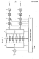
- FIG. 1 shows an exemplary embodiment of an arrangement for explaining the basic procedure for recording.
- a broadband satellite television signal is fed to the input (E).
- This signal is digitized in an analog-digital converter (1).
- the clock frequency required for digitization which is, for example, 20.25 MHz, is supplied by a control circuit (13), which is supplied with synchronizing pulses which either derived from the input signal or made available externally.
- the output signal of the analog-to-digital converter (1) is fed to a multiplexer (2) which divides the successive lines of the digitized broadband signal into memory units (M1, M2, ..., M6) of a memory (3).
- the signals are time-expanded in the storage units.
- Each of the storage units (M1, M2, ..., M6) can store the content of one line of the digitized broadband signal.
- the storage (3) is implemented in practice is left to the expert.
- the memory (3) in the form of a RAM, which could keep the number of lines low.
- the memory (3) can also be constructed in the form of shift registers.
- the multiplexer (2) is controlled, as is the control of the memory units (M1, M2, ..., M6) by the control circuit (13).
- the control of the memory units (M1, M2, ..., M6) means the selection of read-in clock, read-out clock, write-in time intervals and read-out time intervals.
- This control of the memory units (M1, M2, ... M6) is one of the main features of the present invention and is explained in more detail below in connection with FIG. 2.
- the signals read from the memory units (M1, M2, ..., M6) are divided into two channels 1 and 2 by means of a second multiplexer (4), which is also controlled by the control circuit (13).
- the two recording channels of Fig. 1 are constructed identically.
- Each channel contains a stage (5 or 6) for sync pulse input, a digital-to-analog converter (7 or 8), a frequency modulator (9 or 10) and a video head (11 or 12) for recording the signal on parallel Oblique traces of a magnetic tape.
- the stages (5 and 6) for sync pulse input and the digital-to-analog converter (7 and 8) are also controlled by the control circuit (13).
- the clock frequency for the digital-to-analog converters (7 and 8) is, for example, 10.25 MHz.
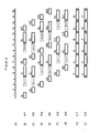
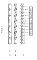
- FIG. 2A shows the successive lines 1 to 16 of the broadband input signal. These are cyclically fed to the memory units (M1, M2, ..., M6) in such a way that the 1st, 7th, 13th, ... line of the input signal into the first memory unit (M1), into the second memory unit (M2 ) the 2nd, 8th, 14th, ... line of the input signal, the 3rd, 9th, 15th, ...
- the line of the input signal is read into the third memory unit (M3), etc., These are write-in processes in Figures 2 B) to G) 1S, 2S, 3S, ..., 16S.
- the duration of one line is 64 usec, the registration clock is 20.25 MHz.
- the read processes from the memory units are designated 1L, 2L, 3L, ....
- the read cycle is slightly more than half the write cycle, for example 10.25 MHz.
- the duration of a line read from the memory is, for example, 126.44 ⁇ sec, which is slightly less than twice the duration of a line of the broadband input signal.
- the duration of each line could be doubled to 128 / us, thus halving the required recording bandwidth.
- a time span of 1.56 / us is obtained per line read from the memory according to the above exemplary embodiment. All of the time spans obtained within a time frame of 20 ms are used to generate two types of time gaps.
- the first time gaps are line-frequency, occur between the reading processes of two successive lines and amount to 1 ⁇ s, for example. These line-frequency gaps are hatched in FIG. 2.
- the second time gaps occur at the end of each 20 ms time frame. As will be explained later, there will be gaps in time Synchronous signals used. The head changeover takes place during the second time gap.
- the reading cycle was chosen to be greater than half the write-in cycle b , the time difference between the end of the reading process of a line and the beginning of the associated reading process becomes smaller as the number of lines increases. This is indicated in FIG. 2 by the dashed boxes or the arrows pointing to the left.
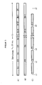
- FIG. 3 shows a sketch to explain the principle of the gap generation mentioned in connection with FIG. 2.
- FIG. 3a shows the individual lines of the broadband input signal in a channel in a time frame of 20 msec, which corresponds to the duration of a field.
- FIG. 3b shows individual lines of the input signal read out from the memory with a time expansion by a factor of 2.
- FIG. 3c shows the same lines of the input signal as FIG.
- first time gaps L1, L2, and LX
- LZ second time gap
- FIGS. 2h and 2i show how the control of the readout time intervals and the division of the individual time-expanded lines into the two recording channels shown in FIG. 1 take place.
- the reading processes from the memories always start simultaneously and consequently also end simultaneously.
- line 1 is read from memory (M1) at the same time as line 2 is read from memory (M2)
- line 3 is read from memory (M3) at the same time as line 4 is read from memory (M4 ), etc.
- the U and V components of the color-bearer signal are transmitted alternately in successive lines, i. H. for example, the U component is sent in lines 1, 3, 5, 7, 9, ..., and the V component in lines 2, 4, 6, 8, 10, ....
- the division of the individual time-expanded lines into the two recording channels is such that each recording channel is alternately assigned a line with the U component and a line with the V component of the chrominance signal. This division is only possible with the timing of the readout processes from the storage units described above.
- the signal shown in FIG. 2h is fed to the recording channel 1 and the signal shown in FIG. 2i to the recording channel 2 of the arrangement shown in FIG.
- each of these signals (5 and 6 respectively) are keyed to the dimensional Synchronsignaleintastung Synchronsi g in one stage.
- the signal obtained is analogized in a digital-to-analog converter (7 or 8), frequency-modulated (stage 9 or 10) and recorded by video heads (11 or 12) in oblique tracks on a magnetic tape.
- the recording is carried out in such a way that the synchronous signals of adjacent tracks that are keyed in between the image components are located side by side so that no synchronous signal crosstalk takes place from track to track during playback.
- the recording process was described for D2-MAC satellite television signals.
- other, similarly constructed broadband signals can also be recorded.
- purely digital or purely analog signal processing and recording is also possible, in which no A / D or D / A converter would be necessary.
- HDTV signals can in principle also be recorded with the described recording method. The division of successive lines would have to be carried out in such a way that two successive lines of the input signal are always fed to a memory unit of the memory (3). It is also possible to split the signal into more than two recording channels.
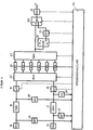
- Figure 4 shows an arrangement for explaining the basic procedure for playback.
- the signal reproduced by the video heads (14 or 15) is demodulated in a frequency demodulator (16 or 17).
- the demodulated signal reaches an analog-digital converter (18 or 19) and is digitized there.
- the digitized signal is distributed to the memory units (M1, M2, ..., M6) of a memory (21) by means of a multiplexer (20).
- the storage units (M1, M2, ..., M 6) are used for time compression of the reproduced signal.
- the signals read from the memory units are combined into a continuous broadband signal by means of a multiplexer (22).
- the continuous broadband signal reaches a digital-to-analog converter (24) on the one hand via a switch (S2), which is in switch position a, and is, on the other hand, via a switch (S1), which is also located in switch position a, is stored in a dropout memory (23), which has a memory capacity of two lines.
- the two switches (S1 and S2) are in the switch positions b, so that the output of the multiplexer (22) is separated from the subsequent circuit parts and the signals stored in the memory (23) are switched on via the switch (S2) the D / A converter (24) are passed on.
- the analog output signal of the D / A converter (24) reaches the output terminal (A) of the arrangement.
- a control circuit (25) which controls the operation of the digital-to-analog converter (18 and 19), the multiplexer (20), the memory unit (21), the multiplexer (22), the dropout memory (23), the switches ( S 1 and S 2) and the digital-to-analog converter (24) controls.
- the output signals from dropout detectors (26 and 27), which monitor the output signal of the video head (14 and 15) for dropouts, and the output signals from amplitude sieves (28 and 29) are applied to the control circuit (25) serve to separate the synchronous signals from the reproduced, frequency-demodulated signal of the respective channel.
- a time error compensation can thus be carried out in a simple manner by means of a suitable memory control.
- FIG. 5 shows an exemplary embodiment for explaining the distribution of the reproduced signals among the memory units (M1, M2, ..., M6), the writing and reading processes into or from the memory units, and the combination of the output signals of the memory units into a continuous signal .
- Figures 5a and 5b show the reproduced signals in the channels (K1 and K2).
- the hatched areas in turn represent the line-frequency gaps in which synchronizing pulses were used during the recording.
- the writing processes into the memory units (M1, M2, ..., M6) are denoted by 1S, 2S, ..., 12S in FIGS. 5c to 5h. Since the signals to be written into the memory units (M1, M2, ..., M6) are subject to time errors, the control circuit must be supplied with information describing the time errors. This is done by separating the synchronization signals inserted into the signal to be recorded from the reproduced signal of each channel. These synchronous signals, which are subject to time errors, are fed to the control circuit and are used by the control circuit in a generally known manner for time error correction.
- a time interval of - 1/4 line is available to compensate for the time error (see, for example, distance between the end of the writing process on the 7th line and the start of the reading process on the 7th line). If necessary, this time interval can be increased by using additional storage units.
- the exemplary embodiment shown in FIG. 6 explains how dropout compensation can take place in the case of a signal recorded according to the present invention.
- the signals shown in FIGS. 6a and 6b essentially correspond to the signals shown in FIGS. 5a and 5b, apart from the fact that the line-frequency gaps which are not necessary for understanding dropout compensation are omitted were.
- the 1st, 4th, 5th, 8th, 9th, 12th and 13th lines of the original signal and in playback channel 2 are the 2nd, 3rd, 6th, 7th, 100th, 11th . and 12th line of the original channel (in time-stretched form) included.
- lines in each channel alternate with the U and lines with the V component of the chrominance signal. This is beneficial for dropout compensation, as shown below:
- the next step is to use the dropout memory (23) to find the line with the correct color type information, ie in the present case the first line, and instead of disturbed 3rd line inserted in the signal.
- the following line to be reproduced ie the 4th line, is present undisturbed and is therefore fed directly to the D / A converter (24) on the one hand and on the other hand instead of the 2nd line, which also contains a V component of the color tone signal, in the dropout Storage (23) filed.
- This is followed by a reproduction of the undisturbed 5th line and a storage of this line instead of the previously stored 1st line, which also contains a U-grain component of the chrominance signal.
- the dropout compensation was carried out behind the multiplexer (22), that is to say with the signal which is no longer time-expanded. In principle, however, it is also conceivable to carry out the dropout compensation at a different point.
Landscapes
- Engineering & Computer Science (AREA)
- Multimedia (AREA)
- Signal Processing (AREA)
- Television Signal Processing For Recording (AREA)
Applications Claiming Priority (2)
| Application Number | Priority Date | Filing Date | Title |
|---|---|---|---|
| DE3613798 | 1986-04-24 | ||
| DE19863613798 DE3613798A1 (de) | 1986-04-24 | 1986-04-24 | Verfahren zur aufbereitung von fernsehsignalen |
Publications (3)
| Publication Number | Publication Date |
|---|---|
| EP0243739A2 true EP0243739A2 (fr) | 1987-11-04 |
| EP0243739A3 EP0243739A3 (en) | 1989-05-10 |
| EP0243739B1 EP0243739B1 (fr) | 1992-12-09 |
Family
ID=6299383
Family Applications (1)
| Application Number | Title | Priority Date | Filing Date |
|---|---|---|---|
| EP87105114A Expired - Lifetime EP0243739B1 (fr) | 1986-04-24 | 1987-04-07 | Procédé pour le traitement des signaux de télévision |
Country Status (2)
| Country | Link |
|---|---|
| EP (1) | EP0243739B1 (fr) |
| DE (2) | DE3613798A1 (fr) |
Cited By (3)
| Publication number | Priority date | Publication date | Assignee | Title |
|---|---|---|---|---|
| EP0262362A3 (en) * | 1986-08-30 | 1989-05-10 | Grundig E.M.V. Elektro-Mechanische Versuchsanstalt Max Grundig Holland. Stiftung & Co. Kg. | Method for recording and reproducing data packets transmitted with a television signal |
| FR2636801A1 (fr) * | 1988-09-21 | 1990-03-23 | France Etat | Procede d'enregistrement sur bande magnetique et de lecture de signaux d2-mac/paquet |
| FR2651949A1 (fr) * | 1989-09-13 | 1991-03-15 | France Etat | Procede d'enregistrement et de lecture de signaux de television a haute definition. |
Families Citing this family (2)
| Publication number | Priority date | Publication date | Assignee | Title |
|---|---|---|---|---|
| DE3630179A1 (de) * | 1986-09-04 | 1988-03-10 | Grundig Emv | Verfahren und einrichtung zur dropoutkompensation bei der wiedergabe magnetisch aufgezeichneter signale |
| DE3843821A1 (de) * | 1988-12-24 | 1990-06-28 | Broadcast Television Syst | Verfahren zur aufzeichnung von nach einem mac/paket-fernsehuebertragungsstandard codierten signalen |
Family Cites Families (4)
| Publication number | Priority date | Publication date | Assignee | Title |
|---|---|---|---|---|
| US4063284A (en) * | 1974-12-25 | 1977-12-13 | Sony Corporation | Time base corrector |
| DE2901034C3 (de) * | 1979-01-12 | 1984-08-09 | Grundig E.M.V. Elektro-Mechanische Versuchsanstalt Max Grundig & Co KG, 8510 Fürth | Verfahren und Schaltungsanordnung zur Komprimierung und Dekomprimierung von Analogsignalen in digitaler Form |
| US4467368A (en) * | 1981-08-12 | 1984-08-21 | Robert Bosch Gmbh | Method and means for recording and playback of color television signals |
| DE3381927D1 (de) * | 1982-12-02 | 1990-11-08 | Indep Broadcasting Authority | Geraet zur synchronisationssignalableitung fuer komponenten-fernsehvideosignalempfang. |
-
1986
- 1986-04-24 DE DE19863613798 patent/DE3613798A1/de not_active Withdrawn
-
1987
- 1987-04-07 EP EP87105114A patent/EP0243739B1/fr not_active Expired - Lifetime
- 1987-04-07 DE DE8787105114T patent/DE3782964D1/de not_active Expired - Lifetime
Cited By (6)
| Publication number | Priority date | Publication date | Assignee | Title |
|---|---|---|---|---|
| EP0262362A3 (en) * | 1986-08-30 | 1989-05-10 | Grundig E.M.V. Elektro-Mechanische Versuchsanstalt Max Grundig Holland. Stiftung & Co. Kg. | Method for recording and reproducing data packets transmitted with a television signal |
| US4868681A (en) * | 1986-08-30 | 1989-09-19 | U.S. Philips Corporation | Method and arrangement for recording and reproducing a data packet transmitted in a television signal |
| FR2636801A1 (fr) * | 1988-09-21 | 1990-03-23 | France Etat | Procede d'enregistrement sur bande magnetique et de lecture de signaux d2-mac/paquet |
| EP0360719A1 (fr) * | 1988-09-21 | 1990-03-28 | ETAT FRANCAIS représenté par le Ministre des PTT (Centre National d'Etudes des Télécommunications) | Procédé d'enregistrement sur bande magnétique et de lecture de signaux D2-MAC/PAQUET et dispositifs correspondants |
| FR2651949A1 (fr) * | 1989-09-13 | 1991-03-15 | France Etat | Procede d'enregistrement et de lecture de signaux de television a haute definition. |
| EP0418180A1 (fr) * | 1989-09-13 | 1991-03-20 | ETAT FRANCAIS représenté par le Ministre des P.T.T. (Centre National d'Etudes des Télécommunications-CNET) | Procédé d'enregistrement et de lecture de signaux de télévision à haute définition |
Also Published As
| Publication number | Publication date |
|---|---|
| DE3782964D1 (de) | 1993-01-21 |
| EP0243739A3 (en) | 1989-05-10 |
| EP0243739B1 (fr) | 1992-12-09 |
| DE3613798A1 (de) | 1987-10-29 |
Similar Documents
| Publication | Publication Date | Title |
|---|---|---|
| DE3885815T3 (de) | Digital-Signal-Übertragungseinrichtung. | |
| DE2629706C3 (de) | Verfahren zur Übertragung und/oder Aufzeichnung von Farbfernsehsignalen | |
| DE3787184T2 (de) | Videosignalaufzeichnungsmethode und Vorrichtung zur Teilbildaufnahme. | |
| DE69329739T2 (de) | Vorrichtung zur digitalen Aufzeichnung und/oder Wiedergabe eines Videosignals | |
| DE3115902C2 (fr) | ||
| EP0072507B1 (fr) | Procédé et arrangement de circuit pour l'enregistrement et/ou la reproduction de signaux à large bande | |
| DE3038594A1 (de) | Verfahren zum aufzeichnen eines farb-videosignals in einer vielzahl von parallelen, schraeg auf einem magnetband verlaufenden spuren | |
| DE3045541C2 (fr) | ||
| DE2901034B2 (de) | Verfahren und Schaltungsanordnung zur Komprimierung und Dekomprimierung von Analogsignalen in digitaler Form | |
| DE3542102A1 (de) | Fernsehgeraet mit fortlaufender abtastung | |
| EP0262362B1 (fr) | Procédé d'enregistrement et de reproduction de paquets de données transmis avec un signal de télévision | |
| DE3932271C2 (fr) | ||
| EP0318760A2 (fr) | Récepteur de télévision avec un dispositif de suppression des perturbations de scintillement | |
| EP0243739B1 (fr) | Procédé pour le traitement des signaux de télévision | |
| DE3702333C2 (de) | Aufzeichnungssystem und Wiedergabegerät für ein digitales Fernsehsignal | |
| DE3520537A1 (de) | Digital-videomagnetbandrecorder | |
| DE3131853C2 (de) | Verfahren und Schaltungsanordnung zum Aufzeichnen und/oder Wiedergeben von breitbandigen Signalen | |
| DE3034716C2 (de) | Magnetband mit Schrägspuraufzeichnung zeitlich komprimierter Ton- und Bildinformationssignalteile sowie Aufnahme- und Wiedergabevorrichtung hierfür | |
| DE69225103T2 (de) | Verfahren und Vorrichtung zum Erzeugen eines Kopiersignals mit hoher Geschwindigkeit | |
| DE3780544T2 (de) | Verfahren zum aufzeichnen eines videosignals und das assoziierende aufzeichnungs-/wiedergabegeraet. | |
| DE69019606T2 (de) | Fernsehsystem zur digitalen Übertragung von Bildsignalen. | |
| DE3431261A1 (de) | Farbfernsehwiedergabegeraet | |
| DE2945615A1 (de) | Digitales bildverarbeitungssystem fuer bewegte szenen | |
| DE69321303T2 (de) | Begleitinformationenthaltender digitaler Videorecorder | |
| DE3227373C1 (de) | Verfahren zur Speicherung digitalisierter Signale sowie Schaltungsanordnung zur Durchführung des Verfahrens |
Legal Events
| Date | Code | Title | Description |
|---|---|---|---|
| PUAI | Public reference made under article 153(3) epc to a published international application that has entered the european phase |
Free format text: ORIGINAL CODE: 0009012 |
|
| AK | Designated contracting states |
Kind code of ref document: A2 Designated state(s): CH DE FR GB IT LI |
|
| PUAL | Search report despatched |
Free format text: ORIGINAL CODE: 0009013 |
|
| AK | Designated contracting states |
Kind code of ref document: A3 Designated state(s): CH DE FR GB IT LI |
|
| 17P | Request for examination filed |
Effective date: 19890531 |
|
| 17Q | First examination report despatched |
Effective date: 19910917 |
|
| GRAA | (expected) grant |
Free format text: ORIGINAL CODE: 0009210 |
|
| AK | Designated contracting states |
Kind code of ref document: B1 Designated state(s): CH DE FR GB IT LI |
|
| GBT | Gb: translation of ep patent filed (gb section 77(6)(a)/1977) |
Effective date: 19921207 |
|
| REF | Corresponds to: |
Ref document number: 3782964 Country of ref document: DE Date of ref document: 19930121 |
|
| ET | Fr: translation filed | ||
| ITF | It: translation for a ep patent filed | ||
| REG | Reference to a national code |
Ref country code: GB Ref legal event code: 746 Effective date: 19930426 |
|
| REG | Reference to a national code |
Ref country code: FR Ref legal event code: DL |
|
| PLBE | No opposition filed within time limit |
Free format text: ORIGINAL CODE: 0009261 |
|
| STAA | Information on the status of an ep patent application or granted ep patent |
Free format text: STATUS: NO OPPOSITION FILED WITHIN TIME LIMIT |
|
| ITPR | It: changes in ownership of a european patent |
Owner name: OFFERTA DI LICENZA AL PUBBLICO |
|
| 26N | No opposition filed | ||
| REG | Reference to a national code |
Ref country code: CH Ref legal event code: PFA Free format text: GRUNDIG E.M.V. ELEKTRO- MECHANISCHE VERSUCHSANSTALT MAX GRUNDIG GMBH & CO. KG |
|
| REG | Reference to a national code |
Ref country code: FR Ref legal event code: CD |
|
| REG | Reference to a national code |
Ref country code: CH Ref legal event code: PFA Free format text: GRUNDIG E.M.V. ELEKTRO- MECHANISCHE VERSUCHSANSTALT MAX GRUNDIG GMBH & CO. KG TRANSFER- GRUNDIG AG |
|
| REG | Reference to a national code |
Ref country code: FR Ref legal event code: TP |
|
| REG | Reference to a national code |
Ref country code: GB Ref legal event code: IF02 |
|
| REG | Reference to a national code |
Ref country code: CH Ref legal event code: PUE Owner name: GRUNDIG MULTIMEDIA B.V. Free format text: GRUNDIG AG#KURGARTENSTRASSE 37#D-90762 FUERTH (DE) -TRANSFER TO- GRUNDIG MULTIMEDIA B.V.#DE BOELELAAN 7 OFF. I 2 HG#1083HJ AMSTERDAM (NL) |
|
| REG | Reference to a national code |
Ref country code: GB Ref legal event code: 732E |
|
| REG | Reference to a national code |
Ref country code: FR Ref legal event code: TP |
|
| PGFP | Annual fee paid to national office [announced via postgrant information from national office to epo] |
Ref country code: GB Payment date: 20060410 Year of fee payment: 20 |
|
| PGFP | Annual fee paid to national office [announced via postgrant information from national office to epo] |
Ref country code: FR Payment date: 20060418 Year of fee payment: 20 |
|
| PGFP | Annual fee paid to national office [announced via postgrant information from national office to epo] |
Ref country code: CH Payment date: 20060421 Year of fee payment: 20 |
|
| PGFP | Annual fee paid to national office [announced via postgrant information from national office to epo] |
Ref country code: IT Payment date: 20060430 Year of fee payment: 20 |
|
| PGFP | Annual fee paid to national office [announced via postgrant information from national office to epo] |
Ref country code: DE Payment date: 20060508 Year of fee payment: 20 |
|
| REG | Reference to a national code |
Ref country code: CH Ref legal event code: PL |
|
| REG | Reference to a national code |
Ref country code: GB Ref legal event code: PE20 |
|
| PG25 | Lapsed in a contracting state [announced via postgrant information from national office to epo] |
Ref country code: GB Free format text: LAPSE BECAUSE OF EXPIRATION OF PROTECTION Effective date: 20070406 |