EP0243710A2 - Mit Kühlrippen versehener flexibler Wärmetauscher - Google Patents
Mit Kühlrippen versehener flexibler Wärmetauscher Download PDFInfo
- Publication number
- EP0243710A2 EP0243710A2 EP87104809A EP87104809A EP0243710A2 EP 0243710 A2 EP0243710 A2 EP 0243710A2 EP 87104809 A EP87104809 A EP 87104809A EP 87104809 A EP87104809 A EP 87104809A EP 0243710 A2 EP0243710 A2 EP 0243710A2
- Authority
- EP
- European Patent Office
- Prior art keywords
- sheet
- heat exchanger
- fins
- chips
- coolant
- Prior art date
- Legal status (The legal status is an assumption and is not a legal conclusion. Google has not performed a legal analysis and makes no representation as to the accuracy of the status listed.)
- Withdrawn
Links
Images


Classifications
-
- H10W40/43—
-
- F—MECHANICAL ENGINEERING; LIGHTING; HEATING; WEAPONS; BLASTING
- F28—HEAT EXCHANGE IN GENERAL
- F28F—DETAILS OF HEAT-EXCHANGE AND HEAT-TRANSFER APPARATUS, OF GENERAL APPLICATION
- F28F19/00—Preventing the formation of deposits or corrosion, e.g. by using filters or scrapers
- F28F19/02—Preventing the formation of deposits or corrosion, e.g. by using filters or scrapers by using coatings, e.g. vitreous or enamel coatings
- F28F19/06—Preventing the formation of deposits or corrosion, e.g. by using filters or scrapers by using coatings, e.g. vitreous or enamel coatings of metal
-
- F—MECHANICAL ENGINEERING; LIGHTING; HEATING; WEAPONS; BLASTING
- F28—HEAT EXCHANGE IN GENERAL
- F28F—DETAILS OF HEAT-EXCHANGE AND HEAT-TRANSFER APPARATUS, OF GENERAL APPLICATION
- F28F21/00—Constructions of heat-exchange apparatus characterised by the selection of particular materials
- F28F21/08—Constructions of heat-exchange apparatus characterised by the selection of particular materials of metal
- F28F21/081—Heat exchange elements made from metals or metal alloys
- F28F21/085—Heat exchange elements made from metals or metal alloys from copper or copper alloys
-
- F—MECHANICAL ENGINEERING; LIGHTING; HEATING; WEAPONS; BLASTING
- F28—HEAT EXCHANGE IN GENERAL
- F28F—DETAILS OF HEAT-EXCHANGE AND HEAT-TRANSFER APPARATUS, OF GENERAL APPLICATION
- F28F3/00—Plate-like or laminated elements; Assemblies of plate-like or laminated elements
- F28F3/02—Elements or assemblies thereof with means for increasing heat-transfer area, e.g. with fins, with recesses, with corrugations
- F28F3/04—Elements or assemblies thereof with means for increasing heat-transfer area, e.g. with fins, with recesses, with corrugations the means being integral with the element
- F28F3/048—Elements or assemblies thereof with means for increasing heat-transfer area, e.g. with fins, with recesses, with corrugations the means being integral with the element in the form of ribs integral with the element or local variations in thickness of the element, e.g. grooves, microchannels
-
- H10W40/774—
-
- F—MECHANICAL ENGINEERING; LIGHTING; HEATING; WEAPONS; BLASTING
- F28—HEAT EXCHANGE IN GENERAL
- F28F—DETAILS OF HEAT-EXCHANGE AND HEAT-TRANSFER APPARATUS, OF GENERAL APPLICATION
- F28F2255/00—Heat exchanger elements made of materials having special features or resulting from particular manufacturing processes
- F28F2255/02—Flexible elements
-
- F—MECHANICAL ENGINEERING; LIGHTING; HEATING; WEAPONS; BLASTING
- F28—HEAT EXCHANGE IN GENERAL
- F28F—DETAILS OF HEAT-EXCHANGE AND HEAT-TRANSFER APPARATUS, OF GENERAL APPLICATION
- F28F2255/00—Heat exchanger elements made of materials having special features or resulting from particular manufacturing processes
- F28F2255/14—Heat exchanger elements made of materials having special features or resulting from particular manufacturing processes molded
Definitions
- This invention relates to a heat exchanger for transference of heat from an array of electronic circuit chips and, more particularly, to a flexible sheet having cooling fins thereon to be placed directly on the array of chips.
- Arrays of electronic circuit chips are interconnected to provide vast electronic circuits. Such circuits may be employed in computers and other electronic systems utilizing very large numbers of electronic circuit components.
- the many transistors and other circuit components present within a circuit chip dissipate heat in response to activation with current from an electric power supply. In order for the circuits to function properly, the heat must be removed to maintain proper operating temperature for the circuits.
- cooling which has been proposed is the use of a metal plate held against circuit chips by springs, as is disclosed by Cutchaw, U.S. patent 4,381,032.
- Another form of heat exchanger for cooling electronic circuits provides for passages within which liquid coolant is circulated, the coolant contacting a flexible wall which presses against the circuitry to be cooled, as shown in Wilson et al, U.S. patent 4,072,188.
- Another form of heat exchanger employs coated metallic dendrites which are held by springs against a circuit chip, as disclosed in Babuka et al, U.S. patent 4,254,431.
- Yet another form of heat exchanger employs a pillow structure formed of film and filled with a thermal liquid material for extracting heat from an electric circuit, as is disclosed in Spaight, U.S. patent 4,092,697. Also a malleable dimpled wafer is deformed by pressure between a heat source such as an electronic circuit and a heat sink, as is disclosed in Rhoades et al, U.S. patent 4,151,547.
- a theoretical discussion of cooling considerations is presented in an article in the IEEE Electron Device Letters, "High Performance Heat Sinking For VLSI" by D.B. Tuckerman and R.F.W. Pease, Vol. EDL-2, No. 5, May 1981, pp. 126-129.
- heat exchanger which, in accordance with the invention as claimed, is formed as a flexible sheet of thermally conductive material, and is provided with a set of fins of thermally conductive material upstanding upon the flexible sheet.
- the sheet is large enough to encompass an array of circuit chips disposed on a common substrate and can completely blanket the array of chips.
- the sheet can be attached to the substrate, by use of suitable adhesives, so as to hermetically seal the chips against any contamination by a fluid coolant.
- the sheet may be provided with corrugations at locations between the sites of the chips so as to provide for greater flexibility and the capacity for fully aligning each portion of the sheet with the corresponding surface of a chip.
- the fins are arranged in the direction of coolant flow, thereby to transfer more effectively the heat of the chip to the coolant.
- the fins are arranged in a staggered array to promote the flow of coolant and contact between the coolant and the fins.
- the thickness of the fins is approximately equal to the spacing between fins which, in turn, is approximately equal to the thickness of the sheet, typically 0.05 mm.
- the material used in the construction of the heat exchanger is dependent on the nature of the coolant.
- the sheet and fins of the heat exchanger may be constructed of copper which provides for good thermal conductivity and, in addition, is flexible at sheet thicknesses in the range of 0.012-0.125 mm.
- the copper of the fins is coated with a metal such as nickel which prevents corrosion of the heat exchanger by the water. Chromium or its alloys may also be used to coat the heat exchanger.
- a thermally conducting grease may be used as a thermally conducting grease.
- a spring loaded plate may be applied against the tops of the fins to urge the heat exchanger structure against the array of chips, thereby to promote good thermal conductivity between the heat exchanger and the chips.
- Important features of the invention are the establishment of fine groove forced convection cooling, a flexible hermetically sealing sheet, and a fabrication of the exchanger by photolithographic techniques as are employed in the production of printed circuits.
- the thickness of the fins and width of the grooves are both equal approximately to 0.05 mm, such dimensions being well suited for the transference of heat from the fins to a liquid coolant such as water.
- the chips may be mounted to a substrate by means of fragile connections in the form of solder balls, which balls may be broken by excessive stress upon a chip.
- the flexible sheet in addition to protecting the circuit chips from contaminants by hermetic sealing, also relieves the foregoing stresses between chips so as to protect the connections between the chips and the substrate.
- the convenience of manufacture of the heat exchanger by photolithographic technology is attainable because of the small fin and groove dimensions, noted above, which dimensions are suitable for masking and additive plating to form the cooling structure of the fins and grooves.
- an electronic system 20 is formed as an array of circuit chips 22 disposed on a common substrate 24. Electrical connections between the chips 22 are accomplished by well-known conductors (not shown) within the substrate 24 and a set of soft metal solder ball connections 26 (known as C4's) located between terminals of the chips 22 and the conductors of the substrate 24. Heat generated within the chips 22 by electric currents flowing within the circuits of the chips 22 is removed by means of a fluid coolant provided by a chiller 28 and conveyed therefrom to the chips 22 by a supply conduit 30 and a return conduit 32. A duct 34, partially shown in FIGS. 1 and 3, guides the coolant past the chips 22 between the conduits 30 and 32. The chips 22 of FIG.
- 1 may represent only a portion of the system 20, additional chips (not shown on the FIG.) also being provided with supply and return conduits (not shown) which conduits in combination with the conduits 30 and 32 constitute a manifold for conducting coolant between the chiller 28 and the electronic system 20.
- the cooling of the chips 22 is accomplished more efficiently by the use of a heat exchanger 36 comprising a flexible sheet 38 of thermally conductive material with fins 40 of thermally conductive material extending away from the sheet 38.
- the sheet 38 is shown covering the chips 22, with a part of the sheet 38 being cut away to show partially two of the chips 22. Due to the flexibility of the sheet 38, the heat exchanger 36 covers the chips 22 and the substrate 24 in the manner of a blanket. The flexibility of the sheet 38 provides for the relief of stress exerted on the chips 22, otherwise due to the cooling system.
- solder ball connections 26 have a diameter of only 0.125 mm, and are susceptible to fracture. The foregoing stresses cannot be transmitted via the sheet 38 to another chip because of the flexing action of the sheet 38. This protects the connections 26.
- a suitable thermally conductive material for construction of the heat exchanger 36 is a flexible metal, such as copper.
- the configuration of the fins 40 upstanding from the metal sheet may by referred to as a "metal velvet" because one side of the sheet has a fine fin structure while the opposite side of the sheet is smooth.
- the heat exchanger 36 may have relatively large fins for air cooling, the "velvet" effect of the smaller fins for water cooling is advantageous because the smaller fin size, fin thickness and groove width of 0.05 mm, enhances the transfer of heat from the fins to water.
- the fins 40 are oriented in a regular array to form grooves 42 between the fins 40 which are aligned along the direction of coolant flow so as to guide the coolant among the fins 40.
- the fins 40 are located on the sheet 38 only at those locations corresponding to sites of the chips 22.
- the flexibility of the sheet 38 permits the heat exchanger 36 to conform to the individual orientations of the surfaces of the chips 22 for enhanced conduction of heat from each chip 22 to the coolant.
- a pressure plate 46 may be applied to the top ends of the fins 40 and pressed against the heat exchanger 36 by a spring 48 secured to the ducts 34 of the cooling manifold.
- the pressure exerted by the spring 48 is sufficiently small so as to preclude any bending of the fins 40, but is sufficiently large to promote thermal contact between the sheet 38 and the top surface of a chip 22, such as the middle chip depicted in FIG. 3 with the pressure plate 46.
- the fins 40 may be arranged in rows and columns, as shown in FIG. 2, or alternatively, may be located in a staggered array as shown diagrammatically in FIG. 4. In both cases, the orientation of the fins 40 follows the lines of coolant flow so as to provide for good conduction of heat from the fins 40 into the coolant.
- the spacing between the fins 40 is approximately equal to the thickness of an individual fin, thereby to minimize the build up of any thermal boundary layer within the coolant, as the coolant flows past the fins 40.
- the material of the heat exchanger may be coated with a coating 50 to protect the material 52 from any corrosive effects of the coolant.
- the coating 50 is not required with non-corrosive coolants.
- the coolant is air
- a suitable material for the heat exchanger 36 is copper. Because air is not corrosive, an anodized coating or even no coating may be sufficient.
- the copper should be coated with a coating 50 of nickel to prevent corrosion of the copper by the water.
- a portion of one of the fins 40 is partially cut away to show the coating 50 upon a base material 52 of copper.
- the base material 52 and the nickel coating 50 may be seen in the sectioned portion of the sheet 28.
- Another suitable material for construction of the heat exchanger 36 is stainless steel. While the stainless steel is not as good a thermal conductor as copper, it is resistant to corrosive coolants, and may be used without a coating.
- a low-temperature soft metal alloy solder between the chip 22 and the sheet 38 for best heat conductivity.
- a thin layer of other thermally conductive material may be placed between the chip 22 and the sheet 38, suitable material being a well-known grease or oil with zinc oxide.
- suitable materials include a soft silicone elastomer which may include thermally conductive particles such as silicon carbide.
- the spacing and sizes of the fins 40 are selected in accordance with the particular coolant to be employed.
- the fins 40 can extend away from the sheet 38 a distance of almost 25 mm, and may be spaced apart with a spacing of 3 mm.
- the fins may be spaced apart by 0.05 mm, and may have a thickness of 0.05 mm, the individual fin extending along the direction of coolant flow for a distance of 0.3 mm.
- a particular advantage in the use of the heat exchanger 36 of the invention is the fact that it can be placed on a relatively large array of chips 22, for example an array of 100 chips, without the requirement for any precise dimensional alignment, due to the flexibility of the heat exchanger 36.
- An additional feature is attained by adhesively securing the perimeter of the sheet 38 to the substrate 24, thereby to hermetically seal all of the chips 22 from the coolant.
- the thickness of the metal sheet 38 is selected in accordance with the specific material employed in the construction of the heat exchanger 36, a thickness in the range of 0.02 - 0.25 mm being suitable for copper.
- a thickness on the order of 0.05 - 0.08 mm of copper provides good thermal conduction in the fins 40.
- the Cu base preferably should be absent, and then the nickel overcoat alone should form a flexible sheet. In the positioning of the fins 40 at the site of a chip 22, typically fifty of the fins are located at the site of one chip 22.
- the chips 22 may be placed on a substrate in the form of a ceramic tile having a size of typically 10 cm by 10 cm.
- the sheet 38 is made sufficiently large to cover the entire tile, thus greatly facilitating the manufacturing process for construction of the system 20.
- both the substrate 24 and the chips 22 are rigid, it is advantageous to employ a heat exchanger which is so constructed as to avoid introduction of stresses and strains between the chips and the substrate so as to avoid cracking the solder ball connections 26.
- the heat exchanger 36 of the invention does not apply stresses by virtue of its flexible construction.
- the heat exchanger is most readily fabricated in a manner analogous to the processes used to fabricate printed circuits. Start with a smooth aluminum mandrel, shaped for the corrugations. Apply a mask, and selectively plate copper fins at each chip location. Overcoat these fins and mandrel by electroless deposition of a thin layer of amorphous nickel. Etch away the mandrel with an alkali solution. Thus over each chip are Cu fins covered with a layer of nickel. Between the chips is a thin layer of nickel, shaped with corrugations.
- the heat exchanger 36 is readily manufactured by the processes portrayed in FIGS. 5 and 6.
- a mold 54 is provided with voids 56 having the shape of a fin 40.
- the heat exchanger 36 is cast by pouring molten metal 58 from a ladle 60 into the mold 54. Thereafter, the mold is cooled to solidify the metal. Upon removal of the mold from the metal, there is attained the heat exchanger 36 with integrally formed fins 40 upon the sheet 38. Only a portion of the mold 54 is shown to facilitate the description. However, it is to be understood that a larger mold would include voids for forming the corrugations 44 in a large sheet of the heat exchanger. Thereby, the entire heat exchanger 36 can be formed in a single manufacturing process.
- the manufacturing process begins with the preparation of a sheet 62 of thermally conducting material such as copper.
- a mask 64 is developed upon the upper surface of the sheet 62, the mask 64 being provided with voids 66 having the shape of a fin 40.
- metal such as copper
- a source 68 is provided by a source 68 and deposited by chemical vapor deposition to build up fins 40 within the voids 66 of the mask 64.
- the mask 64 is removed, by conventional means, and a further source 70 is employed for depositing a coating, such as a nickel coating upon the completed assembly to provide the coated sheet 38 and fins 40 of the heat exchanger 36.
- Corrugations may be placed within the sheet 38 by a mechanical process such as swagging employing a preformed anvil, or similar mechanical form (not shown) to form the corrugations.
- a heat exchanger 36 can be fabricated in a sufficiently large size to cover a relatively large array of the chips 22.
- FIGS. 7 - 8 show an electronic system 72, similar to the system 20 (FIG. 1) formed as an array of circuit chips 74 disposed on a common substrate 76. Cooling of the chips 74 is accomplished by a heat exchanger 78 constructed in accordance with a further embodiment of the invention wherein separate sets of cooling fins 80 are connected to a flexible sheet 82 with the aid of semi-rigid pads 84 formed of a thermally conductive material such as copper.
- the fins 80 are formed of copper to provide good conduction of heat from the chips 74 to streams of cooling air, indicated by arrows.
- the sheet 82 is formed of an electrically insulating plastic material such as a polycarbonate marketed under the trademark name of "Kapton".
- the cooling air is conducted via a conduit 86 (FIG. 8) and guided via a plenum 88 to individual sets of the fins 80.
- Springs 90 (only one of which is shown in FIG. 8) are located between the respective sets of fins 80 and a wall 92 of the conduit 86 for pressing the pads 84 against the corresponding chips 74 to secure good thermal contact between the pads 84 and the chips 74.
- a layer 94 of a thermally conductive grease is disposed between each pad 84 and its corresponding chip 74 to attain still further thermal conductivity between the chips 74 and the pads 84.
- This embodiment of the invention provides for a rigid connection between the fins 80 and the pads 84, the rigid connection allowing for a much greater height to the fins 80 than is practicable for the fins 40 of FIG. 3.
- the extra height is particularly advantageous for the case of air cooling wherein a larger contact region, between fin and coolant, should be employed than in the case of liquid coolant.
- the heat exchanger 78 may be constructed, by way of example, by forming a laminate of copper sheet and the plastic sheet 82, positioning the fins 80 in contact with the copper sheet via apertures 96 (FIG. 8) in the sheet 82, and securing the fins 80 to the copper sheet as by low temperature soldering, 150 degrees Celsius.
- the soldering is done at a temperature which is sufficiently low so as not to damage the plastic material of the sheet 82. Thereafter, the copper sheet is etched to form troughs 98 which define the individual pads 84 and electrically insulate the pads 84 from each other.
- an array of assemblies of pads 84 with their respective set of fins 80 may be formed by conventional means, and then the set of fins 80 are passed through the apertures 96 in the plastic sheet 82. Thereafter, the pads 84 are bonded to the sheet 82 to form the heat exchanger 78.
- the flexibility of the sheet 82 allows each of the pads 84 to lie upon the surface of the corresponding chip 74 independently of chip height and orientation relative to the substrate 76. Also, the sheet 82 pneumatically seals the chips 74 in the same fashion as has been described above with respect to the embodiment of FIG. 1.
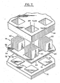
- FIG. 9 shows a simplified view of an electronic system 100 comprising a set of electronic circuit chips 102 disposed on a common substrate 104 containing electrical conductors (not shown) for making electrical connections among the circuits of the chips 102.
- a set of C4 solder balls serve as connections 106 between terminals of the chip circuits and the conductors of the substrate 104.
- the system 100 includes a heat exchanger 108 constructed in accordance with a further embodiment of the invention and comprising a set of fin assemblies 110 each of which is formed of a set of fins 112 and a base 114 which supports the fins 112.
- Each of the fin assemblied 110 rests upon a corresponding one of the chips 102, and is thermally coupled thereto by means of a layer 116 of thermally conductive grease or soft solder or other highly thermally conducting interfaces.
- a flexible sheet 118 of thermally conductive material, such as amorphous nickel, is deposited upon the fin array assemblies 100 so as to form intimate contact therewith.
- Each fin assembly 110 is formed of a thermally conductive material such as copper or silicon.
- an electronic system 120 which, like the system 100 of FIG. 9, also comprises a substrate 104 with a set of circuit chips 102 connected thereto by connections 106.
- the system 120 includes a heat exchanger 122 which is an alternative embodiment of the heat exchanger 108 of FIG. 9.
- the heat exchanger 122 comprises a set of fin assemblies 124 each of which is formed of a set of fins 126 and a base 128 which supports the fins 126.
- Each of the fin assemblies 124 is positioned above a corresponding one of the chips 102, and rests upon a flexible sheet 130 disposed between the fin assemblies 124 and the chips 102.
- each fin assembly 124 is thermally coupled through the sheet 130 to the corresponding chip 102 by means of a layer 116 of thermally conductive grease.
- the sheet 130 is formed of thermally conductive material, such as amorphous nickel.
- Each fin assembly 124 is formed of a thermally conductive material such as copper or silicon.
- the fins 110 and 124 are constructed first, by selective copper plating, and then the amorphous nickel is deposited on the fins to form the exchanger 108, or upon an array of the assemblies 124 to form the exchanger 122.
- the deposition of the amorphous nickel is accomplished with the aid of a mandrel which holds the fins 110 or 124 in their respective arrays.
- the nickel is deposited upon the fin assemblies and upon the mandrel by electroless deposition, after which the fin assemblies are removed from the mandrel to complete formation of the heat exchanger 108 or 122.
- the sheets of the heat exchangers hermetically seal the chips 102.
- the bases 114 and 128 rigidly support their respective fins 112 and 126 so as to accommodate short or tall fins as may be required for a particular coolant such as air or water.
- the flexibility of the respective sheets 118 or 130 permit the fin assemblies 110 or 124, respectively, to be individually positioned in accordance with the height and orientation of the respective chips 102 relative to the substrate 104.
- a coolant is to be delivered by a conduit (not shown) such as that disclosed previously in FIGS. 1 or 8.
- the assembly 132 comprises a circuit chip 134 supported by a substrate 136, and cooled by a heat exchanger 138 having a set of fins 140 supported on a base 142.
- a frame 144 comprises circumferential sidewalls 146 positioned for encircling the substrate 136, and further comprises a flexible sheet 148 supported by the sidewalls 146 and bonded to flanges 150 which are directed inwardly from the tops of the sidewalls 146.
- the base 142 is bonded to the sheet 148 and, upon a joining of the frame 144 to the substrate 136, is sufficiently flexible to extend downward to the top surface of the chip 134 for alignment of the base 142 with the chip 134.
- the sheet 148 is fabricated of a thermally conductive material such as copper, and contacts both the chip 134 and the base 142 to provide for the conduction of heat from the chip 134 to the heat exchanger 138.
- the fins 140 may be formed as a square array of pins wherein each pin has a diameter of 2.4 mm and a height of 3 cm.
- the base 142 is approximately 2.3 mm thick and has a central stud portion 164 which extends downward an additional 2.3 mm.
- the base 142 and the fins 140 upstanding therefrom are formed as an integral assembly of a thermally conductive material such as copper.
- the construction begins, as shown in FIG. 11, by positioning the heat exchanger 138 with the frame 144 and the sheet 148 attached thereto above the substrate 136 and the chip 134 thereon.
- a layer 152 of thermally enhanced grease is applied to the top surface of the chip 134, and then the frame 144 is lowered to loosely contact the peripheral portions of the substrate 136, as shown in FIG. 12.
- the substrate 136 sets within shoulders 154 formed within the sidewalls 146.
- the heat exchanger 138 is lowered still further, by flexing of the sheet 148, and squeezing the grease to contact the chip 134.
- the layer 152 of grease between the sheet 148 and the chip 134 provides for thermal conduction therebetween upon a pressing of the base 142 against the sheet 148 and the chip 134.
- the base 142 is bonded at 156 to the tops of the sidewalls 146 to rigidly secure the heat exchanger 138 in position relative to the chip 134.
- Bottom skirt portions of the sidewalls 146 may also be bonded at 158 to the substrate 136 to hermetically seal the chip 134.
- circuit module assembly 132 may include plural chips, each of which is connected by C4 solder-ball connections 160 to conductors (not shown) within the substrate 136, thereby to function in the manner of the system 20 of FIG. 1.
- Pins 162 extending downward from the substrate 136 permit connection with other modules (not shown) of the circuit assembly.
- the heat exchanger should be divided into plural segments to closely contact each of a plurality of chips.
Landscapes
- Engineering & Computer Science (AREA)
- Physics & Mathematics (AREA)
- Thermal Sciences (AREA)
- Mechanical Engineering (AREA)
- General Engineering & Computer Science (AREA)
- Cooling Or The Like Of Semiconductors Or Solid State Devices (AREA)
- Cooling Or The Like Of Electrical Apparatus (AREA)
Applications Claiming Priority (2)
| Application Number | Priority Date | Filing Date | Title |
|---|---|---|---|
| US06/858,318 US4730666A (en) | 1986-04-30 | 1986-04-30 | Flexible finned heat exchanger |
| US858318 | 1986-04-30 |
Publications (2)
| Publication Number | Publication Date |
|---|---|
| EP0243710A2 true EP0243710A2 (de) | 1987-11-04 |
| EP0243710A3 EP0243710A3 (de) | 1989-11-29 |
Family
ID=25328017
Family Applications (1)
| Application Number | Title | Priority Date | Filing Date |
|---|---|---|---|
| EP87104809A Withdrawn EP0243710A3 (de) | 1986-04-30 | 1987-04-01 | Mit Kühlrippen versehener flexibler Wärmetauscher |
Country Status (3)
| Country | Link |
|---|---|
| US (1) | US4730666A (de) |
| EP (1) | EP0243710A3 (de) |
| JP (1) | JPH0779142B2 (de) |
Cited By (10)
| Publication number | Priority date | Publication date | Assignee | Title |
|---|---|---|---|---|
| WO1990005381A1 (en) * | 1988-10-31 | 1990-05-17 | Unisys Corporation | Liquid cooled multi-chip integrated circuit module |
| DE4312057A1 (de) * | 1993-04-13 | 1993-10-14 | Siegmund Maettig | Vorrichtung zum Kühlen hochintegrierter Multi-Chip-Moduls für Datenverarbeitungsanlagen mit hoher Rechnerleistung |
| DE4210834A1 (de) * | 1992-04-01 | 1993-10-14 | Siemens Nixdorf Inf Syst | Einrichtung zum Kühlen von zu Flachbaugruppen zusammengefaßten gehäuselosen filmmontierten integrierten Bausteinen |
| GB2271468A (en) * | 1992-10-06 | 1994-04-13 | Hewlett Packard Co | Mechanically floating multi-chip substrate |
| US5323292A (en) * | 1992-10-06 | 1994-06-21 | Hewlett-Packard Company | Integrated multi-chip module having a conformal chip/heat exchanger interface |
| US5353867A (en) * | 1992-03-31 | 1994-10-11 | Akzo Nobel Nv | Heat exchanger, a method of manufacturing same, and applications |
| US5396403A (en) * | 1993-07-06 | 1995-03-07 | Hewlett-Packard Company | Heat sink assembly with thermally-conductive plate for a plurality of integrated circuits on a substrate |
| US5430611A (en) * | 1993-07-06 | 1995-07-04 | Hewlett-Packard Company | Spring-biased heat sink assembly for a plurality of integrated circuits on a substrate |
| WO2005096377A1 (en) * | 2004-03-31 | 2005-10-13 | Hydrocool Pty Limited | A heat exchanger |
| AU2005228057B2 (en) * | 2004-03-31 | 2010-02-18 | Hydrocool Pty Limited | A heat exchanger |
Families Citing this family (29)
| Publication number | Priority date | Publication date | Assignee | Title |
|---|---|---|---|---|
| US4964458A (en) * | 1986-04-30 | 1990-10-23 | International Business Machines Corporation | Flexible finned heat exchanger |
| JPS63134268U (de) * | 1987-02-13 | 1988-09-02 | ||
| US4960634A (en) * | 1990-03-14 | 1990-10-02 | International Business Machines Corporation | Epoxy composition of increased thermal conductivity and use thereof |
| US5014117A (en) * | 1990-03-30 | 1991-05-07 | International Business Machines Corporation | High conduction flexible fin cooling module |
| US5265670A (en) * | 1990-04-27 | 1993-11-30 | International Business Machines Corporation | Convection transfer system |
| JPH07114250B2 (ja) * | 1990-04-27 | 1995-12-06 | インターナショナル・ビジネス・マシーンズ・コーポレイション | 熱伝達システム |
| US5291371A (en) * | 1990-04-27 | 1994-03-01 | International Business Machines Corporation | Thermal joint |
| US5201866A (en) * | 1992-02-03 | 1993-04-13 | International Business Machines Corporation | Structure for dissipation of heat having slidably engaged fins for conformal disposition against a heat generating surface |
| US5265321A (en) * | 1992-09-22 | 1993-11-30 | Microelectronics And Computer Technology Corporation | Integrated circuit structure with heat exchanger elements secured thereto and method of making |
| US5309321A (en) * | 1992-09-22 | 1994-05-03 | Microelectronics And Computer Technology Corporation | Thermally conductive screen mesh for encapsulated integrated circuit packages |
| US5344795A (en) * | 1992-09-22 | 1994-09-06 | Microelectronics And Computer Technology Corporation | Method for encapsulating an integrated circuit using a removable heatsink support block |
| JP3007497B2 (ja) * | 1992-11-11 | 2000-02-07 | 三菱電機株式会社 | 半導体集積回路装置、その製造方法、及びその実装方法 |
| JPH06213588A (ja) * | 1992-12-04 | 1994-08-02 | American Teleph & Telegr Co <Att> | 回路パックとそのヒートシンクの構造を最適化する方法 |
| US5653280A (en) * | 1995-11-06 | 1997-08-05 | Ncr Corporation | Heat sink assembly and method of affixing the same to electronic devices |
| US20030066632A1 (en) * | 2001-10-09 | 2003-04-10 | Charles J. Bishop | Corrosion-resistant heat exchanger |
| JP4562770B2 (ja) | 2005-04-15 | 2010-10-13 | 富士通株式会社 | ヒートシンク、回路基板、電子機器 |
| JP4928749B2 (ja) * | 2005-06-30 | 2012-05-09 | 株式会社東芝 | 冷却装置 |
| US7673389B2 (en) * | 2005-07-19 | 2010-03-09 | International Business Machines Corporation | Cold plate apparatus and method of fabrication thereof with a controlled heat transfer characteristic between a metallurgically bonded tube and heat sink for facilitating cooling of an electronics component |
| US8289710B2 (en) | 2006-02-16 | 2012-10-16 | Liebert Corporation | Liquid cooling systems for server applications |
| US7849914B2 (en) * | 2006-05-02 | 2010-12-14 | Clockspeed, Inc. | Cooling apparatus for microelectronic devices |
| JP4675283B2 (ja) * | 2006-06-14 | 2011-04-20 | トヨタ自動車株式会社 | ヒートシンクおよび冷却器 |
| US8176972B2 (en) * | 2006-08-31 | 2012-05-15 | International Business Machines Corporation | Compliant vapor chamber chip packaging |
| US8120169B2 (en) * | 2008-02-26 | 2012-02-21 | Fairchild Semiconductor Corporation | Thermally enhanced molded leadless package |
| TW201028639A (en) * | 2009-01-20 | 2010-08-01 | Wistron Corp | Heat fin, heat sink and the method for increasing heat dissipation of the heat fin |
| US20110253347A1 (en) * | 2010-04-19 | 2011-10-20 | Steve Harrington | Vacuum Pumped Liquid Cooling System for Computers |
| US8820351B1 (en) | 2013-06-25 | 2014-09-02 | Chilldyne, Inc. | No drip hot swap connector and method of use |
| US20160025426A1 (en) * | 2014-07-22 | 2016-01-28 | Hamilton Sundstrand Space Systems International, Inc. | Heat transfer plate |
| US10175005B2 (en) * | 2015-03-30 | 2019-01-08 | Infinera Corporation | Low-cost nano-heat pipe |
| US11348856B2 (en) * | 2019-12-20 | 2022-05-31 | Micron Technology, Inc. | Thermal cooling element for memory devices of a memory sub-system |
Family Cites Families (18)
| Publication number | Priority date | Publication date | Assignee | Title |
|---|---|---|---|---|
| CH342661A (de) * | 1956-08-11 | 1959-11-30 | Bbc Brown Boveri & Cie | Kühler für die Kühlung eines Halbleiterelementes |
| US3877062A (en) * | 1966-09-14 | 1975-04-08 | Siemens Ag | Method for producing metal structures upon semiconductor surfaces |
| US3864728A (en) * | 1970-11-20 | 1975-02-04 | Siemens Ag | Semiconductor components having bimetallic lead connected thereto |
| US3860949A (en) * | 1973-09-12 | 1975-01-14 | Rca Corp | Semiconductor mounting devices made by soldering flat surfaces to each other |
| US4072188A (en) * | 1975-07-02 | 1978-02-07 | Honeywell Information Systems Inc. | Fluid cooling systems for electronic systems |
| JPS5266376A (en) * | 1975-11-29 | 1977-06-01 | Hitachi Ltd | Device and manufacture of resin body type semiconductor |
| US4069498A (en) * | 1976-11-03 | 1978-01-17 | International Business Machines Corporation | Studded heat exchanger for integrated circuit package |
| US4092697A (en) * | 1976-12-06 | 1978-05-30 | International Business Machines Corporation | Heat transfer mechanism for integrated circuit package |
| GB1598174A (en) * | 1977-05-31 | 1981-09-16 | Ibm | Cooling electrical apparatus |
| US4151547A (en) * | 1977-09-07 | 1979-04-24 | General Electric Company | Arrangement for heat transfer between a heat source and a heat sink |
| US4222090A (en) * | 1977-11-25 | 1980-09-09 | Jaffe Richard A | Micromodular electronic package |
| US4132856A (en) * | 1977-11-28 | 1979-01-02 | Burroughs Corporation | Process of forming a plastic encapsulated molded film carrier CML package and the package formed thereby |
| US4254431A (en) * | 1979-06-20 | 1981-03-03 | International Business Machines Corporation | Restorable backbond for LSI chips using liquid metal coated dendrites |
| US4341432A (en) * | 1979-08-06 | 1982-07-27 | Cutchaw John M | Liquid cooled connector for integrated circuit packages |
| US4263965A (en) * | 1980-01-21 | 1981-04-28 | International Business Machines Corporation | Leaved thermal cooling module |
| US4381032A (en) * | 1981-04-23 | 1983-04-26 | Cutchaw John M | Apparatus for cooling high-density integrated circuit packages |
| US4574876A (en) * | 1981-05-11 | 1986-03-11 | Extracorporeal Medical Specialties, Inc. | Container with tapered walls for heating or cooling fluids |
| US4451540A (en) * | 1982-08-30 | 1984-05-29 | Isotronics, Inc. | System for packaging of electronic circuits |
-
1986
- 1986-04-30 US US06/858,318 patent/US4730666A/en not_active Expired - Fee Related
-
1987
- 1987-01-20 JP JP62009218A patent/JPH0779142B2/ja not_active Expired - Lifetime
- 1987-04-01 EP EP87104809A patent/EP0243710A3/de not_active Withdrawn
Cited By (12)
| Publication number | Priority date | Publication date | Assignee | Title |
|---|---|---|---|---|
| WO1990005381A1 (en) * | 1988-10-31 | 1990-05-17 | Unisys Corporation | Liquid cooled multi-chip integrated circuit module |
| US5353867A (en) * | 1992-03-31 | 1994-10-11 | Akzo Nobel Nv | Heat exchanger, a method of manufacturing same, and applications |
| DE4210834A1 (de) * | 1992-04-01 | 1993-10-14 | Siemens Nixdorf Inf Syst | Einrichtung zum Kühlen von zu Flachbaugruppen zusammengefaßten gehäuselosen filmmontierten integrierten Bausteinen |
| GB2271468A (en) * | 1992-10-06 | 1994-04-13 | Hewlett Packard Co | Mechanically floating multi-chip substrate |
| US5323292A (en) * | 1992-10-06 | 1994-06-21 | Hewlett-Packard Company | Integrated multi-chip module having a conformal chip/heat exchanger interface |
| GB2271468B (en) * | 1992-10-06 | 1996-12-11 | Hewlett Packard Co | Mechanically floating multi-chip substrate |
| US5608610A (en) * | 1992-10-06 | 1997-03-04 | Hewlett-Packard Company | Mechanically floating multi-chip substrate |
| DE4312057A1 (de) * | 1993-04-13 | 1993-10-14 | Siegmund Maettig | Vorrichtung zum Kühlen hochintegrierter Multi-Chip-Moduls für Datenverarbeitungsanlagen mit hoher Rechnerleistung |
| US5396403A (en) * | 1993-07-06 | 1995-03-07 | Hewlett-Packard Company | Heat sink assembly with thermally-conductive plate for a plurality of integrated circuits on a substrate |
| US5430611A (en) * | 1993-07-06 | 1995-07-04 | Hewlett-Packard Company | Spring-biased heat sink assembly for a plurality of integrated circuits on a substrate |
| WO2005096377A1 (en) * | 2004-03-31 | 2005-10-13 | Hydrocool Pty Limited | A heat exchanger |
| AU2005228057B2 (en) * | 2004-03-31 | 2010-02-18 | Hydrocool Pty Limited | A heat exchanger |
Also Published As
| Publication number | Publication date |
|---|---|
| JPH0779142B2 (ja) | 1995-08-23 |
| EP0243710A3 (de) | 1989-11-29 |
| JPS62260346A (ja) | 1987-11-12 |
| US4730666A (en) | 1988-03-15 |
Similar Documents
| Publication | Publication Date | Title |
|---|---|---|
| US4730666A (en) | Flexible finned heat exchanger | |
| US4964458A (en) | Flexible finned heat exchanger | |
| US5022462A (en) | Flexible finned heat exchanger | |
| US4758926A (en) | Fluid-cooled integrated circuit package | |
| US4860444A (en) | Method of assembling a fluid-cooled integrated circuit package | |
| EP0196054B1 (de) | Kühlungsstruktur für Halbleitermodul | |
| US7538425B2 (en) | Power semiconductor package having integral fluid cooling | |
| EP0193747B1 (de) | Kühlungsanordnung für integrierten Schaltungschip | |
| EP0409918B1 (de) | Flüssig gekühltes integriertes multichip-schaltungsmodul | |
| US6014313A (en) | Packaging structure for integrated circuits | |
| US4631636A (en) | High density packaging technique for electronic systems | |
| US5751062A (en) | Cooling device of multi-chip module | |
| CA1228173A (en) | Cooling system for electronic circuit device | |
| US5177667A (en) | Thermal conduction module with integral impingement cooling | |
| JPS596565A (ja) | 熱伝導構造体 | |
| KR920008251B1 (ko) | 전자디바이스의 냉각장치 | |
| JPS59217345A (ja) | 放熱組立体 | |
| EP0792573A1 (de) | Nachgiebige thermische verbinder, verfahren und baugruppen | |
| JPH05109955A (ja) | 集積回路チツプ冷却装置 | |
| US20100302734A1 (en) | Heatsink and method of fabricating same | |
| US7645641B2 (en) | Cooling device with a preformed compliant interface | |
| US6111315A (en) | Semiconductor package with offset die pad | |
| CN222051743U (zh) | 一种多芯片封装结构 | |
| JPS63224242A (ja) | 熱伝達装置 | |
| CN121368387A (zh) | 一种直接液冷功率芯片结构及其制造方法 |
Legal Events
| Date | Code | Title | Description |
|---|---|---|---|
| PUAI | Public reference made under article 153(3) epc to a published international application that has entered the european phase |
Free format text: ORIGINAL CODE: 0009012 |
|
| AK | Designated contracting states |
Kind code of ref document: A2 Designated state(s): DE FR GB |
|
| 17P | Request for examination filed |
Effective date: 19880224 |
|
| PUAL | Search report despatched |
Free format text: ORIGINAL CODE: 0009013 |
|
| AK | Designated contracting states |
Kind code of ref document: A3 Designated state(s): DE FR GB |
|
| 17Q | First examination report despatched |
Effective date: 19920203 |
|
| STAA | Information on the status of an ep patent application or granted ep patent |
Free format text: STATUS: THE APPLICATION IS DEEMED TO BE WITHDRAWN |
|
| 18D | Application deemed to be withdrawn |
Effective date: 19921223 |
|
| RIN1 | Information on inventor provided before grant (corrected) |
Inventor name: ZINGHER,ARTHER R. Inventor name: FLINT, EPHRAIM B. Inventor name: GREBE, KURT R. Inventor name: GRUBER, PETER A. |