EP0243575B1 - Heat and/or mass exchanger, and method of producing a heat and/or mass exchanger - Google Patents
Heat and/or mass exchanger, and method of producing a heat and/or mass exchanger Download PDFInfo
- Publication number
- EP0243575B1 EP0243575B1 EP87100394A EP87100394A EP0243575B1 EP 0243575 B1 EP0243575 B1 EP 0243575B1 EP 87100394 A EP87100394 A EP 87100394A EP 87100394 A EP87100394 A EP 87100394A EP 0243575 B1 EP0243575 B1 EP 0243575B1
- Authority
- EP
- European Patent Office
- Prior art keywords
- sleeve
- tube
- heat
- tubes
- sleeves
- Prior art date
- Legal status (The legal status is an assumption and is not a legal conclusion. Google has not performed a legal analysis and makes no representation as to the accuracy of the status listed.)
- Expired - Lifetime
Links
Images
Classifications
-
- B—PERFORMING OPERATIONS; TRANSPORTING
- B29—WORKING OF PLASTICS; WORKING OF SUBSTANCES IN A PLASTIC STATE IN GENERAL
- B29C—SHAPING OR JOINING OF PLASTICS; SHAPING OF MATERIAL IN A PLASTIC STATE, NOT OTHERWISE PROVIDED FOR; AFTER-TREATMENT OF THE SHAPED PRODUCTS, e.g. REPAIRING
- B29C65/00—Joining or sealing of preformed parts, e.g. welding of plastics materials; Apparatus therefor
- B29C65/02—Joining or sealing of preformed parts, e.g. welding of plastics materials; Apparatus therefor by heating, with or without pressure
- B29C65/14—Joining or sealing of preformed parts, e.g. welding of plastics materials; Apparatus therefor by heating, with or without pressure using wave energy, i.e. electromagnetic radiation, or particle radiation
- B29C65/1429—Joining or sealing of preformed parts, e.g. welding of plastics materials; Apparatus therefor by heating, with or without pressure using wave energy, i.e. electromagnetic radiation, or particle radiation characterised by the way of heating the interface
- B29C65/1448—Joining or sealing of preformed parts, e.g. welding of plastics materials; Apparatus therefor by heating, with or without pressure using wave energy, i.e. electromagnetic radiation, or particle radiation characterised by the way of heating the interface radiating the edges of the parts to be joined, e.g. for curing a layer of adhesive placed between two flat parts to be joined, e.g. for making CDs or DVDs
-
- B—PERFORMING OPERATIONS; TRANSPORTING
- B29—WORKING OF PLASTICS; WORKING OF SUBSTANCES IN A PLASTIC STATE IN GENERAL
- B29C—SHAPING OR JOINING OF PLASTICS; SHAPING OF MATERIAL IN A PLASTIC STATE, NOT OTHERWISE PROVIDED FOR; AFTER-TREATMENT OF THE SHAPED PRODUCTS, e.g. REPAIRING
- B29C65/00—Joining or sealing of preformed parts, e.g. welding of plastics materials; Apparatus therefor
- B29C65/48—Joining or sealing of preformed parts, e.g. welding of plastics materials; Apparatus therefor using adhesives, i.e. using supplementary joining material; solvent bonding
- B29C65/4805—Joining or sealing of preformed parts, e.g. welding of plastics materials; Apparatus therefor using adhesives, i.e. using supplementary joining material; solvent bonding characterised by the type of adhesives
- B29C65/481—Non-reactive adhesives, e.g. physically hardening adhesives
- B29C65/4815—Hot melt adhesives, e.g. thermoplastic adhesives
-
- B—PERFORMING OPERATIONS; TRANSPORTING
- B29—WORKING OF PLASTICS; WORKING OF SUBSTANCES IN A PLASTIC STATE IN GENERAL
- B29C—SHAPING OR JOINING OF PLASTICS; SHAPING OF MATERIAL IN A PLASTIC STATE, NOT OTHERWISE PROVIDED FOR; AFTER-TREATMENT OF THE SHAPED PRODUCTS, e.g. REPAIRING
- B29C65/00—Joining or sealing of preformed parts, e.g. welding of plastics materials; Apparatus therefor
- B29C65/48—Joining or sealing of preformed parts, e.g. welding of plastics materials; Apparatus therefor using adhesives, i.e. using supplementary joining material; solvent bonding
- B29C65/50—Joining or sealing of preformed parts, e.g. welding of plastics materials; Apparatus therefor using adhesives, i.e. using supplementary joining material; solvent bonding using adhesive tape, e.g. thermoplastic tape; using threads or the like
- B29C65/5057—Joining or sealing of preformed parts, e.g. welding of plastics materials; Apparatus therefor using adhesives, i.e. using supplementary joining material; solvent bonding using adhesive tape, e.g. thermoplastic tape; using threads or the like positioned between the surfaces to be joined
-
- B—PERFORMING OPERATIONS; TRANSPORTING
- B29—WORKING OF PLASTICS; WORKING OF SUBSTANCES IN A PLASTIC STATE IN GENERAL
- B29C—SHAPING OR JOINING OF PLASTICS; SHAPING OF MATERIAL IN A PLASTIC STATE, NOT OTHERWISE PROVIDED FOR; AFTER-TREATMENT OF THE SHAPED PRODUCTS, e.g. REPAIRING
- B29C66/00—General aspects of processes or apparatus for joining preformed parts
- B29C66/01—General aspects dealing with the joint area or with the area to be joined
- B29C66/05—Particular design of joint configurations
- B29C66/10—Particular design of joint configurations particular design of the joint cross-sections
- B29C66/13—Single flanged joints; Fin-type joints; Single hem joints; Edge joints; Interpenetrating fingered joints; Other specific particular designs of joint cross-sections not provided for in groups B29C66/11 - B29C66/12
- B29C66/137—Beaded-edge joints or bead seals
-
- B—PERFORMING OPERATIONS; TRANSPORTING
- B29—WORKING OF PLASTICS; WORKING OF SUBSTANCES IN A PLASTIC STATE IN GENERAL
- B29C—SHAPING OR JOINING OF PLASTICS; SHAPING OF MATERIAL IN A PLASTIC STATE, NOT OTHERWISE PROVIDED FOR; AFTER-TREATMENT OF THE SHAPED PRODUCTS, e.g. REPAIRING
- B29C66/00—General aspects of processes or apparatus for joining preformed parts
- B29C66/50—General aspects of joining tubular articles; General aspects of joining long products, i.e. bars or profiled elements; General aspects of joining single elements to tubular articles, hollow articles or bars; General aspects of joining several hollow-preforms to form hollow or tubular articles
- B29C66/51—Joining tubular articles, profiled elements or bars; Joining single elements to tubular articles, hollow articles or bars; Joining several hollow-preforms to form hollow or tubular articles
- B29C66/52—Joining tubular articles, bars or profiled elements
- B29C66/522—Joining tubular articles
- B29C66/5227—Joining tubular articles for forming multi-tubular articles by longitudinally joining elementary tubular articles wall-to-wall (e.g. joining the wall of a first tubular article to the wall of a second tubular article) or for forming multilayer tubular articles
-
- B—PERFORMING OPERATIONS; TRANSPORTING
- B29—WORKING OF PLASTICS; WORKING OF SUBSTANCES IN A PLASTIC STATE IN GENERAL
- B29C—SHAPING OR JOINING OF PLASTICS; SHAPING OF MATERIAL IN A PLASTIC STATE, NOT OTHERWISE PROVIDED FOR; AFTER-TREATMENT OF THE SHAPED PRODUCTS, e.g. REPAIRING
- B29C66/00—General aspects of processes or apparatus for joining preformed parts
- B29C66/50—General aspects of joining tubular articles; General aspects of joining long products, i.e. bars or profiled elements; General aspects of joining single elements to tubular articles, hollow articles or bars; General aspects of joining several hollow-preforms to form hollow or tubular articles
- B29C66/51—Joining tubular articles, profiled elements or bars; Joining single elements to tubular articles, hollow articles or bars; Joining several hollow-preforms to form hollow or tubular articles
- B29C66/53—Joining single elements to tubular articles, hollow articles or bars
- B29C66/534—Joining single elements to open ends of tubular or hollow articles or to the ends of bars
- B29C66/5344—Joining single elements to open ends of tubular or hollow articles or to the ends of bars said single elements being substantially annular, i.e. of finite length, e.g. joining flanges to tube ends
-
- B—PERFORMING OPERATIONS; TRANSPORTING
- B29—WORKING OF PLASTICS; WORKING OF SUBSTANCES IN A PLASTIC STATE IN GENERAL
- B29C—SHAPING OR JOINING OF PLASTICS; SHAPING OF MATERIAL IN A PLASTIC STATE, NOT OTHERWISE PROVIDED FOR; AFTER-TREATMENT OF THE SHAPED PRODUCTS, e.g. REPAIRING
- B29C66/00—General aspects of processes or apparatus for joining preformed parts
- B29C66/50—General aspects of joining tubular articles; General aspects of joining long products, i.e. bars or profiled elements; General aspects of joining single elements to tubular articles, hollow articles or bars; General aspects of joining several hollow-preforms to form hollow or tubular articles
- B29C66/51—Joining tubular articles, profiled elements or bars; Joining single elements to tubular articles, hollow articles or bars; Joining several hollow-preforms to form hollow or tubular articles
- B29C66/53—Joining single elements to tubular articles, hollow articles or bars
- B29C66/534—Joining single elements to open ends of tubular or hollow articles or to the ends of bars
- B29C66/5346—Joining single elements to open ends of tubular or hollow articles or to the ends of bars said single elements being substantially flat
- B29C66/53465—Joining single elements to open ends of tubular or hollow articles or to the ends of bars said single elements being substantially flat said single flat elements being provided with holes facing the tube ends, e.g. for making heat-exchangers
-
- B—PERFORMING OPERATIONS; TRANSPORTING
- B29—WORKING OF PLASTICS; WORKING OF SUBSTANCES IN A PLASTIC STATE IN GENERAL
- B29C—SHAPING OR JOINING OF PLASTICS; SHAPING OF MATERIAL IN A PLASTIC STATE, NOT OTHERWISE PROVIDED FOR; AFTER-TREATMENT OF THE SHAPED PRODUCTS, e.g. REPAIRING
- B29C66/00—General aspects of processes or apparatus for joining preformed parts
- B29C66/70—General aspects of processes or apparatus for joining preformed parts characterised by the composition, physical properties or the structure of the material of the parts to be joined; Joining with non-plastics material
- B29C66/73—General aspects of processes or apparatus for joining preformed parts characterised by the composition, physical properties or the structure of the material of the parts to be joined; Joining with non-plastics material characterised by the intensive physical properties of the material of the parts to be joined, by the optical properties of the material of the parts to be joined, by the extensive physical properties of the parts to be joined, by the state of the material of the parts to be joined or by the material of the parts to be joined being a thermoplastic or a thermoset
- B29C66/739—General aspects of processes or apparatus for joining preformed parts characterised by the composition, physical properties or the structure of the material of the parts to be joined; Joining with non-plastics material characterised by the intensive physical properties of the material of the parts to be joined, by the optical properties of the material of the parts to be joined, by the extensive physical properties of the parts to be joined, by the state of the material of the parts to be joined or by the material of the parts to be joined being a thermoplastic or a thermoset characterised by the material of the parts to be joined being a thermoplastic or a thermoset
- B29C66/7392—General aspects of processes or apparatus for joining preformed parts characterised by the composition, physical properties or the structure of the material of the parts to be joined; Joining with non-plastics material characterised by the intensive physical properties of the material of the parts to be joined, by the optical properties of the material of the parts to be joined, by the extensive physical properties of the parts to be joined, by the state of the material of the parts to be joined or by the material of the parts to be joined being a thermoplastic or a thermoset characterised by the material of the parts to be joined being a thermoplastic or a thermoset characterised by the material of at least one of the parts being a thermoplastic
- B29C66/73921—General aspects of processes or apparatus for joining preformed parts characterised by the composition, physical properties or the structure of the material of the parts to be joined; Joining with non-plastics material characterised by the intensive physical properties of the material of the parts to be joined, by the optical properties of the material of the parts to be joined, by the extensive physical properties of the parts to be joined, by the state of the material of the parts to be joined or by the material of the parts to be joined being a thermoplastic or a thermoset characterised by the material of the parts to be joined being a thermoplastic or a thermoset characterised by the material of at least one of the parts being a thermoplastic characterised by the materials of both parts being thermoplastics
-
- F—MECHANICAL ENGINEERING; LIGHTING; HEATING; WEAPONS; BLASTING
- F28—HEAT EXCHANGE IN GENERAL
- F28F—DETAILS OF HEAT-EXCHANGE AND HEAT-TRANSFER APPARATUS, OF GENERAL APPLICATION
- F28F21/00—Constructions of heat-exchange apparatus characterised by the selection of particular materials
- F28F21/06—Constructions of heat-exchange apparatus characterised by the selection of particular materials of plastics material
- F28F21/067—Details
-
- F—MECHANICAL ENGINEERING; LIGHTING; HEATING; WEAPONS; BLASTING
- F28—HEAT EXCHANGE IN GENERAL
- F28F—DETAILS OF HEAT-EXCHANGE AND HEAT-TRANSFER APPARATUS, OF GENERAL APPLICATION
- F28F9/00—Casings; Header boxes; Auxiliary supports for elements; Auxiliary members within casings
- F28F9/02—Header boxes; End plates
- F28F9/04—Arrangements for sealing elements into header boxes or end plates
- F28F9/16—Arrangements for sealing elements into header boxes or end plates by permanent joints, e.g. by rolling
- F28F9/18—Arrangements for sealing elements into header boxes or end plates by permanent joints, e.g. by rolling by welding
- F28F9/187—Arrangements for sealing elements into header boxes or end plates by permanent joints, e.g. by rolling by welding at least one of the parts being non-metallic, e.g. heat-sealing plastic elements
-
- B—PERFORMING OPERATIONS; TRANSPORTING
- B29—WORKING OF PLASTICS; WORKING OF SUBSTANCES IN A PLASTIC STATE IN GENERAL
- B29C—SHAPING OR JOINING OF PLASTICS; SHAPING OF MATERIAL IN A PLASTIC STATE, NOT OTHERWISE PROVIDED FOR; AFTER-TREATMENT OF THE SHAPED PRODUCTS, e.g. REPAIRING
- B29C66/00—General aspects of processes or apparatus for joining preformed parts
- B29C66/70—General aspects of processes or apparatus for joining preformed parts characterised by the composition, physical properties or the structure of the material of the parts to be joined; Joining with non-plastics material
- B29C66/71—General aspects of processes or apparatus for joining preformed parts characterised by the composition, physical properties or the structure of the material of the parts to be joined; Joining with non-plastics material characterised by the composition of the plastics material of the parts to be joined
-
- B—PERFORMING OPERATIONS; TRANSPORTING
- B29—WORKING OF PLASTICS; WORKING OF SUBSTANCES IN A PLASTIC STATE IN GENERAL
- B29C—SHAPING OR JOINING OF PLASTICS; SHAPING OF MATERIAL IN A PLASTIC STATE, NOT OTHERWISE PROVIDED FOR; AFTER-TREATMENT OF THE SHAPED PRODUCTS, e.g. REPAIRING
- B29C66/00—General aspects of processes or apparatus for joining preformed parts
- B29C66/70—General aspects of processes or apparatus for joining preformed parts characterised by the composition, physical properties or the structure of the material of the parts to be joined; Joining with non-plastics material
- B29C66/72—General aspects of processes or apparatus for joining preformed parts characterised by the composition, physical properties or the structure of the material of the parts to be joined; Joining with non-plastics material characterised by the structure of the material of the parts to be joined
- B29C66/725—General aspects of processes or apparatus for joining preformed parts characterised by the composition, physical properties or the structure of the material of the parts to be joined; Joining with non-plastics material characterised by the structure of the material of the parts to be joined being hollow-walled or honeycombs
- B29C66/7252—General aspects of processes or apparatus for joining preformed parts characterised by the composition, physical properties or the structure of the material of the parts to be joined; Joining with non-plastics material characterised by the structure of the material of the parts to be joined being hollow-walled or honeycombs hollow-walled
- B29C66/72523—General aspects of processes or apparatus for joining preformed parts characterised by the composition, physical properties or the structure of the material of the parts to be joined; Joining with non-plastics material characterised by the structure of the material of the parts to be joined being hollow-walled or honeycombs hollow-walled multi-channelled or multi-tubular
-
- B—PERFORMING OPERATIONS; TRANSPORTING
- B29—WORKING OF PLASTICS; WORKING OF SUBSTANCES IN A PLASTIC STATE IN GENERAL
- B29C—SHAPING OR JOINING OF PLASTICS; SHAPING OF MATERIAL IN A PLASTIC STATE, NOT OTHERWISE PROVIDED FOR; AFTER-TREATMENT OF THE SHAPED PRODUCTS, e.g. REPAIRING
- B29C66/00—General aspects of processes or apparatus for joining preformed parts
- B29C66/70—General aspects of processes or apparatus for joining preformed parts characterised by the composition, physical properties or the structure of the material of the parts to be joined; Joining with non-plastics material
- B29C66/72—General aspects of processes or apparatus for joining preformed parts characterised by the composition, physical properties or the structure of the material of the parts to be joined; Joining with non-plastics material characterised by the structure of the material of the parts to be joined
- B29C66/727—General aspects of processes or apparatus for joining preformed parts characterised by the composition, physical properties or the structure of the material of the parts to be joined; Joining with non-plastics material characterised by the structure of the material of the parts to be joined being porous, e.g. foam
-
- B—PERFORMING OPERATIONS; TRANSPORTING
- B29—WORKING OF PLASTICS; WORKING OF SUBSTANCES IN A PLASTIC STATE IN GENERAL
- B29L—INDEXING SCHEME ASSOCIATED WITH SUBCLASS B29C, RELATING TO PARTICULAR ARTICLES
- B29L2031/00—Other particular articles
- B29L2031/18—Heat-exchangers or parts thereof
-
- B—PERFORMING OPERATIONS; TRANSPORTING
- B29—WORKING OF PLASTICS; WORKING OF SUBSTANCES IN A PLASTIC STATE IN GENERAL
- B29L—INDEXING SCHEME ASSOCIATED WITH SUBCLASS B29C, RELATING TO PARTICULAR ARTICLES
- B29L2031/00—Other particular articles
- B29L2031/60—Multitubular or multicompartmented articles, e.g. honeycomb
- B29L2031/601—Multi-tubular articles, i.e. composed of a plurality of tubes
- B29L2031/602—Multi-tubular articles, i.e. composed of a plurality of tubes composed of several elementary tubular elements
Definitions
- the invention relates to a heat and / or mass exchanger, consisting of at least one group of tubes made of thermoplastic material, in which the ends of the tubes are welded on the end face.
- the invention also relates to a method for producing such heat and / or mass exchangers.
- the heat and / or mass exchangers known today consist of tubes or tube groups which consist of a non-porous or porous material and which are embedded in a tube sheet.
- This tube sheet is either manufactured separately, in which case the tube ends must be connected to the tube sheet, or the tube sheet is produced to produce the heat and / or material exchanger by introducing a casting compound between the tube ends.
- the manufacture of such heat and / or mass exchangers is complex because either the pipes have to be threaded and positioned in the tube sheet before they are connected to the tube sheet, or the tube ends have to be kept at a distance using special devices in order to prevent the casting compound (self-curing Material or plastic melt) between the pipes.
- Such a heat and / or mass exchanger and a method for its production is known for example from US 2,433,546.
- the tubes are plugged onto a pin arrangement of a pressing device and, at both ends, are expanded and welded to one another by moving down a press ram, which has a further pin arrangement.
- the object of the present invention is to provide a heat and / or mass exchanger which is simple to manufacture.
- the heat and / or mass exchanger according to the invention should be very compact in the area of the otherwise conventional tube sheet. It is also an object of the present invention, an especially easy to "bewerkstelligendes process for preparing these heat and / or mass exchanger to provide.
- each tube end of a group is surrounded by a sleeve made of thermoplastic material, which has no porosity or at most a porosity of 20% of the wall volume, all tube ends with sleeves of a group are encompassed by a second sleeve, the sleeves of the tube ends having approximately the same length as the second sleeve, and in that the end of the tube ends are fused to the sleeve end comprising them, adjacent sleeve ends to one another and outer sleeve ends to the second sleeve.
- a heat and / or mass exchanger practically no longer has a conventional tube sheet; the combination of sleeves and pipe ends makes a compact arrangement of the pipe ends possible without losing the strength and tightness required at the end of a heat and / or material exchanger.
- the tube ends comprising the sleeves of a thermoplastic plastic, which has x in the range between room temperature and melting temperature has a mean linear expansion coefficient between 100 x 10- 6 and 400 10-61 / K exist.
- the tube ends, the sleeves comprising the tube ends and the second sleeve are fused together at least to a depth which corresponds to the thinnest wall thickness of the tubes.
- the heat and / or material exchanger according to the invention is particularly characterized in that the inner cross section of the second sleeve and the outer cross section of the group consisting of tube ends and sleeves have the shape of a hexagon.
- the inner cross section of the second sleeve and the outer cross section of the group consisting of tube ends and sleeves have the shape of a hexagon.
- all cross-sectional shapes in which the tube ends can be inserted into the second sleeve in a compact arrangement are also suitable for the second sleeve.
- Each tube group preferably consists of 7 to 1141 tubes and thus also from 7 to 1141 sleeves.
- tubes includes all tubular bodies, such as tubes, hoses or hollow fibers.
- the cross-sectional shape of the tubes is not limited to circular cross-sections; the tubes can also have an elliptical or polygonal cross section, for example triangular, square, square, pentagonal, etc.
- the wall thickness of the pipes, which results from the outside and inside cross section of the pipes, can be the same or different over the circumference of the pipes.
- Outside and inside cross-section of the tubes can have the same or different cross-sectional shape.
- a tube may have a polygonal contour in the outer cross section and a circular or elliptical contour in the inner cross section.
- the inner cross section of the tubes can also have one or more continuous cavities.
- a single tube can also be composed of several individual tubes. These individual tubes can, for example, lie next to one another parallel to the axis and the axes can be arranged on a straight line.
- Each sleeve is preferably made of thermoplastic polymer, which belongs to the fluoropolymers.
- Polyethylene or polypropylene are possible as further preferred polymer materials for the sleeves as well as for the second sleeves. It has proven particularly expedient here if the tube material and the sleeve material have the same or almost the same melting point or melting range. It is useful if the tubes, the sleeves and the second sleeves consist of thermoplastic polymers, which belong to the same type of polymer from their basic structure.
- a heat exchanger according to the invention is characterized in that the tubes have a porosity of at most 20% of the wall volume.
- a material exchanger according to the invention is characterized in that the tubes have a porosity of up to 90% of the wall volume. Depending on the application, such a material exchanger can also perform the function of a heat exchanger.
- each tube end is positioned in a sleeve, that the tube ends combine at least one side of the tubes with the sleeves and positioned in the second sleeve such that the tube ends and the sleeve ends are at least almost vertically upward, flush with the second sleeve or the second sleeve protrudes up to 4 mm, and tube ends and sleeve ends form a substantially flat surface that then so much heat is supplied to the tube ends from above that the tube ends merge with the sleeve ends and the sleeve ends expand in such a way that they abut on the outer walls of adjacent sleeves or on the second sleeve and with these sleeve ends or ends of the second sleeve merge.
- the method according to the invention succeeds particularly well when sleeves are used made of a thermoplastic material which x in the range between room temperature and melting temperature has a mean linear Ausdehnungskorstoffen between 100 x 10- 6 and 400 IO 6 1 / K has.
- the sleeve and / or tube ends are preferably heated to a temperature which is above the melting temperature of the tube or sleeve material.
- the sleeve ends and the tube ends are positioned in the opening of the second sleeve before the thermal treatment in such a way that the tube ends and the sleeve ends protrude 0.5 to 3 mm beyond the second sleeve.
- the method according to the invention is particularly successful if the sleeve ends are combined into a compact package before heat is supplied to them.
- tubes are used whose hydraulic diameter is between 0.3 and 15 mm, preferably between 0.5 and 7.5 mm, and whose wall thickness at the thinnest point is between 5 and 25%, preferably is between 7.5 and 17.5% of the hydraulic diameter.
- the heat is usually supplied by heat radiation.
- heat radiation the supply of heat can be achieved in the simplest manner by moving a heating plate from above onto the pipe ends and at a distance which is in the range from 0.5 to 30 mm until the pipe ends are positioned with the Sleeves and the sleeves are fused together or with the second sleeve.
- the thermal treatment can also be carried out under vacuum or under a protective gas atmosphere, in which case the distance between the heating plate can be in other areas.
- a bundle of 91 tubes of PVDF type I which have an outer diameter of 2 mm and a wall thickness of 0.1 mm, are put together in such a way that they are inserted into a hexagonal opening of a sleeve made of PVDF type II with a length of 30 mm can.
- Each side of the hexagonal opening of the sleeve has a length of 12 mm, with all the corner points of the hexagon lying on a circle.
- the walls of the hexagonal opening are chamfered in such a way that the chamfers on opposite walls enclose an angle of 90 ° and the chamfer extends to a depth of 1.25 mm.
- the tubes have a length which corresponds to the length of the sleeve and are positioned in the sleeve in such a way that they form a flat surface on the end face, flush with the sleeve.
- One tube end of another tube is now positioned in each tube, these tubes being made of PVDF type, having an outer diameter of 1.5 mm, a wall thickness of 0.25 mm and a porosity of 50% of the wall volume.
- the tube ends of these second tubes are positioned in such a way that they end flush with the sleeves on the front side with the first tubes.
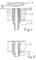
- a sleeve 2 is positioned in the second sleeve 3 and a tube is positioned in the sleeve 2 such that the tube end I and the sleeve end 2 protrude beyond the second sleeve 3 by the amount.
- a heating plate 4 is directed onto the pipe ends at a distance d from above.
- the tube ends of the tubes I are fused to the sleeve ends of the sleeve 2 and the sleeve ends of the sleeve 2 to the second sleeve 3, as shown in FIG.
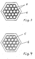
- FIGS. 3 and 4 show a top view of a possible arrangement of tube-sleeve combinations 5 in a second sleeve 6 with a hexagonal cross section, the tube-sleeve combination 5 being shown as a tube for the sake of clarity.
- FIG. 3 This arrangement is shown in FIG. 3 as it is visible before the thermal treatment. After the thermal treatment, the arrangement took on an appearance as shown in FIG. 4.
Abstract
Description
Die Erfindung betrifft einen Wärme- und/oder Stoffaustauscher, bestehend aus mindestens einer Gruppe von Rohren aus thermoplastischem Kunststoff, bei dem die Enden der Rohre stirnseitig verschweißt sind. Ebenso betrifft die Erfindung ein Verfahren zum Herstellen solcher Wärme- und/oder Stoffaustauscher.The invention relates to a heat and / or mass exchanger, consisting of at least one group of tubes made of thermoplastic material, in which the ends of the tubes are welded on the end face. The invention also relates to a method for producing such heat and / or mass exchangers.
Die heute bekannten Wärme- und/oder Stoffaustauscher bestehen aus Rohren oder Rohrgruppen, die aus einem nichtporösen bzw. porösem Material bestehen, und die in einen Rohrboden eingebettet sind. Dieser Rohrboden wird entweder getrennt hergestellt, wobei dann die Rohrenden mit dem Rohrboden verbunden werden müssen, oder der Rohrboden wird zum Herstellen des Wärme- und/oder Stoffaustauschers dadurch erzeugt, daß eine Vergußmasse zwischen die Rohrenden eingebracht wird. Die Herstellung solcher Wärme- und/oder Stoffaustauscher ist aufwendig, weil entweder die Rohre in den Rohrboden eingefädelt und positioniert werden müssen, bevor sie mit dem Rohrboden verbunden werden, oder die Rohrenden mit speziellen Vorrichtungen auf Abstand gehalten werden müssen, um die Vergußmasse (selbstaushärtendes Material oder Kunststoffschmelze) zwischen die Rohre einbringen zu können.The heat and / or mass exchangers known today consist of tubes or tube groups which consist of a non-porous or porous material and which are embedded in a tube sheet. This tube sheet is either manufactured separately, in which case the tube ends must be connected to the tube sheet, or the tube sheet is produced to produce the heat and / or material exchanger by introducing a casting compound between the tube ends. The manufacture of such heat and / or mass exchangers is complex because either the pipes have to be threaded and positioned in the tube sheet before they are connected to the tube sheet, or the tube ends have to be kept at a distance using special devices in order to prevent the casting compound (self-curing Material or plastic melt) between the pipes.
Ein derartiger Wärme- und/oder Stoffaustauscher sowie ein Verfahren zu dessen Herstellung ist beispielsweise aus der US 2 433 546 bekannt. Dort werden die Rohre auf eine Zapfenanordnung einer Pressvorrichtung aufgesteckt und an jeweils beiden Enden durch Niederfahren eines Pressenstempels, der eine weitere Zapfenanordnung aufweist, definiert aufgeweitet und miteinander verschweißt.Such a heat and / or mass exchanger and a method for its production is known for example from US 2,433,546. There, the tubes are plugged onto a pin arrangement of a pressing device and, at both ends, are expanded and welded to one another by moving down a press ram, which has a further pin arrangement.
Aufgabe der vorliegenden Erfindung ist es, einen Wärme- und/oder Stoffaustauscher zur Verfügung zu stellen der einfach herzustellen ist. Außerdem soll der erfindungsgemäße Wärme- und/oder Stoffaustauscher im Bereich des sonst üblichen Rohrbodens sehr kompakt ausgebildet sein. Es ist auch Aufgabe der vorliegenden Erfindung, ein besonders einfach zu "bewerkstelligendes Verfahren zur Herstellung dieser Wärme- und/oder Stoffaustauscher zur Verfügung zu stellen.The object of the present invention is to provide a heat and / or mass exchanger which is simple to manufacture. In addition, the heat and / or mass exchanger according to the invention should be very compact in the area of the otherwise conventional tube sheet. It is also an object of the present invention, an especially easy to "bewerkstelligendes process for preparing these heat and / or mass exchanger to provide.
Diese Aufgabe wird bei einem gattungsgemäßen Wärme- und/oder Stoffaustauscher dadurch gelöst, daß jedes Rohrende einer Gruppe von einer Hülse aus thermoplastischem Kunststoff, die keine Porosität oder höchstens eine Porosität von 20% des Wandvolumens aufweist, umfaßt ist, alle Rohrenden mit Hülsen einer Gruppe von einer zweiten Hülse umfaßt sind, wobei die Hülsen der Rohrenden etwa dieselbe Länge aufweisen wie die zweite Hülse, und daß stirnseitig die Rohrenden jeweils mit dem sie umfassenden Hülsenende, benachbarte Hülsenenden miteinander und außenliegende Hülsenenden mit der zweiten Hülse verschmolzen sind. Ein solcher Wärme- und/oder Stoffaustauscher weist praktisch keinen herkömmlichen Rohrboden mehr auf; die Kombination von Hülsen und Rohrenden macht eine kompakte Anordnung der Rohrenden möglich, ohne daß die am Ende eines Wärme- und/oder Stoffaustauschers erforderliche Festigkeit und Dichtigkeit verloren geht.This object is achieved in a generic heat and / or mass exchanger in that each tube end of a group is surrounded by a sleeve made of thermoplastic material, which has no porosity or at most a porosity of 20% of the wall volume, all tube ends with sleeves of a group are encompassed by a second sleeve, the sleeves of the tube ends having approximately the same length as the second sleeve, and in that the end of the tube ends are fused to the sleeve end comprising them, adjacent sleeve ends to one another and outer sleeve ends to the second sleeve. Such a heat and / or mass exchanger practically no longer has a conventional tube sheet; the combination of sleeves and pipe ends makes a compact arrangement of the pipe ends possible without losing the strength and tightness required at the end of a heat and / or material exchanger.
Bevorzugt bestehen die die Rohrenden umfassenden Hülsen aus einem thermoplastischen Kunststoff, welcher im Bereich zwischen Raumtemperatur und Schmelztemperatur einen mittleren linearen Ausdehnungskoeffizienten zwischen 100 x 10-6 und 400 x 10-61/K besitzt.Preferably, the tube ends comprising the sleeves of a thermoplastic plastic, which has x in the range between room temperature and melting temperature has a mean linear expansion coefficient between 100 x 10- 6 and 400 10-61 / K exist.
In der Regel sind die Rohrenden, die die Rohrenden umfassenden Hülsen und die zweite Hülse mindestens bis zu einer Tiefe, die der dünnsten Wandstärke der Rohre entspricht, miteinander verschmolzen.As a rule, the tube ends, the sleeves comprising the tube ends and the second sleeve are fused together at least to a depth which corresponds to the thinnest wall thickness of the tubes.
Sofern der Außenquerschnitt der Hülsen kreisförmigen oder sechseckigen Querschnitt aufweisen, zeichnet sich der erfindungsgemäße Wärme- und/oder Stoffaustauscher besonders dadurch aus, daß der Innenquerschnitt der zweiten Hülse und der Außenquerschnitt der aus Rohrenden und Hülsen bestehenden Gruppe die Form eines Sechsecks aufweist. Allerdings sind für die zweite Hülse alle Querschnittsformen auch geeignet, bei denen die Rohrenden in kompakter Anordnung in die zweite Hülse eingeführt werden können. Jede Röhrengruppe besteht bevorzugt aus 7 bis 1141 Röhren und somit auch aus 7 bis 1141 Hülsen.If the outer cross section of the sleeves have a circular or hexagonal cross section, the heat and / or material exchanger according to the invention is particularly characterized in that the inner cross section of the second sleeve and the outer cross section of the group consisting of tube ends and sleeves have the shape of a hexagon. However, all cross-sectional shapes in which the tube ends can be inserted into the second sleeve in a compact arrangement are also suitable for the second sleeve. Each tube group preferably consists of 7 to 1141 tubes and thus also from 7 to 1141 sleeves.
Unter dem Begriff Rohre sind im Sinne der Erfindung zusammengefaßt alle rohrförmigen Körper, wie beispielsweise Rohre, Schläuche oder Hohlfäden. Die Querschnittsform der Rohre ist nicht auf kreisförmige Querschnitte beschränkt; die Rohre können auch elliptischen oder vieleckigen, beispielsweise dreieckigen, viereckigen, quadratischen, fünfeckigen usw. Querschnitt aufweisen. Die Wandstärke der Rohre, die sich aufgrund des Außen- und Innenquerschnitts der Rohre ergibt, kann über den Umfang der Rohre gleich oder unterschiedlich sein. Außen- und Innenquerschnitt der Rohre können dieselbe oder verschiedene Querschnittsform aufweisen. Beispielsweise kann ein Rohr im Außenquerschnitt eine vieleckige Kontur und im Innenquerschnitt eine kreisförmige oder elliptische Kontur aufweisen. Auch kann der Innenquerschnitt der Rohre einen oder mehrere durchgehende Hohlräume aufweisen. Es kann aber auch ein einzelnes Rohr aus mehreren Einzelrohren zusammengesetzt sein. Diese Einzelrohre können beispielsweise achsparallel nebeneinanderliegen und die Achsen auf einer geraden Linie angeordnet sein.Within the meaning of the invention, the term tubes includes all tubular bodies, such as tubes, hoses or hollow fibers. The cross-sectional shape of the tubes is not limited to circular cross-sections; the tubes can also have an elliptical or polygonal cross section, for example triangular, square, square, pentagonal, etc. The wall thickness of the pipes, which results from the outside and inside cross section of the pipes, can be the same or different over the circumference of the pipes. Outside and inside cross-section of the tubes can have the same or different cross-sectional shape. For example, a tube may have a polygonal contour in the outer cross section and a circular or elliptical contour in the inner cross section. The inner cross section of the tubes can also have one or more continuous cavities. However, a single tube can also be composed of several individual tubes. These individual tubes can, for example, lie next to one another parallel to the axis and the axes can be arranged on a straight line.
Bevorzugt besteht jede Hülse wie auch die zweite Hülse aus thermoplastischem Polymer, welches zu den Fluorpolymeren gehört. Als weitere bevorzugte Polymerwerkstoffe für die Hülsen wie auch für die zweiten Hülsen kommen Polyäthylen bzw. Polypropylen infrage. Hierbei hat es sich als besonders zweckmäßig erwiesen, wenn Röhrenwerkstoff und Hülsenwerkstoff denselben oder nahezu denselben Schmelzpunkt bzw. Schmelzbereich aufweisen. Zweckmäßig ist es, wenn die Rohre, die Hülsen und die zweiten Hülsen aus thermoplastischen Polymeren bestehen, die von ihrer Grundstruktur zu derselben Polymersorte gehören.Each sleeve, like the second sleeve, is preferably made of thermoplastic polymer, which belongs to the fluoropolymers. Polyethylene or polypropylene are possible as further preferred polymer materials for the sleeves as well as for the second sleeves. It has proven particularly expedient here if the tube material and the sleeve material have the same or almost the same melting point or melting range. It is useful if the tubes, the sleeves and the second sleeves consist of thermoplastic polymers, which belong to the same type of polymer from their basic structure.
Ein erfindungsgemäßer Wärmeaustauscher zeichnet sich dadurch aus, daß die Rohre eine Porosität von maximal 20% des Wandvolumens aufweisen. Ein erfindungsgemäßer Stoffaustauscher zeichnet sich dadurch aus, daß die Rohre eine Porosität von bis zu 90% des Wandvolumens aufweisen. Ein solcher Stoffaustauscher kann je nach Einsatzzweck zusätzlich auch die Funktion eines Wärmetauschers erfüllen.A heat exchanger according to the invention is characterized in that the tubes have a porosity of at most 20% of the wall volume. A material exchanger according to the invention is characterized in that the tubes have a porosity of up to 90% of the wall volume. Depending on the application, such a material exchanger can also perform the function of a heat exchanger.
Die erfindungsgemäß gestellte Aufgabe wird auch gelöst durch ein Verfahren zum Herstellen eines Wärme- und/oder Stoffaustauschers gemäß der Erfindung, welches sich dadurch auszeichnet, daß jedes Rohrende in jeweils einer Hülse positioniert wird, daß die Rohrenden zumindest einer Seite der Rohre mit den Hülsen zusammengefaßt und derart in der zweiten Hülse positioniert werden, daß die Rohrenden und die Hülsenenden zumindest nahezu vertikal nach oben, mit der zweiten Hülse bündig oder die zweite Hülse bis zu 4 mm überragend angeordnet sind, und Rohrenden und Hülsenenden eine im wesentlichen ebene Fläche bilden, daß dann von oben her den Rohrenden soviel Wärme zugeführt wird, daß die Rohrenden mit den Hülsenenden verschmelzen und die Hülsenenden sich derart erweitern, daß diese sich an die Außenwände benachbarter Hülsen bzw. an die zweite Hülse anlegen und mit diesen Hülsenenden bzw. Enden der zweiten Hülse verschmelzen.The object of the invention is also achieved by a method for producing a heat and / or mass exchanger according to the invention, which is characterized in that each tube end is positioned in a sleeve, that the tube ends combine at least one side of the tubes with the sleeves and positioned in the second sleeve such that the tube ends and the sleeve ends are at least almost vertically upward, flush with the second sleeve or the second sleeve protrudes up to 4 mm, and tube ends and sleeve ends form a substantially flat surface that then so much heat is supplied to the tube ends from above that the tube ends merge with the sleeve ends and the sleeve ends expand in such a way that they abut on the outer walls of adjacent sleeves or on the second sleeve and with these sleeve ends or ends of the second sleeve merge.
In der Regel wird die thermische Behandlung unter Einhaltung folgender Bedingung durchgeführt:
- wobei Q die zugeführte Wärmemenge, pro Fläche (Stirnseite) und Zeit in J/m2 s,
- e der lineare Ausdehnungskoeffizient des Stabmaterials in 1/K,
- t die Zeitdauer der Wärmeeinwirkung in sec.,
- p die Dichte des Stabmaterials in kg/CM 3,
- Cp die spezifische Wärme des Stabmaterials in J/kg K, und
- λ die Wärmeleitfähigkeit des Stabmaterials in J/msK
- where Q is the amount of heat supplied, per surface (end face) and time in J / m 2 s,
- e is the linear expansion coefficient of the rod material in 1 / K,
- t the duration of the heat in seconds,
- p the density of the rod material in kg / CM 3 ,
- Cp is the specific heat of the rod material in J / kg K, and
- λ is the thermal conductivity of the rod material in J / msK
Das erfindungsgemäße Verfahren gelingt vorzüglich,wenn Hülsen aus einem thermoplastischen Werkstoff verwendet werden, welcher im Bereich zwischen Raumtemperatur und Schmelztemperatur einen mittleren linearen Ausdehnungskoreffizienten zwischen 100 x 10-6 und 400 x iO-6 1/K besitzt.The method according to the invention succeeds particularly well when sleeves are used made of a thermoplastic material which x in the range between room temperature and melting temperature has a mean linear Ausdehnungskoreffizienten between 100 x 10- 6 and 400
Bevorzugt werden Hülsen- und/oder Rohrenden auf eine Temperatur, die oberhalb der Schmelztemperatur des Rohr- bzw. Hülsenmaterials liegt, erhitzt.The sleeve and / or tube ends are preferably heated to a temperature which is above the melting temperature of the tube or sleeve material.
Es hat sich bei dem erfindungsgemäßen Verfahren als vorteilhaft herausgestellt, wenn die Hülsenenden und die Rohrenden vor der thermischen Behandlung derart in der Öffnung der zweiten Hülse positioniert werden, daß die Rohrenden und die Hülsenenden die zweite Hülse 0,5 bis 3 mm überragen.It has proven to be advantageous in the method according to the invention if the sleeve ends and the tube ends are positioned in the opening of the second sleeve before the thermal treatment in such a way that the tube ends and the sleeve ends protrude 0.5 to 3 mm beyond the second sleeve.
Das erfindungsgemäße Verfahren gelingt vorzüglich, wenn die Hülsenenden zu einer kompakten Packung zusammengefaßt werden, bevor ihnen Wärme zugeführt wird.The method according to the invention is particularly successful if the sleeve ends are combined into a compact package before heat is supplied to them.
Ebenfalls hat es sich als besonders vorteilhaft herausgestellt, wenn Rohre verwendet werden, deren hydraulischer Durchmesser zwischen 0,3 und 15mm, vorzugsweise zwischen 0,5 und 7,5 mm liegt, und deren Wandstärke an der dünnsten Stelle zwischen 5 und 25%, vorzugsweise zwischen 7,5 und 17,5% des hydraulischen Durchmessers liegt.It has also turned out to be particularly advantageous if tubes are used whose hydraulic diameter is between 0.3 and 15 mm, preferably between 0.5 and 7.5 mm, and whose wall thickness at the thinnest point is between 5 and 25%, preferably is between 7.5 and 17.5% of the hydraulic diameter.
Die Wärmezufuhr erfolgt in der Regel durch Wärmestrahlung. Bei Wärmestrahlung kann die Wärmezufuhr in einfachster Weise dadurch erreicht werden, daß eine Heizplatte von oben her auf die Rohrenden zubewegt wird, und in einem Abstand, der im Bereich von 0,5 bis 30 mm liegt, solange positioniert wird, bis die Rohrenden mit den Hülsen und die Hülsen miteinander bzw. mit der zweiten Hülse verschmolzen sind. Man kann die thermische Behandlung auch unter Vakuum oder unter einer Schutzgasathmosphäre durchführen, wobei dann der Abstand der Heizplatte in anderen Bereichen liegen kann.The heat is usually supplied by heat radiation. In the case of heat radiation, the supply of heat can be achieved in the simplest manner by moving a heating plate from above onto the pipe ends and at a distance which is in the range from 0.5 to 30 mm until the pipe ends are positioned with the Sleeves and the sleeves are fused together or with the second sleeve. The thermal treatment can also be carried out under vacuum or under a protective gas atmosphere, in which case the distance between the heating plate can be in other areas.
Die Erfindung wird anhand eines Beispiels näher erläutert.The invention is explained in more detail using an example.
Die Eigenschaften der in dem nachfolgenden Beispiel verwendeten Kunststoff sind in der Tabelle zusammengestellt.

Ein Bündel von 91 Röhren aus PVDF Typ I, die einen Außendurchmesser von 2 mm und eine Wandstärke von 0,1 mm aufweisen, werden derart zusammengefügt, daß sie in eine sechseckige Öffnung einer Hülse aus PVDF Typ II mit einer Länge von 30 mm eingeführt werden können. Jede Seite der sechseckigen Öffnung der Hülse weist eine Länge von 12 mm auf, wobei alle Eckpunkte des Sechseckes auf einem Kreis liegen. Die Wände der sechseckigen Öffnung sind derart abgeschrägt, daß die Abschrägungen gegenüberliegender Wände einen Winkel von 90° einschließen und die Abschrägung bis zu einer Tiefe von 1,25 mm reicht. Die Röhren weisen eine Länge auf, die der Länge der Hülse entsprechen und sind derart in der Hülse positioniert, daß sie stirnseitig mit der Hülse bündig eine ebene Fläche bilden. In jeder Röhre wird nun jeweils ein Rohrende einer weiteren Röhre positioniert, wobei diese Röhren aus PVDF Typ bestehen, einen Außendurchmesser von 1,5 mm, eine Wandstärke von 0,25 mm und eine Porosität von 50% des Wandvolumens aufweisen. Die Rohrenden dieser zweiten Röhren werden derart positioniert, daß sie zur Stirnseite hin mit den ersten Röhren, den Hülsen bündig abschließen.A bundle of 91 tubes of PVDF type I, which have an outer diameter of 2 mm and a wall thickness of 0.1 mm, are put together in such a way that they are inserted into a hexagonal opening of a sleeve made of PVDF type II with a length of 30 mm can. Each side of the hexagonal opening of the sleeve has a length of 12 mm, with all the corner points of the hexagon lying on a circle. The walls of the hexagonal opening are chamfered in such a way that the chamfers on opposite walls enclose an angle of 90 ° and the chamfer extends to a depth of 1.25 mm. The tubes have a length which corresponds to the length of the sleeve and are positioned in the sleeve in such a way that they form a flat surface on the end face, flush with the sleeve. One tube end of another tube is now positioned in each tube, these tubes being made of PVDF type, having an outer diameter of 1.5 mm, a wall thickness of 0.25 mm and a porosity of 50% of the wall volume. The tube ends of these second tubes are positioned in such a way that they end flush with the sleeves on the front side with the first tubes.
Eine runde Heizplatte mit einem Durchmesser von 100 mm, die einen Emissionskoeffizienten von 0,9 besitzt und auf eine Temperatur von 430°C erhitzt ist, wird 2 Minuten lang in einem Abstand von 10 mm über die im wesentlichen vertikal positionierten Rohr- und Hülsenenden gehalten. Nach dem Abkühlen kann man feststellen, daß alle Hülsen miteinander bzw. mit der Hülse über eine Tiefe von der Stirnseite her von I mm miteinander verschmolzen sind, wobei gleichzeitig jedes Rohrende mit dem Hülsenende über eine Tiefe von 2 mm verschmolzen ist.A round heating plate with a diameter of 100 mm, which has an emission coefficient of 0.9 and is heated to a temperature of 430 ° C., is held for 2 minutes at a distance of 10 mm above the essentially vertically positioned pipe and sleeve ends . After cooling, it can be seen that all sleeves are fused to one another or to the sleeve over a depth of 1 mm from the end face, with each tube end being fused to the sleeve end over a depth of 2 mm.
Die Erfindung wird auch anhand von Figuren näher erläutert.The invention is also explained in more detail with reference to figures.
Es zeigen:
- Figur I den Querschnitt durch ein Rohrende, welches in einer Hülse, und diese Hülse in einer zweiten Hülse positioniert ist, vor der thermischen Behandlung,
Figur 2 den Querschnitt der in Figur I dargestellten Anordnung nach der thermischen Behandlung,Figur 3 die Draufsicht einer Anordnung von Rohrenden vor der thermischen Behandlung,Figur 4 dieDraufsicht gemäß Figur 3 nach der thermischen Behandlung.
- FIG. 1 shows the cross section through a pipe end, which is positioned in a sleeve, and this sleeve is positioned in a second sleeve, before the thermal treatment,
- FIG. 2 shows the cross section of the arrangement shown in FIG. 1 after the thermal treatment,
- FIG. 3 the top view of an arrangement of pipe ends before the thermal treatment,
- 4 shows the top view according to FIG. 3 after the thermal treatment.
In Figur ist in der zweiten Hülse 3 eine Hülse 2, und in der Hülse 2 ein Rohr jeweils derart positioniert, daß Rohrende I und Hülsenende 2 die zweite Hülse 3 um den Betrag Süberragen. Zur thermischen Behandlung wird eine Heizplatte 4 in einem Abstand d von oben her auf die Rohrenden gerichtet.In the figure, a
Nach der thermischen Behandlung sind die Rohrenden der Rohre I mit den Hülsenenden der Hülse 2 und die Hülsenenden der Hülse 2 mit der zweiten Hülse 3 verschmolzen, wie in Figur 2 dargestellt.After the thermal treatment, the tube ends of the tubes I are fused to the sleeve ends of the
Der Einfachheit halber ist in den Figuren und 2 nur jeweils ein Rohrende I und eine Hülse 2 dargestellt.For the sake of simplicity, only one pipe end I and one
In den Figuren 3 und 4 ist in Draufsicht eine mögliche Anordnung von Rohr-Hülsenkombinationen 5 in einer zweiten Hülse 6 mit sechseckigem Querschnitt dargestellt, wobei zum Zwecke der Übersichtlichkeit die Rohr-Hülsenkombination 5 als ein Rohr dargestellt wurde.FIGS. 3 and 4 show a top view of a possible arrangement of tube-
In Figur 3 ist diese Anordnung gezeigt, wie sie vor der thermischen Behandlung sichtbar ist. Nach der thermischen Behandlung hat die Anordnung ein Aussehen angenommen, wie sie in Figur 4 dargestellt ist.This arrangement is shown in FIG. 3 as it is visible before the thermal treatment. After the thermal treatment, the arrangement took on an appearance as shown in FIG. 4.
Ein Ende einer Rohrhülsenkombination 5, welches mit sechs benachbarten Rohrhülsenkombinationen verschmolzen ist, weist stirnseitig (in Draufsicht) eine sechseckige Kontur auf. Ein Ende einer Rohrhülsenkombination, die der zweiten Hülse 6 benachbart angeordnet ist, weist eine Kontur auf, die durch ein Fünfeck mit verschiedenen Eckwinkeln und Seitenlängen beschrieben werden kann, wobei die Fünfecke der Kontur der Enden der Rohrhülsenkombinationen derart aufgebaut sind, daß die Konturlinie zwischen zwei Rohrhülsenkombinationen mit einer zweiten Konturlinie zwischen zwei Rohrhülsenkombinationen einen Winkel von 120°, mit einer Konturlinie zwischen Rohrhülsenkombination und zweiter Hülse jedoch einen Winkel von 90° einschließen.One end of a tube-
Claims (20)

Priority Applications (1)
| Application Number | Priority Date | Filing Date | Title |
|---|---|---|---|
| AT87100394T ATE53450T1 (en) | 1986-04-28 | 1987-01-14 | HEAT AND/OR MASS EXCHANGER AND METHOD OF MAKING HEAT AND/OR MASS EXCHANGER. |
Applications Claiming Priority (2)
| Application Number | Priority Date | Filing Date | Title |
|---|---|---|---|
| DE19863614342 DE3614342A1 (en) | 1986-04-28 | 1986-04-28 | HEAT AND / OR FABRIC EXCHANGER AND METHOD FOR PRODUCING HEAT AND / OR FABRIC EXCHANGER |
| DE3614342 | 1986-04-28 |
Publications (3)
| Publication Number | Publication Date |
|---|---|
| EP0243575A2 EP0243575A2 (en) | 1987-11-04 |
| EP0243575A3 EP0243575A3 (en) | 1988-10-19 |
| EP0243575B1 true EP0243575B1 (en) | 1990-06-06 |
Family
ID=6299702
Family Applications (1)
| Application Number | Title | Priority Date | Filing Date |
|---|---|---|---|
| EP87100394A Expired - Lifetime EP0243575B1 (en) | 1986-04-28 | 1987-01-14 | Heat and/or mass exchanger, and method of producing a heat and/or mass exchanger |
Country Status (5)
| Country | Link |
|---|---|
| US (1) | US4834930A (en) |
| EP (1) | EP0243575B1 (en) |
| JP (1) | JPS62266393A (en) |
| AT (1) | ATE53450T1 (en) |
| DE (2) | DE3614342A1 (en) |
Cited By (1)
| Publication number | Priority date | Publication date | Assignee | Title |
|---|---|---|---|---|
| DE102005004372A1 (en) * | 2005-01-31 | 2006-08-10 | Wat-Membratec Gmbh & Co Kg | Method for connecting porous membranes and membrane filter device produced thereby |
Families Citing this family (16)
| Publication number | Priority date | Publication date | Assignee | Title |
|---|---|---|---|---|
| DE3728303A1 (en) * | 1987-08-25 | 1989-03-16 | Sueddeutsche Kuehler Behr | HEAT EXCHANGER WITH A RIB TUBE ARRANGEMENT |
| DE3806517A1 (en) * | 1988-03-01 | 1989-09-14 | Akzo Gmbh | PIPE BOTTOM FOR HEAT AND / OR FUEL EXCHANGERS, THE USE THEREOF AND THE METHOD FOR THE PRODUCTION THEREOF |
| EP0373102A3 (en) * | 1988-11-09 | 1990-08-08 | Jäggi AG Bern | Heat exchanger and method for its manufacture |
| SE469855B (en) * | 1992-02-06 | 1993-09-27 | Bjoern Hagert C O Aalander | Method of manufacturing plastic heat exchangers by heat fusion of duct plates end portions and spacers |
| US6001291A (en) * | 1996-02-07 | 1999-12-14 | Cesaroni; Anthony Joseph | Method of bonding tubes into an article |
| JP3059393B2 (en) * | 1996-11-26 | 2000-07-04 | 日本ピラー工業株式会社 | Heat exchanger |
| US20030029040A1 (en) * | 1999-03-08 | 2003-02-13 | Cesaroni Anthony Joseph | Laser bonding of heat exchanger tubes |
| US6189768B1 (en) * | 1999-05-27 | 2001-02-20 | Columbian Chemicals Company | Process and apparatus for pressing an external sleeve onto a tube for enhancing weld design |
| US6557266B2 (en) | 2001-09-17 | 2003-05-06 | John Griffin | Conditioning apparatus |
| CN1922461B (en) * | 2003-12-22 | 2012-12-26 | 安格斯公司 | Potted exchange devices and methods of making |
| CA2538761A1 (en) * | 2005-03-08 | 2006-09-08 | Anthony Joseph Cesaroni | Method for sealing heat exchanger tubes |
| WO2014164501A1 (en) | 2013-03-12 | 2014-10-09 | Lockheed Martin Corporation | Process of friction stir welding on tube end joints and a product produced thereby |
| FR3006232A1 (en) * | 2013-05-28 | 2014-12-05 | Bieder Alexandra Singer | PROCESS FOR ASSEMBLING PLASTIC TUBES FROM A SOURCE OF HEAT PERMITTING BY AUTOGENIC WELDING, OBTAINING A HOMOGENEOUS MATERIAL WITH AESTHETIC, MECHANICAL AND LIGHT QUALITIES |
| DE102017100460A1 (en) * | 2017-01-11 | 2018-07-12 | Hanon Systems | Device for heat transfer in a refrigerant circuit |
| CN106949776A (en) * | 2017-04-28 | 2017-07-14 | 上海金由氟材料股份有限公司 | PTFE tube ends fixed structure and method in a kind of heat exchanger |
| CN106949777A (en) * | 2017-04-28 | 2017-07-14 | 上海金由氟材料股份有限公司 | The locating connector and method of PTFE heat exchanger tubes in a kind of heat exchanger |
Family Cites Families (42)
| Publication number | Priority date | Publication date | Assignee | Title |
|---|---|---|---|---|
| US2433546A (en) * | 1943-12-11 | 1947-12-30 | Richard T Cornelius | Method and apparatus for forming plastic radiator cores |
| US2538808A (en) * | 1950-03-24 | 1951-01-23 | Westinghouse Electric Corp | Sealed heater element and the like |
| FR1135923A (en) * | 1954-08-30 | 1957-05-06 | Standard Thomson Corp | Improvements to heat exchanger cores and their manufacturing process |
| SU121029A1 (en) * | 1958-11-29 | 1958-11-30 | К.Р. Янсон | Method of making contact rasters |
| US2966373A (en) * | 1959-02-02 | 1960-12-27 | Ici Ltd | Tubular inserts |
| DE1209725B (en) * | 1960-03-11 | 1966-01-27 | Hans Joachim Dietzsch G M B H | Process for the surface treatment of a body made of bundled hollow threads |
| DE1238621B (en) * | 1963-04-13 | 1967-04-13 | Dom Techniczno Handlowy Przed | Device for cooling or warming the blood during surgical operations |
| US3347728A (en) * | 1964-07-29 | 1967-10-17 | Gen Motors Corp | Method for forming joints in tubes |
| NL151792C (en) * | 1965-01-14 | |||
| US3462362A (en) * | 1966-07-26 | 1969-08-19 | Paul Kollsman | Method of reverse osmosis |
| US3459622A (en) * | 1966-11-07 | 1969-08-05 | Du Pont | Apparatus for the manufacture of plastic tube heat exchanger units |
| US3419069A (en) * | 1967-04-28 | 1968-12-31 | Du Pont | Heat transfer apparatus having flexible plastic tubular elements arranged in a braided configuration |
| US3435893A (en) * | 1967-07-31 | 1969-04-01 | Du Pont | Heat exchanger component formed with flexible plastic tubes |
| US3438434A (en) * | 1967-10-19 | 1969-04-15 | Du Pont | Subdivided heat exchanger tube bundle assembly providing longitudinally distributed fluid bypass and distributing channels |
| US3616022A (en) * | 1968-08-06 | 1971-10-26 | Du Pont | Method of making heat exchange components |
| US3592261A (en) * | 1968-11-25 | 1971-07-13 | Lummus Co | Heat exchanger |
| US3529664A (en) * | 1969-04-23 | 1970-09-22 | Du Pont | End structure for thermoplastic tubing |
| BE755779A (en) * | 1969-09-05 | 1971-02-15 | Westinghouse Electric Corp | APPARATUS FOR REVERSE OSMOSIS AND METHOD FOR MANUFACTURING IT |
| FR2088805A5 (en) * | 1970-04-24 | 1972-01-07 | Fabr Element Catalytiq | |
| US3708069A (en) * | 1970-08-13 | 1973-01-02 | Aqua Chem Inc | Reverse osmosis membrane module and apparatus using the same |
| US3848660A (en) * | 1970-08-17 | 1974-11-19 | Du Pont | Plastic heat exchange apparatus and a method for making |
| US3718181A (en) * | 1970-08-17 | 1973-02-27 | Du Pont | Plastic heat exchange apparatus |
| GB1354502A (en) * | 1970-08-28 | 1974-06-05 | Ici Ltd | Heat exchangers |
| US3741849A (en) * | 1971-02-08 | 1973-06-26 | Angelica Corp | Method of joining tubes to manifold |
| DE2204167A1 (en) * | 1972-01-29 | 1973-08-09 | Krupp Gmbh | HEAT EXCHANGER AND PROCESS FOR ITS MANUFACTURING |
| DE2221951C2 (en) * | 1972-04-27 | 1983-04-28 | The Dow Chemical Co., 48640 Midland, Mich. | Membrane unit for cleaning a liquid mixture using reverse osmosis |
| FR2191091B1 (en) * | 1972-07-04 | 1975-03-07 | Rhone Poulenc Ind | |
| US4098852A (en) * | 1972-07-04 | 1978-07-04 | Rhone-Poulenc, S.A. | Process for carring out a gas/liquid heat-exchange |
| GB1478015A (en) * | 1973-07-27 | 1977-06-29 | Delanair Ltd | Heat exchanger |
| FR2273222B1 (en) * | 1974-05-30 | 1977-10-07 | Chausson Usines Sa | |
| DD121029A2 (en) * | 1975-06-19 | 1976-07-12 | ||
| GB1497204A (en) * | 1976-01-20 | 1978-01-05 | Kato M | Method for bundling tubes |
| US4047563A (en) * | 1976-01-27 | 1977-09-13 | Japan Medical Supply Co., Ltd. | Heat exchanger for artificial heart and lung devices |
| DE2603615C3 (en) * | 1976-01-30 | 1979-06-13 | Masashi Daito Osaka Kato (Japan) | Device for producing a tube bundle from thermoplastic material |
| DE2612514B1 (en) * | 1976-03-24 | 1977-09-29 | Cenrus Ag | TUBE FLOOR OF A PIPE HEAT EXCHANGER |
| DE2734958A1 (en) * | 1977-08-03 | 1979-02-15 | Froehlich Air Ag | PROCESS FOR MANUFACTURING A PIPE HEAT EXCHANGER AND PIPE HEAT EXCHANGER MANUFACTURED BY THIS PROCESS |
| US4177816A (en) * | 1978-03-27 | 1979-12-11 | Sci-Med Life Systems, Inc. | Heat exchanger for blood |
| US4300971A (en) * | 1979-04-23 | 1981-11-17 | Mcalister Roy E | Method for manifolding multiple passage solar panel |
| US4481057A (en) * | 1980-10-28 | 1984-11-06 | Oximetrix, Inc. | Cutting device and method of manufacture |
| DE3240143A1 (en) * | 1982-10-29 | 1984-05-03 | Akzo Gmbh, 5600 Wuppertal | Process for embedding membranes in a thermoplastic material |
| DE3338157A1 (en) * | 1983-10-20 | 1985-05-02 | Akzo Gmbh, 5600 Wuppertal | METHOD FOR SEALINGLY CONNECTING PIPE ENDS IN PIPE BASES |
| CA1259870A (en) * | 1984-10-01 | 1989-09-26 | Eiichi Hamada | Heat exchanger and blood oxygenating device furnished therewith |
-
1986
- 1986-04-28 DE DE19863614342 patent/DE3614342A1/en not_active Withdrawn
-
1987
- 1987-01-14 DE DE8787100394T patent/DE3763110D1/en not_active Expired - Fee Related
- 1987-01-14 EP EP87100394A patent/EP0243575B1/en not_active Expired - Lifetime
- 1987-01-14 AT AT87100394T patent/ATE53450T1/en not_active IP Right Cessation
- 1987-03-10 US US07/024,179 patent/US4834930A/en not_active Expired - Fee Related
- 1987-04-27 JP JP62102156A patent/JPS62266393A/en active Pending
Cited By (2)
| Publication number | Priority date | Publication date | Assignee | Title |
|---|---|---|---|---|
| DE102005004372A1 (en) * | 2005-01-31 | 2006-08-10 | Wat-Membratec Gmbh & Co Kg | Method for connecting porous membranes and membrane filter device produced thereby |
| DE102005004372B4 (en) * | 2005-01-31 | 2008-01-17 | Wat-Membratec Gmbh & Co Kg | Method for connecting porous membranes and membrane filter device produced thereby |
Also Published As
| Publication number | Publication date |
|---|---|
| US4834930A (en) | 1989-05-30 |
| ATE53450T1 (en) | 1990-06-15 |
| DE3614342A1 (en) | 1987-10-29 |
| EP0243575A3 (en) | 1988-10-19 |
| DE3763110D1 (en) | 1990-07-12 |
| JPS62266393A (en) | 1987-11-19 |
| EP0243575A2 (en) | 1987-11-04 |
Similar Documents
| Publication | Publication Date | Title |
|---|---|---|
| EP0243575B1 (en) | Heat and/or mass exchanger, and method of producing a heat and/or mass exchanger | |
| EP0243574B1 (en) | Heat exchanger and method of producing heat exchangers | |
| EP0226825B1 (en) | Method of joining hollow profiles and a plastics plate together, especially for manufacturing heat exchangers | |
| DE2313565B2 (en) | Method of manufacturing a tube bundle for heat exchangers and tube bundles manufactured using the method | |
| DE2814595C2 (en) | Method for manufacturing a pipe from thermoplastic material | |
| DE3104010A1 (en) | HEAT EXCHANGER TUBE AND HEAT EXCHANGER WITH COLLECTING PLATE AND MECHANICAL ASSEMBLY WITH THE HEAT EXCHANGER TUBE | |
| DE4343825A1 (en) | Pipe-floor connection for a heat exchanger | |
| EP2159366B1 (en) | Method and device for producing a square spacer frame for insulating glass panes | |
| DE4334203C2 (en) | Tool for inserting passages in a header pipe of a heat exchanger | |
| DE4223508A1 (en) | Reinforcement mat for plaster layers of buildings | |
| DE2325245B2 (en) | Method of manufacturing a secondary electron-emitting microchannel plate | |
| CH644444A5 (en) | HEAT EXCHANGER. | |
| WO2007088072A1 (en) | Connection between the end side of a plastic pipe and a plastic body | |
| CH648402A5 (en) | HEAT EXCHANGER. | |
| DE102013012611B4 (en) | Form for the production of a pipe consisting of interconnectable layers and method for its production | |
| DE2540202C2 (en) | radiator | |
| DE4303396A1 (en) | Pressing perforated objects | |
| DE102014108975A1 (en) | Method for producing structured pipe sections and device for carrying out the method | |
| DE2447652A1 (en) | TUBULAR PLATE ELECTRODE AND METHOD OF MANUFACTURING THEREOF | |
| DE2758134C2 (en) | Process for the production of heat exchanger tubes!) With inner and outer longitudinal ribs | |
| DE3636177A1 (en) | Process, in particular for producing a heat exchanger, and a heat exchanger | |
| DE4443270C2 (en) | Process for producing molded parts for chimney pipes or the like and press for carrying out the process | |
| CH673421A5 (en) | Heating radiator production method - presses flat tubes inwards at curved edges for pressure-welding to manifolds | |
| DE2016581A1 (en) | Method and device for calibrating continuously extruded plastic pipe bodies | |
| EP0798526A2 (en) | Heating element, more particularly radiator |
Legal Events
| Date | Code | Title | Description |
|---|---|---|---|
| PUAI | Public reference made under article 153(3) epc to a published international application that has entered the european phase |
Free format text: ORIGINAL CODE: 0009012 |
|
| AK | Designated contracting states |
Kind code of ref document: A2 Designated state(s): AT BE CH DE ES FR GB GR IT LI LU NL SE |
|
| PUAL | Search report despatched |
Free format text: ORIGINAL CODE: 0009013 |
|
| AK | Designated contracting states |
Kind code of ref document: A3 Designated state(s): AT BE CH DE ES FR GB GR IT LI LU NL SE |
|
| 17P | Request for examination filed |
Effective date: 19881108 |
|
| 17Q | First examination report despatched |
Effective date: 19890315 |
|
| GRAA | (expected) grant |
Free format text: ORIGINAL CODE: 0009210 |
|
| AK | Designated contracting states |
Kind code of ref document: B1 Designated state(s): AT BE CH DE ES FR GB GR IT LI LU NL SE |
|
| PG25 | Lapsed in a contracting state [announced via postgrant information from national office to epo] |
Ref country code: BE Effective date: 19900606 Ref country code: FR Effective date: 19900606 Ref country code: GB Effective date: 19900606 Ref country code: GR Free format text: LAPSE BECAUSE OF FAILURE TO SUBMIT A TRANSLATION OF THE DESCRIPTION OR TO PAY THE FEE WITHIN THE PRESCRIBED TIME-LIMIT Effective date: 19900606 Ref country code: IT Free format text: LAPSE BECAUSE OF FAILURE TO SUBMIT A TRANSLATION OF THE DESCRIPTION OR TO PAY THE FEE WITHIN THE PRE;WARNING: LAPSES OF ITALIAN PATENTS WITH EFFECTIVE DATE BEFORE 2007 MAY HAVE OCCURRED AT ANY TIME BEFORE 2007. THE CORRECT EFFECTIVE DATE MAY BE DIFFERENT FROM THE ONE RECORDED.SCRIBED TIME-LIMIT Effective date: 19900606 |
|
| REF | Corresponds to: |
Ref document number: 53450 Country of ref document: AT Date of ref document: 19900615 Kind code of ref document: T |
|
| REF | Corresponds to: |
Ref document number: 3763110 Country of ref document: DE Date of ref document: 19900712 |
|
| PG25 | Lapsed in a contracting state [announced via postgrant information from national office to epo] |
Ref country code: ES Free format text: LAPSE BECAUSE OF FAILURE TO SUBMIT A TRANSLATION OF THE DESCRIPTION OR TO PAY THE FEE WITHIN THE PRESCRIBED TIME-LIMIT Effective date: 19900917 |
|
| EN | Fr: translation not filed | ||
| GBV | Gb: ep patent (uk) treated as always having been void in accordance with gb section 77(7)/1977 [no translation filed] | ||
| PG25 | Lapsed in a contracting state [announced via postgrant information from national office to epo] |
Ref country code: AT Effective date: 19910114 |
|
| PG25 | Lapsed in a contracting state [announced via postgrant information from national office to epo] |
Ref country code: SE Effective date: 19910115 |
|
| PG25 | Lapsed in a contracting state [announced via postgrant information from national office to epo] |
Ref country code: LU Free format text: LAPSE BECAUSE OF NON-PAYMENT OF DUE FEES Effective date: 19910131 Ref country code: CH Effective date: 19910131 Ref country code: LI Effective date: 19910131 |
|
| PLBE | No opposition filed within time limit |
Free format text: ORIGINAL CODE: 0009261 |
|
| STAA | Information on the status of an ep patent application or granted ep patent |
Free format text: STATUS: NO OPPOSITION FILED WITHIN TIME LIMIT |
|
| 26N | No opposition filed | ||
| PG25 | Lapsed in a contracting state [announced via postgrant information from national office to epo] |
Ref country code: NL Effective date: 19910801 |
|
| NLV4 | Nl: lapsed or anulled due to non-payment of the annual fee | ||
| REG | Reference to a national code |
Ref country code: CH Ref legal event code: PL |
|
| PG25 | Lapsed in a contracting state [announced via postgrant information from national office to epo] |
Ref country code: DE Effective date: 19911001 |
|
| EUG | Se: european patent has lapsed |
Ref document number: 87100394.3 Effective date: 19910910 |