EP0242946A2 - Calibration of combined oxygen and combustibles analyses - Google Patents
Calibration of combined oxygen and combustibles analyses Download PDFInfo
- Publication number
- EP0242946A2 EP0242946A2 EP87301222A EP87301222A EP0242946A2 EP 0242946 A2 EP0242946 A2 EP 0242946A2 EP 87301222 A EP87301222 A EP 87301222A EP 87301222 A EP87301222 A EP 87301222A EP 0242946 A2 EP0242946 A2 EP 0242946A2
- Authority
- EP
- European Patent Office
- Prior art keywords
- combustibles
- analyser
- oxygen
- signal
- unit
- Prior art date
- Legal status (The legal status is an assumption and is not a legal conclusion. Google has not performed a legal analysis and makes no representation as to the accuracy of the status listed.)
- Granted
Links
Images

Classifications
-
- G—PHYSICS
- G01—MEASURING; TESTING
- G01N—INVESTIGATING OR ANALYSING MATERIALS BY DETERMINING THEIR CHEMICAL OR PHYSICAL PROPERTIES
- G01N35/00—Automatic analysis not limited to methods or materials provided for in any single one of groups G01N1/00 - G01N33/00; Handling materials therefor
-
- G—PHYSICS
- G01—MEASURING; TESTING
- G01N—INVESTIGATING OR ANALYSING MATERIALS BY DETERMINING THEIR CHEMICAL OR PHYSICAL PROPERTIES
- G01N33/00—Investigating or analysing materials by specific methods not covered by groups G01N1/00 - G01N31/00
- G01N33/0004—Gaseous mixtures, e.g. polluted air
- G01N33/0006—Calibrating gas analysers
-
- G—PHYSICS
- G01—MEASURING; TESTING
- G01N—INVESTIGATING OR ANALYSING MATERIALS BY DETERMINING THEIR CHEMICAL OR PHYSICAL PROPERTIES
- G01N27/00—Investigating or analysing materials by the use of electric, electrochemical, or magnetic means
- G01N27/26—Investigating or analysing materials by the use of electric, electrochemical, or magnetic means by investigating electrochemical variables; by using electrolysis or electrophoresis
- G01N27/416—Systems
- G01N27/417—Systems using cells, i.e. more than one cell and probes with solid electrolytes
- G01N27/4175—Calibrating or checking the analyser
Definitions
- This invention relates to the calibration of combined oxygen and combustibles analysers.
- Thermocouples and infra-red gas analysers are two systems used to monitor pulverisers.
- a shield is needed to protect these systems from the corrosive coal particles in the coal pulveriser.
- the shield reduces heat conduction to the thermocouple system, thereby reducing response time.
- Infra-red gas analysers need to condition the sample gas, also decreasing response time and sensitivity.
- a more reliable method used to monitor volatile atmospheres in coal pulverisers is to provide signals indicative of either oxygen, CO, or both. A certain quantity of each of these elements in a volatile atmosphere becomes indicative of the presence of a hazardous condition.
- Combination oxygen/combustibles analysers such as the Model OL230 supplied by Bailey Controls Company, a division of The Babcock & Wilcox Company, are used to provide such signals or combinations of them.
- the present method for calibrating these analysers is manual.
- An operator manually introduces a test gas into the analyser, maintaining the air pressure as if the analyser was in operation.
- calibration potentiometers are manually adjusted and test voltage outputs are monitored by hand-held voltmeters until desired calibrated outputs are attained.
- a known method of calibrating a combustibles signal consists of introducing a test gas into the analyser and maintaining the sample air pressure as in the manual calibration of the oxygen signal. Zero and span (maximum scale value) values from the test gas are adjusted by an operator. The incoming sample signal is then calibrated according to these adjusted values.
- the known calibration systems for combination oxygen/combustibles analysers are also manual. This inhibits the calibration of a plurality of analysers by one operator.
- the oxygen calibration operation requires at least fifteen minutes of operator time. This manual operation introduces the possibility of operator error and does not allow for repeatability of zero and span values. Further, the calibration of both combustibles and oxygen signals is not coordinated and thus hinders a plurality of analysers from being calibrated concurrently.
- the oxygen signal can drift significantly out of calibration before an operator becomes aware of the need for recalibration, a significant error with the oxygen signal is generated by the drift before it is detected and corrected.
- an automatic calibration system for a combined oxygen and combustibles analyser comprising: an analyser for sensing a level of oxygen and a level of combustibles in a volatile atmosphere and producing a first signal indicative of the oxygen level and a second signal indicating of the combustibles level in the volatile atmosphere; means for introducing calibration test gases into the analyser; and means for concurrently calibrating the signals indicative of the oxygen and combustibles levels from the analyser.
- a method of automatically calibrating a combined oxygen and combustibles analyser comprising the steps of: providing predetermined time sequenced control signals; purging the analyser by backflushing atmospheric air through the analyser for a predetermined period in response to the control signals; establishing a signal indicating of the end of the purge; introducing a zero test gas into the analyser in response to the signal indicative of the end of the purge and providing a signal indicative of the end of the zero test gas introduction; introducing a maximum scale value gas to the analyser in response to the signal indicative of the end of the zero test gas introduction and providing a signal indicative of the end of the maximum scale value gas introduction; and adjusting an output of the analyser to read zero and maximum scale upon provision of the signal indicative of the end of the maximum scale value gas introduction.
- an automatic control system for monitoring a hostile environment comprising: means for connecting the system to the environment; means for presetting limit values; means for analysing a level of combustibles and oxygen in the environment and providing signals indicating of the levels; means for periodically calibrating the signals; and means for alerting an operator whenever the calibrated signals are above the limit values.
- a preferred embodiment of the present invention described hereinbelow overcomes or at least alleviates the problems associated with the non-automated control systems for oxygen/combustibles sensors by providing an improved safety monitoring system for oxygen and combustibles analysers using automatic calibration.
- the preferred system coordinates an automatic periodic calibration system with a signal sensing and safety alarm system to provide an entire monitoring/alarm/calibration system for oxygen and combustibles analysers.
- the system calibrates both the oxygen and combustibles signals in a fully automated fashion.
- a calibration procedure is initiated automatically on a predetermined interval such as every twenty-four hours.
- the calibration is performed concurrently on the oxygen signal and the combustible signal.
- an alarm function is set into operation whenever calibrated zero and span values go beyond a preset limit.
- the preferred system then ensures than an accurate, hands-off calibration will be periodically performed.
- the preferred system is an accurate and reliable automatic calibration system which periodically calibrates the oxygen signal of the oxygen/combustibles analyser and coordinates it into a total control system for monitor/alarm/calibration of an entire safety monitoring unit. Further, the preferred system automatically adjusts both the span and zero values of both the oxygen and combustibles signals to minimise the effect of drift on the current analyser signal.
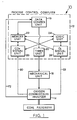
- an automatic calibration system or calibration control system 10 includes a known process control computer 12, such as a Bailey Controls Company Model Network 90, and a known oxygen/combustibles analyser 14, such as a Bailey Controls Company Model OL230 gas analyser. All operations and calculations performed by the computer 12 use known hardware/firmward algorithms. These algorithms are called function block units or function blocks because each algorithm performs a specific function.
- the hardware/firmware used by the function blocks includes combinations of microprocessors with internal, unchangeable operation commands to perform the desired function and will be referred to as units.
- the system 10 includes a data control unit 16 which energises a mechanical unit 18, by way of a timer unit 20, allowing a manual input of data to be microprocessor memory unit 22.
- the mechanical unit 18 allows calibration gases to be introduced into the analyser 14.
- the memory unit 22 provides storage for and access to all necessary values used by the entire system 10.
- the timer unit 20 is an internal digital clock circuit which controls all timing functions needed by the system 10.
- a logic unit 24 receives inputs from the memory unit 22 and alerts an operator if the inputs go beyond preset limits for zero and maximum scale (hereafter referred to as span) and performs calculations needed by a combustibles (hereafter referred to as CO e ) signal unit 26 and an oxygen (hereafter referred to as 02) signal unit 28.
- the signal units 26 and 28 respectively perform the actual calibration on a CO e indicating signal 30 and an 02 indicating signal 32, originating from the oxygen/combustibles analyser 14.
- the data control unit 16 has a manual data input station 34.
- the manual data input station 34 may be a known computerised data input keyboard or any other known manual data input apparatus.
- the manual data input station 34 allows an operator to selectively set the control unit 16 in an automatic mode 36, or to start a calibration sequence manually through a manual start button 38, to preset optimum zero and span values for CO e (40, 44) and 02 (42, 48), respectively, and to preset alarm limits 50 for the aforementioned optimum zero and span values.
- the preset values 40, 42, 44, 48, 50 may be tuned or adjusted by the operator at any time through the manual data input station 34.
- control unit 16 will be set in the automatic mode 36.
- the analyser 14 When in the automatic mode 36, the analyser 14 will be calibrated on a twenty-four hour interval 52. The interval will be maintained by the timer unit 20.
- the timer unit 20 provides that a calibration sequence will be peformed on the analyser 14 every day to ensure the accuracy of the oxygen and combustibles signals 30, 32 originating from the analyser 14.
- the manual start button 38 may also initiate a calibration sequency and will override the timer unit 20 to enable a calibration sequence to be performed at any time desired by the operator.
- an energise signal 54 is sent to the mechanical unit 18 along a line 56 from the process control computer 12.
- the mechanical unit 18 is physically attached by any known method to the analyser 14.
- the mechanical unit 18 begins the calibration sequence by performing a cleaning operation 58 on the analyser 14.
- the cleaning operation 58 is called a "puffback". In this operation, the mechanical unit 18 forces air back through the analyser 14 to clean the analyser 14.
- the cleaning operation 58 is controlled by the timer unit 20 to continue for a period of ten seconds.
- known solenoid valves 60 and 62 were energised to open by a control signal 64 allowing a zero calibration gas 66 to flow through a flowmeter 68 into the analyser 14.
- the gas 66 flows through the analyser 14 for a seven minute interval 70 as controlled by the timer unit 20.
- the timer unit 20 sends a control signal 67 to deenergise the valve 60 when the seven minute interval 70 is over.
- the gas 66, used for zero calibration usually consists of 1.0% 02 and 0 ppm CO e .
- a third solenoid valve 82 is energised by a control signal 84 originating from the timer unit 20, allowing a span gas 86 to flow through the flowmeter 68 to the analyser 14.
- the span gas 86 usually contains 20.9% 02 and 250 ppm CO e .
- the span gas 86 flows through the analyser 14 for a five minute interval 88.
- the timer unit 20 sends a control signal 90 to deenergise the valves 68 and 82.
- span values for CO e and 02 as sensed by the analyser 14 are sent to the computer 12 along the line 72.
- one minute moving averages of span values 92, 94 ( Figure 3) for CO e (92) and 02 (94) as sensed by the analyser 14 are calculated by the averaging function block unit 78 of the computer 12.
- the averages 92 and 94 are then sent to the memory unit 22 of the computer 12 along the line 80.
- the analyser 14 then returns to analysing a sample gas 96 from a coal pulveriser 98 and sending the signals indicative of CO e and 02 content, 30 and 32 respectively, to the CO e signal unit 26 and the 02 signal unit 28, respectively.
- the logic unit 24 accesses them.
- the logic unit 24 first compares the values 74, 76, 92, 94 to the preset alarm limits 50 in a compare function block unit 100. If any of the zero or span values 74, 76, 92, 94 for CO e and 02 are above their respective alarm limits 50, an alarm 102 will alert the operator to an inferior calibration condition and he will take steps necessary to correct it, including but not limited to a manual adjustment of the analyser. These instances are rare due to daily calibration and the daily cleaning opeation 58.
- the logic unit 24 then performs a calculation using the values 74, 76, 92, 94; the preset optimum zero values for CO e and 02, 40 and 42 respectively; and the preset span values for CO e and 02, 44 and 48 respectively.
- the preset values 40, 42, 44, 48 are accessed from the memory unit 22.
- the calculations are performed in difference function block units 104 and 106 and a dividing function block unit 108.
- the logic unit 24 sends calculated drift adjustments DaCO e 110 and Da02 112 to the CO e signal unit 26 and the 02 signal unit 28, respectively.
- the drift adjustments DaCO e 110 and Da02 112 are drift adjustments to be applied to the CO e and 02 sample signals 30 and 32, respectively.
- the drift adjustments 110 and 112 minimise the drift of the zero values 74, 76 and span values 92, 94 from their preset values 40, 42 and 44, 48, respectively.
- the calculation to arrive at the calibrated 02 output 114 is achieved by proportional function block units 116 and 118, a summation function block unit 120, and a difference function block unit 122.
- the output 114 is continuously monitored in a compare function block unit 124 to ensure that the coal pulveriser 98 being monitored does not go into a potentially dangerous situation.
- the output 114 goes above its preset alarm value 50, the operator is alerted of the dangerous situation by an alarm 126 and can take necessary steps to stabilise the coal pulveriser 98.
- the output 114 is sent to a known chart recorder 128 and also may be displayed on a known cathode ray tube monitor 130.
- the 02 signal unit 28 creates a calibration line graph 132, depicted in Figure 5, through its calculation.
- the Da02 value 112 is actually a proportion of error between the preset optimum scale and the scale the analyser 14 is outputting.
- the Da02 value 112 is then multiplied by the analyser 02 output 32 to arrive at the calibrated 02 output 114 with an offset added in for the preset zero value 42.
- the calibration graph 132 depicts the calibrated output 114, equal to 17.625% 02 content, for the given uncalibrated analyser output 32, equal to 19% 02. This calculation is performed continuously on the uncalibrated output 32 to give the continuous calibrated 02 signal 114.
- the CO e signal unit 26 which may be embodied as shown in Figure 6, operates in the same fashion as the 02 signal unit 28.
- the CO e signal unit 26 uses the same calculation used in the 02 signal unit 28, but performs this calculation using the CO e values 30, 74, 110. This calculation has no zero offset added in, however, because the preset zero value 28 is always zero. This calculation is performed in a difference function block unit 134 and a proportional function block unit 136.
- the CO e signal unit also uses a compare function block unit 138 to monitor a calibrated CO e signal 140 and alert the operator to a dangerous condition by an alarm 142.
- the calibrated CO e signal 140 may also be displayed on the cathode ray tube monitor 130 or the recorder 128.
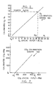
- a CO e calibration graph 144 is shown in Figure 7.
Landscapes
- Chemical & Material Sciences (AREA)
- Life Sciences & Earth Sciences (AREA)
- Health & Medical Sciences (AREA)
- Pathology (AREA)
- Immunology (AREA)
- Physics & Mathematics (AREA)
- Analytical Chemistry (AREA)
- Biochemistry (AREA)
- General Health & Medical Sciences (AREA)
- General Physics & Mathematics (AREA)
- Engineering & Computer Science (AREA)
- Combustion & Propulsion (AREA)
- Molecular Biology (AREA)
- Electrochemistry (AREA)
- Chemical Kinetics & Catalysis (AREA)
- Food Science & Technology (AREA)
- Medicinal Chemistry (AREA)
- Sampling And Sample Adjustment (AREA)
- Investigating Or Analyzing Non-Biological Materials By The Use Of Chemical Means (AREA)
- Regulation And Control Of Combustion (AREA)
- Testing Or Calibration Of Command Recording Devices (AREA)
- Investigating Or Analyzing Materials By The Use Of Electric Means (AREA)
- Incineration Of Waste (AREA)
- Other Investigation Or Analysis Of Materials By Electrical Means (AREA)
Abstract
Description
- This invention relates to the calibration of combined oxygen and combustibles analysers.
- Many known volatile atmosphere processes, such as those carried out in boiler furnaces and coal pulverisers, require constant monitoring to detect potentially flammable or explosive conditions and alert an operator to such conditions.
- Presently, several systems are being used to monitor potentially dangerous coal pulveriser atmospheres. Thermocouples and infra-red gas analysers are two systems used to monitor pulverisers. A shield is needed to protect these systems from the corrosive coal particles in the coal pulveriser. The shield reduces heat conduction to the thermocouple system, thereby reducing response time. Infra-red gas analysers need to condition the sample gas, also decreasing response time and sensitivity.
- A more reliable method used to monitor volatile atmospheres in coal pulverisers is to provide signals indicative of either oxygen, CO, or both. A certain quantity of each of these elements in a volatile atmosphere becomes indicative of the presence of a hazardous condition. Combination oxygen/combustibles analysers such as the Model OL230 supplied by Bailey Controls Company, a division of The Babcock & Wilcox Company, are used to provide such signals or combinations of them.
- These analysers must be calibrated frequently to make sure that they are providing an accurate measurement of the aforementioned elements in the volatile atmosphere. Presently, the calibration procedures for such analysers are not automated with the entire analyser control system.
- The present method for calibrating these analysers is manual. An operator manually introduces a test gas into the analyser, maintaining the air pressure as if the analyser was in operation. While maintaining the test gas pressure, calibration potentiometers are manually adjusted and test voltage outputs are monitored by hand-held voltmeters until desired calibrated outputs are attained.
- A known method of calibrating a combustibles signal consists of introducing a test gas into the analyser and maintaining the sample air pressure as in the manual calibration of the oxygen signal. Zero and span (maximum scale value) values from the test gas are adjusted by an operator. The incoming sample signal is then calibrated according to these adjusted values.
- The known calibration systems for combination oxygen/combustibles analysers are also manual. This inhibits the calibration of a plurality of analysers by one operator. The oxygen calibration operation requires at least fifteen minutes of operator time. This manual operation introduces the possibility of operator error and does not allow for repeatability of zero and span values. Further, the calibration of both combustibles and oxygen signals is not coordinated and thus hinders a plurality of analysers from being calibrated concurrently.
- Since the oxygen signal can drift significantly out of calibration before an operator becomes aware of the need for recalibration, a significant error with the oxygen signal is generated by the drift before it is detected and corrected.
- According to a first aspect of the invention there is provided an automatic calibration system for a combined oxygen and combustibles analyser, the system comprising:
an analyser for sensing a level of oxygen and a level of combustibles in a volatile atmosphere and producing a first signal indicative of the oxygen level and a second signal indicating of the combustibles level in the volatile atmosphere;
means for introducing calibration test gases into the analyser; and
means for concurrently calibrating the signals indicative of the oxygen and combustibles levels from the analyser. - According to a second aspect of the invention there is provided a method of automatically calibrating a combined oxygen and combustibles analyser, the method comprising the steps of:
providing predetermined time sequenced control signals;
purging the analyser by backflushing atmospheric air through the analyser for a predetermined period in response to the control signals;
establishing a signal indicating of the end of the purge;
introducing a zero test gas into the analyser in response to the signal indicative of the end of the purge and providing a signal indicative of the end of the zero test gas introduction;
introducing a maximum scale value gas to the analyser in response to the signal indicative of the end of the zero test gas introduction and providing a signal indicative of the end of the maximum scale value gas introduction; and
adjusting an output of the analyser to read zero and maximum scale upon provision of the signal indicative of the end of the maximum scale value gas introduction. - According to a third aspect of the invention there is provided an automatic control system for monitoring a hostile environment, the system comprising:
means for connecting the system to the environment;
means for presetting limit values;
means for analysing a level of combustibles and oxygen in the environment and providing signals indicating of the levels;
means for periodically calibrating the signals; and
means for alerting an operator whenever the calibrated signals are above the limit values. - A preferred embodiment of the present invention described hereinbelow overcomes or at least alleviates the problems associated with the non-automated control systems for oxygen/combustibles sensors by providing an improved safety monitoring system for oxygen and combustibles analysers using automatic calibration. The preferred system coordinates an automatic periodic calibration system with a signal sensing and safety alarm system to provide an entire monitoring/alarm/calibration system for oxygen and combustibles analysers. The system calibrates both the oxygen and combustibles signals in a fully automated fashion. A calibration procedure is initiated automatically on a predetermined interval such as every twenty-four hours. The calibration is performed concurrently on the oxygen signal and the combustible signal. Further, an alarm function is set into operation whenever calibrated zero and span values go beyond a preset limit. The preferred system then ensures than an accurate, hands-off calibration will be periodically performed. The preferred system is an accurate and reliable automatic calibration system which periodically calibrates the oxygen signal of the oxygen/combustibles analyser and coordinates it into a total control system for monitor/alarm/calibration of an entire safety monitoring unit. Further, the preferred system automatically adjusts both the span and zero values of both the oxygen and combustibles signals to minimise the effect of drift on the current analyser signal.
- The invention will now be further described, by way of illustrative and non-limiting example, with reference to the accompanying drawings, in which:
- Figure 1 is a schematic drawing of an automated calibration control system for oxygen and combustibles analysers according to a preferred embodiment of the present invention;
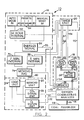
- Figure 2 is a schematic view of control logic for a data control unit and a mechanical unit shown in Figure 1;
- Figure 3 is a logic diagram for a logic unit shown in Figure 1;
- Figure 4 is a logic diagram for an oxygen signal unit shown in Figure 1;
- Figure 5 is an oxygen calibration graph used by the oxygen signal unit of Figure 4;
- Figure 6 is a logic diagram for a combustibles (COe) signal unit shown in Figure 1; and
- Figure 7 is a combustibles calibration graph used by the combustibles signal unit of Figure 6.
- Referring now to the drawings generally, with particular reference to Figure 1, an automatic calibration system or
calibration control system 10 includes a knownprocess control computer 12, such as a Bailey Controls Company Model Network 90, and a known oxygen/combustibles analyser 14, such as a Bailey Controls Company Model OL230 gas analyser. All operations and calculations performed by thecomputer 12 use known hardware/firmward algorithms. These algorithms are called function block units or function blocks because each algorithm performs a specific function. The hardware/firmware used by the function blocks includes combinations of microprocessors with internal, unchangeable operation commands to perform the desired function and will be referred to as units. - More particularly, the
system 10 includes adata control unit 16 which energises amechanical unit 18, by way of atimer unit 20, allowing a manual input of data to bemicroprocessor memory unit 22. Themechanical unit 18 allows calibration gases to be introduced into theanalyser 14. Thememory unit 22 provides storage for and access to all necessary values used by theentire system 10. Thetimer unit 20 is an internal digital clock circuit which controls all timing functions needed by thesystem 10. Alogic unit 24 receives inputs from thememory unit 22 and alerts an operator if the inputs go beyond preset limits for zero and maximum scale (hereafter referred to as span) and performs calculations needed by a combustibles (hereafter referred to as COe)signal unit 26 and an oxygen (hereafter referred to as 0₂)signal unit 28. Thesignal units signal 32, originating from the oxygen/combustibles analyser 14. - Referring now to Figure 2, the
data control unit 16 has a manualdata input station 34. The manualdata input station 34 may be a known computerised data input keyboard or any other known manual data input apparatus. The manualdata input station 34 allows an operator to selectively set thecontrol unit 16 in anautomatic mode 36, or to start a calibration sequence manually through amanual start button 38, to preset optimum zero and span values for COe (40, 44) and 0₂ (42, 48), respectively, and to preset alarm limits 50 for the aforementioned optimum zero and span values. The preset values 40, 42, 44, 48, 50 may be tuned or adjusted by the operator at any time through the manualdata input station 34. - Usually, the
control unit 16 will be set in theautomatic mode 36. When in theautomatic mode 36, theanalyser 14 will be calibrated on a twenty-fourhour interval 52. The interval will be maintained by thetimer unit 20. Thetimer unit 20 provides that a calibration sequence will be peformed on theanalyser 14 every day to ensure the accuracy of the oxygen and combustibles signals 30, 32 originating from theanalyser 14. Themanual start button 38 may also initiate a calibration sequency and will override thetimer unit 20 to enable a calibration sequence to be performed at any time desired by the operator. - When a calibration sequency is initiated either by actuating the
manual start button 38 or by thetimer unit 20, anenergise signal 54 is sent to themechanical unit 18 along aline 56 from theprocess control computer 12. Themechanical unit 18 is physically attached by any known method to theanalyser 14. - The
mechanical unit 18 begins the calibration sequence by performing acleaning operation 58 on theanalyser 14. The cleaningoperation 58 is called a "puffback". In this operation, themechanical unit 18 forces air back through theanalyser 14 to clean theanalyser 14. The cleaningoperation 58 is controlled by thetimer unit 20 to continue for a period of ten seconds. - When the
cleaning operation 58 is complete, knownsolenoid valves 60 and 62 were energised to open by acontrol signal 64 allowing a zero calibration gas 66 to flow through aflowmeter 68 into theanalyser 14. The gas 66 flows through theanalyser 14 for a sevenminute interval 70 as controlled by thetimer unit 20. Thetimer unit 20 sends a control signal 67 to deenergise the valve 60 when the sevenminute interval 70 is over. The gas 66, used for zero calibration, usually consists of 1.0% 0₂ and 0 ppm COe. - During the seven
minute interval 70, zero value signals for COe and 0₂ as sensed by theanalyser 14 are sent along aline 72 to thecomputer 12. When the sevenminute interval 70 is over, signals 74, 76 (Figure 3) indicative of a one minute moving average of zero values for both COe (74) and 0₂ (76) are calculated by an internal averagingfunction block unit 78 of thecomputer 12. The signals 74 and 76 are then sent to thememory unit 22 along aline 80. - At the end of the seven
minute interval 70, a third solenoid valve 82 is energised by acontrol signal 84 originating from thetimer unit 20, allowing a span gas 86 to flow through theflowmeter 68 to theanalyser 14. The span gas 86 usually contains 20.9% 0₂ and 250 ppm COe. The span gas 86 flows through theanalyser 14 for a fiveminute interval 88. At the end of the fiveminute interval 88 thetimer unit 20 sends acontrol signal 90 to deenergise thevalves 68 and 82. - During the five
minute interval 88, span values for COe and 0₂ as sensed by theanalyser 14 are sent to thecomputer 12 along theline 72. When the fiveminute interval 88 lapses, one minute moving averages of span values 92, 94 (Figure 3) for COe (92) and 0₂ (94) as sensed by theanalyser 14 are calculated by the averagingfunction block unit 78 of thecomputer 12. The averages 92 and 94 are then sent to thememory unit 22 of thecomputer 12 along theline 80. Theanalyser 14 then returns to analysing asample gas 96 from acoal pulveriser 98 and sending the signals indicative of COe and 0₂ content, 30 and 32 respectively, to the COe signal unit 26 and the 0₂signal unit 28, respectively. - Referring now to Figure 3, when the
data control unit 16 energises themechanical unit 18, it also energises thememory unit 22. This allows the COe and 0₂ zero values, 74 and 76 respectively, and the COe and 0₂ span values, 92 and 94 respectively, to be stored in thememory unit 22. - When the
memory unit 22 receives the zero values 74, 76 and the span values 92, 94, thelogic unit 24 accesses them. Thelogic unit 24 first compares the values 74, 76, 92, 94 to the preset alarm limits 50 in a comparefunction block unit 100. If any of the zero or span values 74, 76, 92, 94 for COe and 0₂ are above their respective alarm limits 50, an alarm 102 will alert the operator to an inferior calibration condition and he will take steps necessary to correct it, including but not limited to a manual adjustment of the analyser. These instances are rare due to daily calibration and thedaily cleaning opeation 58. - The
logic unit 24 then performs a calculation using the values 74, 76, 92, 94; the preset optimum zero values for COe and 0₂, 40 and 42 respectively; and the preset span values for COe and 0₂, 44 and 48 respectively. The preset values 40, 42, 44, 48 are accessed from thememory unit 22. The calculations are performed in differencefunction block units function block unit 108. The same calculation is performed on both the COe values 74, 92, 40, 44 and the 0₂values 
Ps = preset span value (COe-44 0₂-48);
Pz = preset zero value (COe-40 0₂-42);
As = actual span value (COe-92 0₂-94); and
Az = actual zero value (COe-74 0₂-76). - The
logic unit 24 sends calculateddrift adjustments DaCO e 110 andDa0₂ 112 to the COe signal unit 26 and the 0₂signal unit 28, respectively. Thedrift adjustments DaCO e 110 andDa0₂ 112 are drift adjustments to be applied to the COe and 0₂ sample signals 30 and 32, respectively. Thedrift adjustments preset values - The 0₂
signal unit 28, which may be embodied as shown in Figure 4, takes theDa0₂ calculation 112 from thelogic unit 24, the 0₂Pz value 42 and the 0₂Az value 76 from thememory unit 22, and the 0₂uncalibrated signal 32 from theanalyser 14, and performs the following calculation on them:
0₂Cal = Da(0₂s) + Pz - Da(Az)
where: 0₂Cal = calibrated 0₂output 114;
Da =drift adjustment 112;
O₂s = 0₂sample signal 32;
Pz = preset 0₂ zerovalue 42; and
Az = actual 0₂ zero value 76 - The calculation to arrive at the calibrated 0₂
output 114 is achieved by proportionalfunction block units function block unit 122. - The
output 114 is continuously monitored in a comparefunction block unit 124 to ensure that thecoal pulveriser 98 being monitored does not go into a potentially dangerous situation. When theoutput 114 goes above itspreset alarm value 50, the operator is alerted of the dangerous situation by analarm 126 and can take necessary steps to stabilise thecoal pulveriser 98. - The
output 114 is sent to a knownchart recorder 128 and also may be displayed on a known cathoderay tube monitor 130. - The 0₂
signal unit 28 creates acalibration line graph 132, depicted in Figure 5, through its calculation. TheDa0₂ value 112 is actually a proportion of error between the preset optimum scale and the scale theanalyser 14 is outputting. TheDa0₂ value 112 is then multiplied by the analyser 0₂output 32 to arrive at the calibrated 0₂output 114 with an offset added in for the preset zerovalue 42. Thecalibration graph 132 depicts the calibratedoutput 114, equal to 17.625% 0₂ content, for the givenuncalibrated analyser output 32, equal to 19% 0₂. This calculation is performed continuously on theuncalibrated output 32 to give the continuous calibrated 0₂signal 114. - The COe signal unit 26, which may be embodied as shown in Figure 6, operates in the same fashion as the 0₂
signal unit 28. The COe signal unit 26 uses the same calculation used in the 0₂signal unit 28, but performs this calculation using the COe values 30, 74, 110. This calculation has no zero offset added in, however, because the preset zerovalue 28 is always zero. This calculation is performed in a differencefunction block unit 134 and a proportionalfunction block unit 136. The COe signal unit also uses a comparefunction block unit 138 to monitor a calibrated COe signal 140 and alert the operator to a dangerous condition by analarm 142. The calibrated COe signal 140 may also be displayed on the cathoderay tube monitor 130 or therecorder 128. - A COe calibration graph 144 is shown in Figure 7.
Claims (17)
an analyser (14) for sensing a level of oxygen and a level of combustibles in a volatile atmosphere and producing a first signal indicative of the oxygen level and a second signal indicating of the combustibles level in the volatile atmosphere;
means (18) for introducing calibration test gases into the analyser (14); and
means (12) for concurrently calibrating the signals indicative of the oxygen and combustibles levels from the analyser (14).
providing (20) predetermined time sequenced control signals;
purging (58) the analyser (14) by backflushing atmospheric air through the analyser for a predetermined period in response to the control signals;
establishing a signal indicative of the end of the purge;
introducing a zero test gas (66) into the analyser (14) in response to the signal indicative of the end of the purge and providing a signal indicative of the end of the zero test gas introduction;
introducing a maximum scale value gas (86) into the analyser (14) in response to the signal indicative of the end of the zero test gas introduction and providing a signal indicative of the end of the maximum scale value gas introduction; and
adjusting (12) an output of the analyser (14) to read zero and maximum scale upon provision of the signal indicative of the end of the maximum scale value gas introduction.
means for connecting the system to the environment (98);
means (34) for presetting limit values (50);
means (14) for analysing a level of combustibles and oxygen in the environment (98) and providing signals indicative of the levels;
means (12, 18) for periodically calibrating the signals; and
means (100, 102) for alerting an operator whenever the calibrated signals are above the limit values (50).
Applications Claiming Priority (2)
| Application Number | Priority Date | Filing Date | Title |
|---|---|---|---|
| US854256 | 1986-04-21 | ||
| US06/854,256 US4852384A (en) | 1986-04-21 | 1986-04-21 | Automatic calibration and control system for a combined oxygen and combustibles analyzer |
Publications (3)
| Publication Number | Publication Date |
|---|---|
| EP0242946A2 true EP0242946A2 (en) | 1987-10-28 |
| EP0242946A3 EP0242946A3 (en) | 1988-07-06 |
| EP0242946B1 EP0242946B1 (en) | 1995-04-05 |
Family
ID=25318165
Family Applications (1)
| Application Number | Title | Priority Date | Filing Date |
|---|---|---|---|
| EP87301222A Expired - Lifetime EP0242946B1 (en) | 1986-04-21 | 1987-02-12 | Calibration of combined oxygen and combustibles analyses |
Country Status (12)
| Country | Link |
|---|---|
| US (1) | US4852384A (en) |
| EP (1) | EP0242946B1 (en) |
| JP (1) | JPH0660864B2 (en) |
| KR (1) | KR960006369B1 (en) |
| AR (1) | AR244433A1 (en) |
| AU (1) | AU596163B2 (en) |
| BR (1) | BR8702199A (en) |
| CA (1) | CA1293622C (en) |
| DE (1) | DE3751212T2 (en) |
| ES (1) | ES2070818T3 (en) |
| IN (1) | IN166321B (en) |
| MX (1) | MX169183B (en) |
Cited By (3)
| Publication number | Priority date | Publication date | Assignee | Title |
|---|---|---|---|---|
| DE3819100A1 (en) * | 1988-06-04 | 1989-12-07 | Conducta Mess & Regeltech | DEVICE FOR AUTOMATIC CALIBRATING GAS SENSORS |
| WO1992007261A1 (en) * | 1990-10-11 | 1992-04-30 | Spacelabs, Inc. | Automatic internal calibration circuit and method |
| EP1820015A4 (en) * | 2004-12-07 | 2011-09-07 | Honeywell Int Inc | System and method of sensitivity adjustment for an electrochemical sensor |
Families Citing this family (28)
| Publication number | Priority date | Publication date | Assignee | Title |
|---|---|---|---|---|
| JPH02115741A (en) * | 1988-10-25 | 1990-04-27 | Kurita Water Ind Ltd | gas sensor device |
| US5009099A (en) * | 1989-05-09 | 1991-04-23 | Varian Associates, Inc. | Background correction method for use in gas chromatography |
| JP2541051B2 (en) * | 1991-09-27 | 1996-10-09 | 株式会社島津製作所 | Limiting current type oxygen concentration measuring device |
| US5305231A (en) * | 1992-02-13 | 1994-04-19 | Bacharach, Inc. | Multiple K factor, selectable gas detector |
| US5402665A (en) * | 1993-05-11 | 1995-04-04 | Hart; Russell F. | Monitoring gaseous oxygen concentration |
| US5804695A (en) * | 1993-11-02 | 1998-09-08 | Horiba Instruments Incorporated | Gas dividing method and apparatus |
| US5756360A (en) * | 1995-09-29 | 1998-05-26 | Horiba Instruments Inc. | Method and apparatus for providing diluted gas to exhaust emission analyzer |
| US5846831A (en) * | 1997-04-01 | 1998-12-08 | Horiba Instuments, Inc. | Methods and systems for controlling flow of a diluted sample and determining pollutants based on water content in engine exhaust emissions |
| US6279377B1 (en) * | 1998-11-16 | 2001-08-28 | Litton Systems, Inc. | Method and apparatus for monitoring oxygen concentration |
| FR2804044B1 (en) * | 2000-01-25 | 2002-03-29 | Air Liquide | PROCESS AND DEVICE FOR OPTIMIZING REACTIVE GAS MIXTURES |
| KR100460658B1 (en) * | 2000-06-29 | 2004-12-09 | 주식회사 포스코 | An apparatus for analysising and controlling oxygen concentration of a fine coke device |
| US6712604B2 (en) | 2001-06-15 | 2004-03-30 | Honeywell International Inc. | Cautious optimization strategy for emission reduction |
| US8197561B2 (en) | 2001-10-10 | 2012-06-12 | River Basin Energy, Inc. | Process for drying coal |
| US7695535B2 (en) * | 2001-10-10 | 2010-04-13 | River Basin Energy, Inc. | Process for in-situ passivation of partially-dried coal |
| US7537622B2 (en) * | 2001-10-10 | 2009-05-26 | Fmi Newcoal, Inc. | Process for drying coal |
| JP4591105B2 (en) * | 2004-05-31 | 2010-12-01 | 横河電機株式会社 | Calibration method |
| US7987613B2 (en) | 2004-10-12 | 2011-08-02 | Great River Energy | Control system for particulate material drying apparatus and process |
| US7275644B2 (en) | 2004-10-12 | 2007-10-02 | Great River Energy | Apparatus and method of separating and concentrating organic and/or non-organic material |
| US8523963B2 (en) | 2004-10-12 | 2013-09-03 | Great River Energy | Apparatus for heat treatment of particulate materials |
| US8579999B2 (en) | 2004-10-12 | 2013-11-12 | Great River Energy | Method of enhancing the quality of high-moisture materials using system heat sources |
| US8062410B2 (en) | 2004-10-12 | 2011-11-22 | Great River Energy | Apparatus and method of enhancing the quality of high-moisture materials and separating and concentrating organic and/or non-organic material contained therein |
| US8109759B2 (en) * | 2006-03-29 | 2012-02-07 | Fives North America Combustion, Inc. | Assured compliance mode of operating a combustion system |
| GB0700677D0 (en) * | 2007-01-12 | 2007-02-21 | Servomex Group Ltd | Probe |
| US8956426B2 (en) | 2010-04-20 | 2015-02-17 | River Basin Energy, Inc. | Method of drying biomass |
| US9057037B2 (en) | 2010-04-20 | 2015-06-16 | River Basin Energy, Inc. | Post torrefaction biomass pelletization |
| US9075029B2 (en) * | 2011-01-31 | 2015-07-07 | Scott Technologies, Inc. | System and method for automatically adjusting gas sensor settings and parameters |
| JP2014109448A (en) * | 2012-11-30 | 2014-06-12 | Riken Keiki Co Ltd | Output correction method of contact combustion type gas sensor, and gas detector |
| US10088157B2 (en) | 2015-02-24 | 2018-10-02 | General Electric Technology Gmbh | Multi-sensor probe for monitoring combustion in a conduit |
Family Cites Families (18)
| Publication number | Priority date | Publication date | Assignee | Title |
|---|---|---|---|---|
| US3070988A (en) * | 1957-10-15 | 1963-01-01 | Standard Oil Co | Oxygen analyzer-standardizer |
| FR1375183A (en) * | 1963-08-28 | 1964-10-16 | Siderurgie Fse Inst Rech | Improvements to industrial process control methods by continuous analysis of a gas mixture of variable composition |
| US3838021A (en) * | 1973-07-18 | 1974-09-24 | United Nuclear Corp | Method and apparatus for in situ calibration of electrochemical sensors |
| US3924442A (en) * | 1973-10-09 | 1975-12-09 | Kvb Equipment Corp | Pollutant variation correcting system |
| JPS5414551Y2 (en) * | 1974-05-16 | 1979-06-15 | ||
| JPS5271585U (en) * | 1975-11-21 | 1977-05-28 | ||
| US4031747A (en) * | 1976-08-16 | 1977-06-28 | Beckman Instruments, Inc. | Misfire monitor for engine analysis having automatic rescaling |
| GB1529547A (en) * | 1976-08-16 | 1978-10-25 | Beckman Instruments Inc | Misfire monitor for engine analysis having automatic rescaling |
| JPS5459194A (en) * | 1977-10-20 | 1979-05-12 | Sankosha Co Ltd | Gas leakage alarm |
| JPS56112643A (en) * | 1980-02-12 | 1981-09-05 | Ngk Insulators Ltd | Simultaneous detection device for density of oxygen and combustible gas |
| US4279618A (en) * | 1980-06-03 | 1981-07-21 | Versar, Inc. | Method and apparatus for analysis of total atmospheric sulfuric acid content |
| DE3030448A1 (en) * | 1980-08-12 | 1982-03-11 | Brown, Boveri & Cie Ag, 6800 Mannheim | Temp. independent oxygen content determn. esp. for combustion gases - by using quotient of readings for known and unknown gas compositions |
| US4445359A (en) * | 1981-08-07 | 1984-05-01 | Measurex Corporation | System and process for calibrating a combustion gas analyzer |
| US4476706A (en) * | 1982-01-18 | 1984-10-16 | Delphian Partners | Remote calibration system |
| EP0089630A3 (en) * | 1982-03-19 | 1984-12-19 | Hitachi, Ltd. | Device for measuring oxygen concentration in exhaust gas |
| JPS5992337A (en) * | 1982-11-18 | 1984-05-28 | Mitaka Kogyo Kk | Gas analyzer |
| US4555930A (en) * | 1984-02-14 | 1985-12-03 | Control Instruments Corp. | Digital gas sensing system |
| US4578986A (en) * | 1984-07-06 | 1986-04-01 | Champion International Corporation | Gas analyzer for dry/dusty kilns |
-
1986
- 1986-04-21 US US06/854,256 patent/US4852384A/en not_active Expired - Lifetime
- 1986-11-14 IN IN825/CAL/86A patent/IN166321B/en unknown
- 1986-11-27 AR AR86306014A patent/AR244433A1/en active
- 1986-12-12 KR KR1019860010608A patent/KR960006369B1/en not_active Expired - Fee Related
-
1987
- 1987-01-28 CA CA000528428A patent/CA1293622C/en not_active Expired - Fee Related
- 1987-02-12 DE DE3751212T patent/DE3751212T2/en not_active Expired - Fee Related
- 1987-02-12 ES ES87301222T patent/ES2070818T3/en not_active Expired - Lifetime
- 1987-02-12 EP EP87301222A patent/EP0242946B1/en not_active Expired - Lifetime
- 1987-04-03 AU AU71065/87A patent/AU596163B2/en not_active Ceased
- 1987-04-21 JP JP62096382A patent/JPH0660864B2/en not_active Expired - Lifetime
- 1987-04-21 MX MX006113A patent/MX169183B/en unknown
- 1987-04-21 BR BR8702199A patent/BR8702199A/en unknown
Cited By (4)
| Publication number | Priority date | Publication date | Assignee | Title |
|---|---|---|---|---|
| DE3819100A1 (en) * | 1988-06-04 | 1989-12-07 | Conducta Mess & Regeltech | DEVICE FOR AUTOMATIC CALIBRATING GAS SENSORS |
| EP0345563A3 (en) * | 1988-06-04 | 1990-08-08 | Endress + Hauser Conducta Gesellschaft für Mess- und Regeltechnik mbH + Co. | Apparatus for the automatic calibration of gas sensors |
| WO1992007261A1 (en) * | 1990-10-11 | 1992-04-30 | Spacelabs, Inc. | Automatic internal calibration circuit and method |
| EP1820015A4 (en) * | 2004-12-07 | 2011-09-07 | Honeywell Int Inc | System and method of sensitivity adjustment for an electrochemical sensor |
Also Published As
| Publication number | Publication date |
|---|---|
| MX169183B (en) | 1993-06-24 |
| BR8702199A (en) | 1988-02-17 |
| ES2070818T3 (en) | 1995-06-16 |
| JPH0660864B2 (en) | 1994-08-10 |
| US4852384A (en) | 1989-08-01 |
| AU7106587A (en) | 1987-10-22 |
| CA1293622C (en) | 1991-12-31 |
| AU596163B2 (en) | 1990-04-26 |
| DE3751212D1 (en) | 1995-05-11 |
| AR244433A1 (en) | 1993-10-29 |
| DE3751212T2 (en) | 1995-08-10 |
| EP0242946B1 (en) | 1995-04-05 |
| KR870010402A (en) | 1987-11-30 |
| EP0242946A3 (en) | 1988-07-06 |
| JPS6324148A (en) | 1988-02-01 |
| KR960006369B1 (en) | 1996-05-15 |
| IN166321B (en) | 1990-04-14 |
Similar Documents
| Publication | Publication Date | Title |
|---|---|---|
| EP0242946A2 (en) | Calibration of combined oxygen and combustibles analyses | |
| US6910381B2 (en) | System and method of operation of an embedded system for a digital capacitance diaphragm gauge | |
| JP3698444B2 (en) | Method and apparatus for detecting and identifying defect sensors in a process | |
| EP0310233B1 (en) | Combustion control systems | |
| WO2002054086A1 (en) | Method of compensating for drift in gas sensing equipment | |
| EP0580110B1 (en) | Smoke detecting apparatus for fire alarm | |
| US4376026A (en) | Oxygen concentration measurement and control | |
| GB2183342A (en) | Displaying corrected transducer readings | |
| US5007283A (en) | Method and device for processing measured values | |
| US5966676A (en) | Calibration-inability warning method in analyzing apparatus | |
| US5315376A (en) | Method and apparatus for correcting concentration | |
| US4569223A (en) | Method of and apparatus for multiple detector measurement of an environmental parameter | |
| EP0072105B1 (en) | Assessment of life of duct | |
| JPH04291141A (en) | Flammable gas detection device and its compensation operation method | |
| EP0672245B1 (en) | Humidity measuring instrument | |
| JPH06281477A (en) | Continuous analyzer | |
| JP3047947B2 (en) | Plant monitoring equipment | |
| HU216237B (en) | Method and apparatus for controlling the production of carbon black in a carbon black reactor | |
| US6267928B1 (en) | Capnometer | |
| JPH068683Y2 (en) | Grain silo management device due to temperature difference | |
| JPH05249074A (en) | Carbon dioxide concentration detection apparatus | |
| JPH05159074A (en) | Automatic calibration device | |
| JPH0470676B2 (en) | ||
| JP2732270B2 (en) | Temperature control method | |
| JPH0627077A (en) | Cell-life estimating system |
Legal Events
| Date | Code | Title | Description |
|---|---|---|---|
| PUAI | Public reference made under article 153(3) epc to a published international application that has entered the european phase |
Free format text: ORIGINAL CODE: 0009012 |
|
| AK | Designated contracting states |
Kind code of ref document: A2 Designated state(s): DE ES FR GB IT |
|
| PUAL | Search report despatched |
Free format text: ORIGINAL CODE: 0009013 |
|
| RHK1 | Main classification (correction) |
Ipc: G01N 27/56 |
|
| AK | Designated contracting states |
Kind code of ref document: A3 Designated state(s): DE ES FR GB IT |
|
| 17P | Request for examination filed |
Effective date: 19881115 |
|
| RAP1 | Party data changed (applicant data changed or rights of an application transferred) |
Owner name: INTERNATIONAL CONTROL AUTOMATION FINANCE S.A. |
|
| 17Q | First examination report despatched |
Effective date: 19910130 |
|
| GRAA | (expected) grant |
Free format text: ORIGINAL CODE: 0009210 |
|
| AK | Designated contracting states |
Kind code of ref document: B1 Designated state(s): DE ES FR GB IT |
|
| REF | Corresponds to: |
Ref document number: 3751212 Country of ref document: DE Date of ref document: 19950511 |
|
| ET | Fr: translation filed | ||
| ITF | It: translation for a ep patent filed | ||
| REG | Reference to a national code |
Ref country code: ES Ref legal event code: FG2A Ref document number: 2070818 Country of ref document: ES Kind code of ref document: T3 |
|
| PLBE | No opposition filed within time limit |
Free format text: ORIGINAL CODE: 0009261 |
|
| STAA | Information on the status of an ep patent application or granted ep patent |
Free format text: STATUS: NO OPPOSITION FILED WITHIN TIME LIMIT |
|
| 26N | No opposition filed | ||
| PGFP | Annual fee paid to national office [announced via postgrant information from national office to epo] |
Ref country code: GB Payment date: 20010112 Year of fee payment: 15 |
|
| PGFP | Annual fee paid to national office [announced via postgrant information from national office to epo] |
Ref country code: FR Payment date: 20010205 Year of fee payment: 15 Ref country code: DE Payment date: 20010205 Year of fee payment: 15 |
|
| PGFP | Annual fee paid to national office [announced via postgrant information from national office to epo] |
Ref country code: ES Payment date: 20010220 Year of fee payment: 15 |
|
| REG | Reference to a national code |
Ref country code: GB Ref legal event code: IF02 |
|
| PG25 | Lapsed in a contracting state [announced via postgrant information from national office to epo] |
Ref country code: GB Free format text: LAPSE BECAUSE OF NON-PAYMENT OF DUE FEES Effective date: 20020212 |
|
| PG25 | Lapsed in a contracting state [announced via postgrant information from national office to epo] |
Ref country code: ES Free format text: LAPSE BECAUSE OF NON-PAYMENT OF DUE FEES Effective date: 20020213 |
|
| PG25 | Lapsed in a contracting state [announced via postgrant information from national office to epo] |
Ref country code: DE Free format text: LAPSE BECAUSE OF NON-PAYMENT OF DUE FEES Effective date: 20020903 |
|
| GBPC | Gb: european patent ceased through non-payment of renewal fee |
Effective date: 20020212 |
|
| PG25 | Lapsed in a contracting state [announced via postgrant information from national office to epo] |
Ref country code: FR Free format text: LAPSE BECAUSE OF NON-PAYMENT OF DUE FEES Effective date: 20021031 |
|
| REG | Reference to a national code |
Ref country code: FR Ref legal event code: ST |
|
| REG | Reference to a national code |
Ref country code: ES Ref legal event code: FD2A Effective date: 20030922 |
|
| PG25 | Lapsed in a contracting state [announced via postgrant information from national office to epo] |
Ref country code: IT Free format text: LAPSE BECAUSE OF NON-PAYMENT OF DUE FEES;WARNING: LAPSES OF ITALIAN PATENTS WITH EFFECTIVE DATE BEFORE 2007 MAY HAVE OCCURRED AT ANY TIME BEFORE 2007. THE CORRECT EFFECTIVE DATE MAY BE DIFFERENT FROM THE ONE RECORDED. Effective date: 20050212 |