EP0310233B1 - Combustion control systems - Google Patents
Combustion control systems Download PDFInfo
- Publication number
- EP0310233B1 EP0310233B1 EP88307500A EP88307500A EP0310233B1 EP 0310233 B1 EP0310233 B1 EP 0310233B1 EP 88307500 A EP88307500 A EP 88307500A EP 88307500 A EP88307500 A EP 88307500A EP 0310233 B1 EP0310233 B1 EP 0310233B1
- Authority
- EP
- European Patent Office
- Prior art keywords
- alarm
- sensor
- parameters
- display
- prioritisation
- Prior art date
- Legal status (The legal status is an assumption and is not a legal conclusion. Google has not performed a legal analysis and makes no representation as to the accuracy of the status listed.)
- Expired - Lifetime
Links
- 238000002485 combustion reaction Methods 0.000 title claims description 36
- 238000000034 method Methods 0.000 claims description 67
- 238000012913 prioritisation Methods 0.000 claims description 29
- 238000012544 monitoring process Methods 0.000 claims description 12
- 230000006870 function Effects 0.000 claims description 10
- 238000012545 processing Methods 0.000 claims description 10
- 238000010276 construction Methods 0.000 claims description 3
- 230000004044 response Effects 0.000 claims description 3
- QVGXLLKOCUKJST-UHFFFAOYSA-N atomic oxygen Chemical compound [O] QVGXLLKOCUKJST-UHFFFAOYSA-N 0.000 description 22
- 229910052760 oxygen Inorganic materials 0.000 description 22
- 239000001301 oxygen Substances 0.000 description 22
- 230000000881 depressing effect Effects 0.000 description 15
- 239000000446 fuel Substances 0.000 description 11
- 239000007789 gas Substances 0.000 description 11
- 239000004020 conductor Substances 0.000 description 8
- 239000000523 sample Substances 0.000 description 8
- 238000003745 diagnosis Methods 0.000 description 6
- 238000010586 diagram Methods 0.000 description 5
- 239000012528 membrane Substances 0.000 description 5
- 230000002159 abnormal effect Effects 0.000 description 4
- 238000001514 detection method Methods 0.000 description 4
- 238000010438 heat treatment Methods 0.000 description 4
- 238000004886 process control Methods 0.000 description 4
- UGFAIRIUMAVXCW-UHFFFAOYSA-N Carbon monoxide Chemical compound [O+]#[C-] UGFAIRIUMAVXCW-UHFFFAOYSA-N 0.000 description 3
- 230000001276 controlling effect Effects 0.000 description 3
- 239000003546 flue gas Substances 0.000 description 3
- 238000004458 analytical method Methods 0.000 description 2
- 238000009529 body temperature measurement Methods 0.000 description 2
- 239000000567 combustion gas Substances 0.000 description 2
- 230000003750 conditioning effect Effects 0.000 description 2
- 238000012937 correction Methods 0.000 description 2
- 230000001419 dependent effect Effects 0.000 description 2
- 230000000994 depressogenic effect Effects 0.000 description 2
- 238000012423 maintenance Methods 0.000 description 2
- 238000005259 measurement Methods 0.000 description 2
- 238000005070 sampling Methods 0.000 description 2
- 238000013024 troubleshooting Methods 0.000 description 2
- OKTJSMMVPCPJKN-UHFFFAOYSA-N Carbon Chemical compound [C] OKTJSMMVPCPJKN-UHFFFAOYSA-N 0.000 description 1
- XAGFODPZIPBFFR-UHFFFAOYSA-N aluminium Chemical compound [Al] XAGFODPZIPBFFR-UHFFFAOYSA-N 0.000 description 1
- 229910052782 aluminium Inorganic materials 0.000 description 1
- 239000004411 aluminium Substances 0.000 description 1
- 229910002091 carbon monoxide Inorganic materials 0.000 description 1
- 239000011248 coating agent Substances 0.000 description 1
- 238000000576 coating method Methods 0.000 description 1
- 238000013480 data collection Methods 0.000 description 1
- 230000007423 decrease Effects 0.000 description 1
- 238000002405 diagnostic procedure Methods 0.000 description 1
- 238000005516 engineering process Methods 0.000 description 1
- 238000004868 gas analysis Methods 0.000 description 1
- 229910002804 graphite Inorganic materials 0.000 description 1
- 239000010439 graphite Substances 0.000 description 1
- 238000005286 illumination Methods 0.000 description 1
- 239000004973 liquid crystal related substance Substances 0.000 description 1
- 230000007257 malfunction Effects 0.000 description 1
- 239000000463 material Substances 0.000 description 1
- 238000011022 operating instruction Methods 0.000 description 1
- 230000000737 periodic effect Effects 0.000 description 1
- 238000010926 purge Methods 0.000 description 1
- 230000001105 regulatory effect Effects 0.000 description 1
- 238000012552 review Methods 0.000 description 1
- 238000012163 sequencing technique Methods 0.000 description 1
- 230000011664 signaling Effects 0.000 description 1
- 230000000007 visual effect Effects 0.000 description 1
Images


Classifications
-
- H—ELECTRICITY
- H05—ELECTRIC TECHNIQUES NOT OTHERWISE PROVIDED FOR
- H05K—PRINTED CIRCUITS; CASINGS OR CONSTRUCTIONAL DETAILS OF ELECTRIC APPARATUS; MANUFACTURE OF ASSEMBLAGES OF ELECTRICAL COMPONENTS
- H05K7/00—Constructional details common to different types of electric apparatus
- H05K7/14—Mounting supporting structure in casing or on frame or rack
- H05K7/1462—Mounting supporting structure in casing or on frame or rack for programmable logic controllers [PLC] for automation or industrial process control
- H05K7/1484—Electrical diagrams relating to constructional features, e.g. signal routing within PLC; Provisions for disaster recovery, e.g. redundant systems
-
- F—MECHANICAL ENGINEERING; LIGHTING; HEATING; WEAPONS; BLASTING
- F23—COMBUSTION APPARATUS; COMBUSTION PROCESSES
- F23N—REGULATING OR CONTROLLING COMBUSTION
- F23N5/00—Systems for controlling combustion
- F23N5/24—Preventing development of abnormal or undesired conditions, i.e. safety arrangements
- F23N5/242—Preventing development of abnormal or undesired conditions, i.e. safety arrangements using electronic means
-
- F—MECHANICAL ENGINEERING; LIGHTING; HEATING; WEAPONS; BLASTING
- F23—COMBUSTION APPARATUS; COMBUSTION PROCESSES
- F23N—REGULATING OR CONTROLLING COMBUSTION
- F23N5/00—Systems for controlling combustion
- F23N5/26—Details
-
- F—MECHANICAL ENGINEERING; LIGHTING; HEATING; WEAPONS; BLASTING
- F23—COMBUSTION APPARATUS; COMBUSTION PROCESSES
- F23N—REGULATING OR CONTROLLING COMBUSTION
- F23N1/00—Regulating fuel supply
- F23N1/02—Regulating fuel supply conjointly with air supply
-
- F—MECHANICAL ENGINEERING; LIGHTING; HEATING; WEAPONS; BLASTING
- F23—COMBUSTION APPARATUS; COMBUSTION PROCESSES
- F23N—REGULATING OR CONTROLLING COMBUSTION
- F23N2223/00—Signal processing; Details thereof
- F23N2223/04—Memory
-
- F—MECHANICAL ENGINEERING; LIGHTING; HEATING; WEAPONS; BLASTING
- F23—COMBUSTION APPARATUS; COMBUSTION PROCESSES
- F23N—REGULATING OR CONTROLLING COMBUSTION
- F23N2223/00—Signal processing; Details thereof
- F23N2223/08—Microprocessor; Microcomputer
-
- F—MECHANICAL ENGINEERING; LIGHTING; HEATING; WEAPONS; BLASTING
- F23—COMBUSTION APPARATUS; COMBUSTION PROCESSES
- F23N—REGULATING OR CONTROLLING COMBUSTION
- F23N2223/00—Signal processing; Details thereof
- F23N2223/38—Remote control
-
- F—MECHANICAL ENGINEERING; LIGHTING; HEATING; WEAPONS; BLASTING
- F23—COMBUSTION APPARATUS; COMBUSTION PROCESSES
- F23N—REGULATING OR CONTROLLING COMBUSTION
- F23N2231/00—Fail safe
- F23N2231/20—Warning devices
-
- F—MECHANICAL ENGINEERING; LIGHTING; HEATING; WEAPONS; BLASTING
- F23—COMBUSTION APPARATUS; COMBUSTION PROCESSES
- F23N—REGULATING OR CONTROLLING COMBUSTION
- F23N5/00—Systems for controlling combustion
- F23N5/003—Systems for controlling combustion using detectors sensitive to combustion gas properties
- F23N5/006—Systems for controlling combustion using detectors sensitive to combustion gas properties the detector being sensitive to oxygen
-
- G—PHYSICS
- G05—CONTROLLING; REGULATING
- G05B—CONTROL OR REGULATING SYSTEMS IN GENERAL; FUNCTIONAL ELEMENTS OF SUCH SYSTEMS; MONITORING OR TESTING ARRANGEMENTS FOR SUCH SYSTEMS OR ELEMENTS
- G05B2219/00—Program-control systems
- G05B2219/20—Pc systems
- G05B2219/24—Pc safety
- G05B2219/24063—Select signals as function of priority, importance for diagnostic
-
- G—PHYSICS
- G05—CONTROLLING; REGULATING
- G05B—CONTROL OR REGULATING SYSTEMS IN GENERAL; FUNCTIONAL ELEMENTS OF SUCH SYSTEMS; MONITORING OR TESTING ARRANGEMENTS FOR SUCH SYSTEMS OR ELEMENTS
- G05B2219/00—Program-control systems
- G05B2219/20—Pc systems
- G05B2219/24—Pc safety
- G05B2219/24103—Graphical display of proces as function of detected alarm signals
Definitions
- Oxygen and combustibles analysers are often used to analyse combustion gases in data collection and combustion control systems. These analysers are effective in improving product quality and combustion efficiency, as compared to systems without combustion gas analysis.
- a major drawback to these analysers, however, is that sampling, sensing, and heating systems that are required for their proper operation tend to be complex and prone to failure.
- the solenoid digital output routines 105 control gas flow to the analyser during a calibration cycle by operating the appropriate control valve to adjust zero setting, span and blowback.
- the operator interface status decoding routines 108 determine the display status conditions and initiate the proper action required by signals inputted from the keyboard interface. These routines also regulate data flow sent to the display interface 24.
- the sensor assembly 11 provides various signal inputs, including signals proportional to oxygen concentration, combustibles concentration, oxygen sensor block temperature, combustibles sensor block temperature, and a cold junction compensator used in conjunction with the thermocouples used for temperature measurement.
- the sensor assembly 11 also contains heaters which are used to heat the sensors and the sample gas to predetermined, constant temperatures.
- the signal inputs are then fed to electronic circuits of the process controller 12 and are fed through the multiplexer and signal conditioners 21 and the A/D converter 22. These signals are then manipulated by firmware resident in the microprocessor 23. The results of these manipulations are made available to the user via the operator interface unit 24. Much of this same information is made available to analog outputs and digital outputs. The analog outputs are used to provide a direct indication of measured parameters, whereas the digital outputs provide information on the status of a particular variable. Heater control circuitry is used to convert logic level signals from the microprocessor 23 to the power levels needed by the sensor heaters.
- Sensor zero and span alarms 132 for both the oxygen and combustible sensors 14, 15 are always displayed because the alarms are also not necessarily caused by other analyser fault conditions.
- the analyser power alarm 133 has priority over any further alarms. If a power switch (not shown) is turned off, neither the cold junction compensator 18 ( Figure 1) nor the sensor heaters ( Figure 1) have power. Thus, both a cold junction compensator alarm and a temperature alarm will occur as a direct result of turning off the power and are therefore redundant indications of a known condition.
- the cold junction compensator 18 ( Figure 1) is an integrated part of the temperature measurement of both the flange manifold and the combustible sensor block. If the cold junction compensator fails, these temperatures will be erroneous, the the sensor outputs will be invalid. Therefore, the cold junction compensator alarm 134 has priority over the remaining alarms because if the cold junction compensator reading is invalid, the other alarms will occur as a direct result of this condition, and are therefore redundant.
- the system constantly monitors analyser parameters and informs the control system of abnormal conditions.
- the control system can default immediately to a predetermined condition.
- the system automatically prioritises analyser alarms and displays only relevant alarms. These alarms are displayed in easy to understand English sentences.
- the digital outputs provide a remote indication of system status as well as an additional safety output. These outputs inform the operator of abnormal conditions. A more detailed explanation of these conditions is then available through the operator interface.
- the routine When the operator depresses the NEXT SCREEN key 37 in the alarm environment, the routine obtains the list of alarms, obtains the alarm being viewed and sets the pointer to the next valid alarm.
- the next valid alarm is the next alarm which can be displayed given the current alarm and the priority structure of the system. For example, with reference to Figure 4, if the flange manifold temperature is out of range, the next valid alarm is the CO block temperature alarm.
- the alarm acknowledge routine is executed. If there is an existing alarm, the pointer is initialised. Then, the pointer is incremented and, if there is another alarm, an alarm LED flash bit is set. If there are no more alarms, then the alarm acknowledged check routine is executed and, if an unacknowledged alarm is found, the alarm LED flash bit is set. Otherwise, if any alarm is found the pointer is set to the next valid alarm. Otherwise, the routine loops back to increment the pointer and search for any further alarms.
Landscapes
- Engineering & Computer Science (AREA)
- Chemical & Material Sciences (AREA)
- Combustion & Propulsion (AREA)
- Mechanical Engineering (AREA)
- General Engineering & Computer Science (AREA)
- Automation & Control Theory (AREA)
- Computer Networks & Wireless Communication (AREA)
- Microelectronics & Electronic Packaging (AREA)
- Investigating Or Analyzing Materials By The Use Of Electric Means (AREA)
- Testing And Monitoring For Control Systems (AREA)
- Feedback Control In General (AREA)
- Regulation And Control Of Combustion (AREA)
- Feeding And Controlling Fuel (AREA)
Description
- This invention relates to combustion control systems.
- Oxygen and combustibles analysers are often used to analyse combustion gases in data collection and combustion control systems. These analysers are effective in improving product quality and combustion efficiency, as compared to systems without combustion gas analysis. A major drawback to these analysers, however, is that sampling, sensing, and heating systems that are required for their proper operation tend to be complex and prone to failure.
- Current oxygen and combustibles analysers provide little in the way of diagnostics to aid in system maintenance. As a rule, signals proportional to the oxygen and combustibles concentration in the analysed gas are the only system outputs. Signals which represent an internal analyser condition are not provided as outputs. Correction factors based on the results of sensor calibration by automatic calibration systems are sometimes available. However, these correction factors are not easily accessible, and their meaning is not obvious to those without specialised knowledge.
- These factors cause difficulty in interfacing the analyser to a system controller. Because the basic operating conditions within the analyser are unknown, erroneous flue gas measurements resulting from analyser fault conditions may be used as control system inputs. Such erroneous inputs may result in inefficient and potentially unsafe conditions as the controller responds to them. A combustion control system using the output of a combustion analyser as an input could operate for significant periods of time based on false inputs. Thus, redundant measurements or complicated control systems were required. Thus, it would be desirable to have a combustion control system which monitors analyser parameters and responds to abnormal conditions to default immediately.
- German Patent Application Publication No DE-A-3 335 481 discloses a warning (alarm) display system according to the pre-characterising part of claim 1 of this application, the system (which may be associated with a control station such as an energy generation control room or - in particular - an aircraft cockpit) including: a sensor assembly having sensor means for providing output signals indicative of parameters; and controller means comprising input means for receiving said output signals provided by said sensor means, monitoring means for continuously monitoring said parameters and generating alarm signals, display means for displaying alarm conditions in response to said alarm signals, prioritisation means for automatically prioritising the display of said alarm conditions, and a memory.
- The display system of DE-A-3 335 481 functions in that the controller means (a data processor) evaluates the output signals from the sensors, in comparison with existing items of reference information, to ascertain whether information -and in particular a warning display - should be displayed on the display means, and reads appropriate information from the memory for presentation in a given region of the display means. The display means is in the form of a pair of lines for multi-place alphanumeric information display, each line being subdivided into separately actuable line portions. Thus, long or short items of information can be displayed. Prioritisation of display is effected in that the most current or important information is presented on the uppermost line or in a more detailed text. Later/lower priority occurrences may be stored so that the operator can output them later for review.
- DE-A-3 614 331 discloses a diagnostic system (for example for a nuclear power station) comprising input means for acquiring raw data relating to a deviant state, a memory for storing logic data for diagnosis of a deviant state, a processor for diagnosis of a deviant state on the basis of the logic data, another memory for storing the diagnosis results, a display means for displaying the diagnosis results, and a prioritisation means for outputting the diagnosis results in a priority sequence which, in the event of simultaneous diagnosis results, corresponds to the relative importance of the results.
- US Patent No US-A-3 988 730 discloses a system for monitoring and indicating parameter conditions within a system, in particular an automobile. Sensors provide output signals indicative of parameters. Each signal is compared with an individually programmed reference, and a corresponding indicator is activated if the signal exceeds its reference. Each parameter is prioritised such that if it exceeds its reference the system will sequentially sense only that parameter and all other parameters of a higher priority.
- According to the present invention there is provided a system including: a sensor assembly having sensor means for providing output signals indicative of parameters; and controller means comprising input means for receiving said output signals provided by said sensor means, monitoring means for continuously monitoring said parameters and generating alarm signals, display means for displaying alarm conditions in response to said alarm signals, prioritisation means for automatically prioritising the display of said alarm conditions, and a memory;
characterised in that:
said system is a combustion control system for controlling a combustion process;
said controller means is a process controller means operative to control said combustion process;
said sensor means is operative to provide said output signals indicative of at least one parameter of said combustion control process;
said controller means includes signal processing means responsive to said output signals provided by said sensor means to generate control outputs to maintain a desired operation of said combustion control process;
said monitoring means forms part of said signal processing means and is operative to continuously monitor parameters of the combustion control system including said at least one parameter of said combustion control process provided by said sensor means and to generate an alarm signal whenever any one of the monitored parameters deviates from a setpoint value;
said prioritisation means is operative automatically to prioritise said alarm signals to provide a display of select alarm conditions based on knowledge of internal operations of an analyser system which is a direct result of a construction of said analyser system; and
said combustion control system and said prioritisation means are operative to disregard suspect sensor readings through a program stored in said memory. - A preferred embodiment of the invention described in detail below provides: a more reliable combustion control system; a more reliable oxygen and combustibles analyser; an improved diagnostic system for combustion control systems; and a combustion control system which includes a combustion process sample analyser and which continuously monitors parameters of the analyser and detects predetermined abnormal conditions relating to operation of the analyser.
- By suppressing redundant alarms, trouble shooting is made easier because the operator is not required to recognise and ignore spurious information. Also, when an analyser alarm is detected, the system may automatically default the appropriate part of the control system to a known safe operating condition.
- The invention will now be further described, by way of illustrative and non-limiting example, with reference to the accompanying drawings, in which:
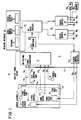
- Figure 1 is a block diagram of a combustion control system embodying the invention;
- Figure 1A is a plan view of an operator interface apparatus for the system shown in Figure 1;
- Figure 1B is a sectional view taken along lines 1B-1B in Figure 1A;
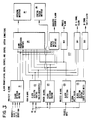
- Figure 2 is a block diagram illustrating control programs of the system shown in Figure 1;
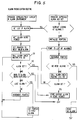
- Figure 3 is a block diagram illustrating alarm detection and prioritisation routines for the system;
- Figure 4 is a diagrammatic representation of alarm priority status for the system;
- Figure 5 is a process flow chart for the alarm prioritisation routine;
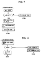
- Figure 6 is a process flow chart for an alarm acknowledge routine;
- Figure 7 is a process flow chart for an alarm check routine; and
- Figure 8 is a process flow chart for the alarm detection routine.
- A
combustion control system 10 in accordance with a preferred embodiment of the invention is illustrated in block diagram form in Figure 1. Thesystem 10 maintains an optimum gas combustion by sampling flue gases and controlling the settings of a gas (fuel) valve 10a and anair damper 10b as a function of process variables, including the percentages of oxygen and carbon monoxide in the flue gas, and system operating conditions. - The
combustion control system 10 includes a sensor assembly 11 and aprocess controller 12, including electronic circuits, which are interconnected by asystem cable assembly 13, includingconductors 13a to 13h. The sensor assembly 11, which is located near the process being controlled, includes anoxygen sensor 14, acombustibles sensors 15 and a sensor probe (not shown) which is located in a duct (not shown) for extracting a sample of products of a combustion process for analysis. The sample is divided between theoxygen sensor 14 and thecombustibles sensor 15 in a manner known in the art. The sensor assembly 11 includes an air powered aspirator (not shown) for drawing the sample from the process and across the twosensors sensors process controller 12 via theconductors interconnecting cable assembly 13. - In addition to analog signals representing outputs of the two
sensors process controller 12 monitoring signals indicative of parameters or conditions of the sensors and/or hardware associated therewith. The sensor assembly 11 includes atemperature sensor 16 providing an output indicative of the temperature of a flange manifold represented by a block (support member) 14a on which theoxygen sensor 14 is mounted, and atemperature sensor 17 providing an output indicative of the temperature of a mounting block represented by a block (support member) 15a on which thecombustibles sensor 15 is mounted. These parameter outputs are transmitted over theconductors process controller 12. Afurther sensor 18 provides a process input, such as ambient temperature or pressure, which is supplied to theprocess controller 12 via theconductor 13f. - In order to maintain the temperature of the sensors and sensor mountings at the required operating temperatures and above the dew point, the sensors are maintained at elevated operating temperatures by heating the support member 14a, 15a on which the sensors are mounted. To this end, the sensor assembly 11 includes a flange
manifold heating device 19 and a combustibles block heating device 19a, both of which receive control signals via theconductors 13g and 13h from theprocess controller 12. - A thermocouple 20 is used in controlling the process. A cold junction compensator, as it is called, is a thermally dependent current regulating device that accounts for the actual ambient temperature in the termination unit of the sensor assembly 11. This information is required for accuracy with any type of thermocouple used, and is transmitted over the
conductor 13e to theprocess controller 12. A single cold junction compensator is used to compensate both for theprocess variable sensor 18, which is embodied as a thermocouple, and the twoparameter sensors - The
process controller 12 includes multiplexing andsignal conditioning circuits 21, an analog-to-digital (A/D) converter (converter circuit) 22, amicroprocessor 23, an operator interface (interface unit) 24 andoutput circuits 25 including adigital output interface 26, ananalog output interface 27, andheater control circuits 28. - The multiplexing
circuits 21 receive the analog signals provided by the sensor assembly 11 and the process input and extend them one at a time to the A/D converter 22 which converts the signals to digital form for processing by themicroprocessor 23. Asuitable microprocessor 23 for this system is the Motorola Type 68MC11 which includes, in addition to a digital signal processor, read only memory, random access memory, a programmable memory, a serial input/output port, and a timer system. Themicroprocessor 23 monitors the analyser status and initiates changes, particularly changes in temperature, to maintain a desired status of the sensor assembly 11. Themicroprocessor 23 compares the sensor signal levels received from the sensor assembly 11 with setpoint values and, based upon user input parameters, makes changes in settings of process apparatus (not shown), such as air damper controls, fuel valves, etc., to maximise the efficiency of the combustion process being monitored. Themicroprocessor 23 also stores calibration information for maintaining the sensors in accurate and repeatable operating condition. - More specially, the analog signals applied to the
process controller 12 are sampled in a continuous, sequential manner by the multiplexing andsignal conditioning circuits 21 which filter and amplify the signals before applying the signals to the A/D converter 22. The analog signals are converted to digital form and applied to themicroprocessor 23 which operates under program control to receive and process the digital inputs provided thereto by the A/D converter 22 and to generate suitable control outputs which are applied via thedigital output interface 26 oranalog output interface 27 to control apparatus. Control routines and diagnostic routines of the system will be described in more detail hereinafter. - In addition to the analog signals converted to digital form by the input section of the electronics circuit of the
process controller 12 prior to processing by themicroprocessor 23, theprocess controller 12 receives further inputs via theoperator interface unit 24 which enables the operator to input data, setpoint values and control commands to the system. Theoperator interface unit 24 also provides for the operator a display of information provide by themicroprocessor 23, including alarm condition information, status information, etc. As will be shown, theprocess controller 12 automatically prioritises system alarms which are displayed and provides a display of only relevant alarms. In other words, if a signal becomes invalid because of another alarm conditions, alarms generated by that signal are not displayed to the operator. In addition, theoperator interface unit 24 includes a plurality of status indicators which provide visual indication to the operator of various conditions of the system including the presence of an unacknowledged alarm. - Referring to Figures 1 and 1A, the
operator interface unit 24 comprises amembrane keyboard 31, alphanumeric liquid crystal display (LCD) ordisplay unit 32, and a plurality ofstatus indicators 33. Theoperator interface unit 24 is used to guide the operator through a series of simple tasks to configure the system to a specific application during initial startup. TheLCD 32 andkeyboard 31 provide the operator with process information such as the concentrations of oxygen and CO and process temperature. Theinterface unit 24 also informs the operator of faults discovered during periodic self diagnostic testing. Theinterface unit 24 allows the system to be operated by non-technical personnel by leading the operator through a series of simple steps for startup, calibration, and maintenance. Thestatus indicators 33 inform the operator of the current operating mode and status. - The system microprocessor 23 (Figure 1) uses data from the
operator interface unit 24 in conjunction with internal control algorithms to determine the quantities of fuel and air that are required by the process and generate analog control signals which are used to control existing positioners for the fuel valve 10a andair damper 10b. The logging or display of process variables is supported by an analog output which can be used to output the value of a variable selected by the user. - The
membrane keyboard 31 defines sixteen manually operable keys. A first group of keys used in setup of the system include aCAL key 34, aTUNE key 35 and anENTER key 36. A second group of keys are used by the operator in selecting screens, and information to be displayed. These include a NEXT SCREEN key 37, A SELECT key 38, anUP key 39 and aDOWN Key 40. Further keys for operator control include a LIGHT key 41, aVAR key 42, anOXYGEN key 43, aCOMBL key 44, and an OUTPUT POSN key 45. The keyboard further includes aFUEL key 46, anAIR key 47, aTRIM key 48 and an ALARM ACK (alarm acknowledge)key 49. Depressing theCAL key 34 enters a calibration environment, which is used to calibrate the controller. Depressing theTUNE key 35 enters a tune environment, which is used to adjust the controller function as required by the process being controlled. Depressing theENTER key 36 completes an option within a given screen. Depressing the NEXT SCREEN key 37 advances to the next screen within a given environment. This key is applicable only to the calibrate, tune, and alarm acknowledgement environments. Depressing the DOWN ARROW key 39 decreases the value of the selected parameter. Depressing the UP ARROW key 40 increases the value of the selected parameter. Depressing the VAR key 42 displays the value of the process variable input. The setpoint is also displayed, if appropriate. Depressing the OXYGEN key 43 displays the current oxygen level as measured by the system. An oxygen setpoint and a setpoint bias are also displayed. Depressing the COMBL key 44 displays the current combustibles level as measured by the system. A combustibles setpoint is also displayed. Depressing the OUTPUT POSN key 45 displays the current value of the system's control outputs. The state of each loop (either automatic or manual) is also displayed. Depressing the FUEL key 46 changes the state of a fuel control loop and displays an output position screen if applicable. Depressing the AIR key 47 changes the state of an air control loop and displays the output position screen if applicable. Depressing the TRIM key 48 changes the state of a trim control loop and displays the output position screen if applicable. Depressing the ALARM ACK key 49 enters on alarm acknowledgement environment, which displays user defined and system alarms, if any exist. Depressing the LIGHT key 41 turns on an LCD backlight, which will automatically turn off if no keys have been depressed after five minutes. - The
status indicators 33, which are embodied as light emitting diodes (LEDs) 50 and 50a, are selectively lit to indicate when the FUEL, AIR orTRIM keys 46 to 48 are activated in an automatic or manual mode of operation of the system, respectively. There are three sets of "MAN" and three "AUTO" LED indicators, 50 and 50a. One MANUAL LED and one AUTO LED are used to indicate the status of a given control signal. Thus, there are three sets of LEDs, one for each of the FUEL, AIR, andTRIM keys 46 to 48. An "ALARM"LED indicator 51 indicates that an alarm condition exists. TheLED 51 is energised intermittently to indicate that at least one alarm has not been acknowledged. TheLED 51 is energised in a steady manner to indicate that all alarms have been acknowledged. An acknowledged alarm is one which has been displayed on thesystems LCD 32. Afurther LED 52 is lit to indicate that a sensor calibration is in progress or that calibration gas is being inserted manually by the operator with the system functioning in the calibrate mode. Steady illumination of theLED 52 indicates that a sensor calibration is in progress. A flashing light from theLED 52 indicates that calibration gas is being inserted manually by the operator into the sensor assembly 11. - The
membrane keyboard 31 includes atransparent window 53, with the LCD 32 (Figure 1) being located behind thewindow 53. Thewindow 53 seals theLCD 32 environmentally in a housing 70 (not shown) which encloses theprocess controller 12. TheLCD 32 is a 20 character by four line unit which displays relevant process conditions and operating instructions. A pair ofconnectors LCD 32, the keys of themembrane keyboard 31, and the status light emitting diodes viarespective ribbon conductors process controller 12 mounted within the housing 70 (Figure 2). - Referring to Figures 1A and 1B, the
membrane keyboard 31 is mounted externally of the housing for accessibility, and is sealed environmentally and protected from EMI/RFI by the transparent window 53 (Figure 1A) with a shielding layer 31a (Figure 1B) in the form of a conductive coating of graphite or aluminium overlying atop circuit layer 31b of the keyboard. Thewindow 53 is of a conductive material with a resistance of approximately 5 ohms per square inch, and may, for example, be Altair M-5 material. Thewindow 53 is in electrical contact with the conductive layer 31a. TheLCD unit 32 is mounted behind thewindow 53. - Three gas control valves (not shown) are mounted within the housing. Two of the valves are operable to supply zero calibration gas and span calibration gas to the analyser. The third valve enables filter blow back.
- Referring to Figure 2, the process control routines reside in memory accessible to the
microprocessor 23, which executes control algorithms in a logical fashion. The system is divided into eleven functional routines illustrated in block diagram form in Figure 2 as includinganalog input routines 101,control system routines 102, and a plurality of output routines includinganalyser control routines 103,digital output routines 104, solenoiddigital output routines 105 andanalog output routines 106. The process control routines further include a plurality of operator interface routines includingkeyboard interface routines 107, operator interface status anddecoding routines 108,display interface routines 109 and signal and scalingroutines 110. Timing routines 111 control the sequencing of operations. Process control routines suitable for these purposes are known in the art and therefore need not be described in detail. However, the routines are described briefly for better illustrating the environment for a diagnostic system and interface control embodying the invention. - The
analog input routines 101 receive and process input signals from the process and the sensor assembly 11. There are separate routines dedicated to calibration of the sensors and of the hardware and for converting digital information from the A/D converter 22 into proper engineering units for manipulation by themicroprocessor 23 and display to the operator. Sensor calibration input routines of theanalog input routines 101 are part of a sensor autocalibration operation. The sensor signals are sampled for one minute while a known calibration gas flows across each sensor. These inputs are used to calibrate theoxygen sensor 14 by correcting for inaccuracies and changes in the sensor output. - The
control system routines 102 are common to analyser and controller functions. These routines utilise a common data base, which is shared between the analyser and controller functions. Thecontrol system routines 102 comprise known algorithms resident in memory and accessible to themicroprocessor 23, which executes these algorithms in a logical fashion. These algorithms have, as variables, output signals from theanalog routines 101, which have been converted into engineering units. Themicroprocessor 23 then executes the following functions based on the results of these algorithms: controls process variable from a combustion process such as temperature or pressure; senses the oxygen and combustibles analog signals to control the process fuel/air ratio; controls internal operating temperatures used in the sensor assembly 11; and monitors and outputs to the operator the status of the system, i.e. purge, light off and remote trim. - The
analyser control routines 103 draw information from the controller section to control energisation of the heaters for the sensor mounting apparatus. - The
digital output routines 104 draw information from the control system routine to provide the status of both the analyser and the controller. - The solenoid
digital output routines 105 control gas flow to the analyser during a calibration cycle by operating the appropriate control valve to adjust zero setting, span and blowback. - The
analog output routines 106 supply analog outputs used by either the controller or analyser functions to provide control or to indicate current process conditions. - The
keyboard interface routines 107 are used to poll thekeyboard 31. Inputs from thekeyboard 31 can provide information to theprocess controller 12, the analyser, or both. - The operator interface
status decoding routines 108 determine the display status conditions and initiate the proper action required by signals inputted from the keyboard interface. These routines also regulate data flow sent to thedisplay interface 24. - The
display interface routines 109 control the information displayed as determined by the operator interfacestatus decoding routines 108. - The
signal scaling routines 110 communicate with the operator interfacestatus decoding routines 108 to determine the information flow within the analog input, control system section, and theanalog output routines 106. Based upon the current configuration selected by the user, these routines regulate the flow of information between the analog input, control system and analog output routines. Also, depending upon the status of the operator interfacestatus decoding routines 108, thesignal scaling routines 110 obtain information from thecontrol system routines 102 and transmit that information to the display interface. - The timing routines 111 regulate the autocalibration procedure. If the proper set of conditions exists, these routines enable the analog input and the
control system routines - Referring again to Figure 1, as previously indicated, the sensor assembly 11 provides various signal inputs, including signals proportional to oxygen concentration, combustibles concentration, oxygen sensor block temperature, combustibles sensor block temperature, and a cold junction compensator used in conjunction with the thermocouples used for temperature measurement. The sensor assembly 11 also contains heaters which are used to heat the sensors and the sample gas to predetermined, constant temperatures.
- The signal inputs are then fed to electronic circuits of the
process controller 12 and are fed through the multiplexer andsignal conditioners 21 and the A/D converter 22. These signals are then manipulated by firmware resident in themicroprocessor 23. The results of these manipulations are made available to the user via theoperator interface unit 24. Much of this same information is made available to analog outputs and digital outputs. The analog outputs are used to provide a direct indication of measured parameters, whereas the digital outputs provide information on the status of a particular variable. Heater control circuitry is used to convert logic level signals from themicroprocessor 23 to the power levels needed by the sensor heaters. - Information flow for the
combustion control system 10 is shown in Figure 3. Each measured variable is monitored by alarm detection and prioritisation routines. These routines compare the measured variables with predetermined limits or setpoints and produce a digital output signalling alarm status. These alarms are classified into five types:analyser alarms 121,trim alarms 122,sensor alarms 123, process alarms 124, and a highcombustible safety alarm 125. The analyser alarms 121 andsensor alarms 123 are predefined alarms. The trigger limits are preset according to known correct analyser and sensor operating parameters. The other three types of alarms are dependent on the user's process, so they are user adjustable. These alarm indications are supplied to alarmprioritisation routines 126, todigital output interfaces 127, and to acontrol system interface 128. - The
digital output interfaces 127 are grouped according to the type of alarm they represent. These outputs can be used to provide a highly visible indication of a system fault as well as a rough indication of the type of fault which exists. The highcombustibles safety alarm 125 can be used as a direct emergency fuel cutoff indication in cases where safe control of the process no longer exists. - The
alarm prioritisation routines 126 provide the operator with relevant information to aid in troubleshooting a fault. The prioritisation routines present fault information based on priority as well as detailed knowledge of the analyser system's internal operation. For example, there is a known relationship between the combustible block temperature and the accuracy of the combustibles sensor output. For this reason, the prioritisation routines will not display a combustibles concentration alarm if the combustibles block temperature is known to be faulty. Thus, the operator is not required to determine casual relationships within the analyser. Alarm priority ranking is illustrated in Figure 4, and is established as follows: - 1. Electronics non-volatile memory error alarm (block 129)
- 2. Electronics A/D converter error alarm (block 130)
- 3. Process Variable Alarms (block 131)
- 4. Sensor Zero & Span Alarms (block 132)
- 5. Analyser Power Alarm (block 133)
- 6. Cold Junction Compensator Alarm (block 134)
- 7. Flange Manifold Temperature (block 135)
- 8. Oxygen concentration Alarm (block 136)
- 9. CO Block Temperature (block 137)
- 10. Combustibles Concentration Alarm (block 138)
- The prioritisation of the alarms is a direct result of sensor assembly construction. There are known relationships between various parts of the system as described. Certain configuration and calibration information is stored in memory which retains its content even after loss of power. This memory is referred to as Electrically Erasable Programmable Read Only Memory (EEPROM). Other technologies exist for achieving the same function. If an EEPROM data error is detected (block 129), all inputs and configurations must be considered suspect; therefore, all other alarms are ignored. The same is true of an electronics A/D converted error (block 130). If the A/
D converter 22 malfunctions, inputs must once again be considered erroneous. Thus, any other errors are not displayed. Processvariable alarms 131 reflect the state of the user's process. They are not necessarily affected by analyser fault conditions, so they are always displayed. - Sensor zero and
span alarms 132 for both the oxygen andcombustible sensors - The
analyser power alarm 133 has priority over any further alarms. If a power switch (not shown) is turned off, neither the cold junction compensator 18 (Figure 1) nor the sensor heaters (Figure 1) have power. Thus, both a cold junction compensator alarm and a temperature alarm will occur as a direct result of turning off the power and are therefore redundant indications of a known condition. - The cold junction compensator 18 (Figure 1) is an integrated part of the temperature measurement of both the flange manifold and the combustible sensor block. If the cold junction compensator fails, these temperatures will be erroneous, the the sensor outputs will be invalid. Therefore, the cold
junction compensator alarm 134 has priority over the remaining alarms because if the cold junction compensator reading is invalid, the other alarms will occur as a direct result of this condition, and are therefore redundant. - If the flange manifold temperature is out of range, the
oxygen sensor 14 will be affected. Therefore, the flangemanifold temperature alarm 135 has priority over oxygen concentration alarms. However, if the flange manifold temperature is within range, the oxygen concentration alarms are valid. These alarms represent process conditions and do not affect the combustibles block temperature orconcentration alarms - If the CO block temperature is out of range, the CO sensor outputs will be invalid. Thus, the
combustibles concentration alarms 138 will be ignored. - Analyser and sensor alarms are also fed automatically to the control system through the
control system interface 128. Theinterface 128 provides the control system with information which is necessary to disable the portions of the control system which are affected by fault conditions. Thus, proper operation of the control system when signal inputs are inaccurate is achieved. Operator identification and/or action based on these faults is not required to ensure safe operation. - The system constantly monitors analyser parameters and informs the control system of abnormal conditions. Thus, the control system can default immediately to a predetermined condition. The system automatically prioritises analyser alarms and displays only relevant alarms. These alarms are displayed in easy to understand English sentences. The digital outputs provide a remote indication of system status as well as an additional safety output. These outputs inform the operator of abnormal conditions. A more detailed explanation of these conditions is then available through the operator interface.
- Multiple variables could be combined into one "SUPER" alarm. This alarm could then link to a single next alarm if the proper conditions are met, or it could link to several other alarms depending on the relationship between the variables being checked. Because certain relationships within the sensor assembly 11 are fixed, an error in a given area is known to cause certain other errors.
- In the system shown in Figure 3, no prioritisation is shown among the digital outputs. For example, an 02 and COMBL trim alarm will cause a digital output to trip even if the alarm is a result of a sensor or analyser alarm. It is apparent that the digital outputs can be prioritised in the same manner as the information to the screen.
- Process flow charts for alarm processing routines are shown in Figures 5 to 8.
- Referring first to Figure 5, in conjunction with Figure 1A, whenever an alarm condition exists the
LED 51 is energised and flashes on and off to alert the operator of the existing alarm condition. The operator can view the status of current alarm conditions on thedisplay 32 and can step from display to display by operating the appropriatekeys ALARM ACK 49 andNEXT SCREEN 37. - When the operator depresses the NEXT SCREEN key 37 in the alarm environment, the routine obtains the list of alarms, obtains the alarm being viewed and sets the pointer to the next valid alarm. The next valid alarm is the next alarm which can be displayed given the current alarm and the priority structure of the system. For example, with reference to Figure 4, if the flange manifold temperature is out of range, the next valid alarm is the CO block temperature alarm.
- An alarm check routine (Figure 7) is then called and, if the alarm is set, the alarm is displayed and the fact that the alarm is currently being displayed is stored in memory. If the alarm is not set, the routine increments through the list of alarms and continues through the loop. If the last alarm in the list of alarms has been checked, the pointer is returned to the beginning of the list of alarms. Checking then continues. The loop is exited through one of two means. If another valid alarm is found (see
blocks 151, 152), the alarm is displayed. If the entire list of alarms has been checked and the alarm which is currently being displayed is the only valid alarm, no action is taken and the loop is exited. - If the operator depresses the alarm acknowledge key 49, an alarm acknowledge routine (Figure 6) is executed and the routine then determines if alarms are currently being looked at. If not, the pointers are initialised, the list of alarms is pointed to, and the pointer is incremented. The alarm check routine (Figure 7) is called, under supervision of the pointer, to determine if any alarms are set. If at this time there are no alarms, then the phrase "no alarm" is displayed on the
display unit 32. If there is an alarm, the alarm message is sent to the display. - Referring to Figure 7, in the alarm check routine, if an alarm is set, a message identifying the alarm found is displayed on the
display unit 32, an alarm acknowledged flag is set and the alarm found is set. The program then returns to the main stream. If the alarm is not set, the condition no alarm found is set and the program returns to the main stream. - The alarm detection routine, illustrated in Figure 8, compares the value of an incoming parameter against the setpoint limits and, if there is an alarm condition, the alarm flag is set. If no alarm condition exists, the alarm flag is cleared, the alarm acknowledged flag is cleared and the program returns to the main stream.
- Referring to Figure 6, whenever the alarm acknowledge key 49 is depressed, the alarm acknowledge routine is executed. If there is an existing alarm, the pointer is initialised. Then, the pointer is incremented and, if there is another alarm, an alarm LED flash bit is set. If there are no more alarms, then the alarm acknowledged check routine is executed and, if an unacknowledged alarm is found, the alarm LED flash bit is set. Otherwise, if any alarm is found the pointer is set to the next valid alarm. Otherwise, the routine loops back to increment the pointer and search for any further alarms.
Claims (11)
- A control system including: a sensor assembly (11) having sensor means for providing output signals indicative of parameters; and controller means (12) comprising input means (21) for receiving said output signals provided by said sensor means, monitoring means for continuously monitoring said parameters and generating alarm signals, display means (23) for displaying alarm conditions in response to said alarm signals, prioritisation means (126) for automatically prioritising the display of said alarm conditions, and a memory;
characterised in that:
said control system is a combustion control system for controlling a combustion process;
said controller means (12) is a process controller means operative to control said combustion process;
said sensor means is operative to provide said output signals indicative of at least one parameter of said combustion control process;
said controller means (12) includes signal processing means (23) responsive to said output signals provided by said sensor means to generate control outputs to maintain a desired operation of said combustion control process;
said monitoring means forms part of said signal processing means (23) and is operative to continuously monitor parameters of the combustion control system including said at least one parameter of said combustion control process provided by said sensor means and to generate an alarm signal whenever any one of the monitored parameters deviates from a setpoint value;
said prioritisation means (126) is operative automatically to prioritise said alarm signals to provide a display of select alarm conditions based on knowledge of internal operations of an analyser system which is a direct result of a construction of said analyser system; and
said combustion control system and said prioritisation means (126) are operative to disregard suspect sensor readings through a program stored in said memory. - A system according to claim 1, wherein a first group of the monitored parameters are predefined in terms of correct operation of the sensor assembly (11), and a second group of said parameters are selectable as a function of operating modes for the combustion control system, the system comprising user interface means (24) coupled to said signal processing means (23) to enable the user to apply to the signal processing means (23) selected setpoint values for said second group of parameters.
- A system according to claim 2, wherein said prioritisation means (126) is operative to cause a display of an alarm condition for deviation of any one of the parameters of said first group from respective set point values and to suppress display of an alarm condition for any one of the parameters of said second group in the presence of an alarm condition for any one of the parameters of said first group.
- A system according to claim 3, wherein certain ones of the parameters of said first group are internal system variables and said prioritisation means (126) is operative to cause display of an alarm condition whenever said certain parameters deviate from setpoint values, a further parameter of said first group is indicative of application of power to at least said sensor assembly (11) and said prioritisation means (126) is operative to cause display of an alarm condition whenever power is not applied to said sensor assembly, and wherein the parameters of the second group are indicative of conditions of the sensor, said prioritisation means (126) being operative to cause display of their alarm conditions only in the absence of alarm conditions for all parameters of said first group.
- A system according to claim 3, wherein said prioritisation means (126) is operative to control said user interface means (24) to display certain ones of said alarm conditions on said display means (32) and is operative to generate alarm signals corresponding to other ones of said alarm conditions for application to a control system interface (128) to effect adjustment in system operation in accordance with the alarms being generated.
- A system according to claim 3, wherein said sensor means includes a plurality of sensors (14 to 18) and wherein said prioritisation means (126) is responsive to an alarm signal indicative of a failure condition for a given one of said sensors to suppress the display of an alarm condition indicative of deviation from the setpoint value of the parameter monitored by said one sensor and to apply said alarm signal to a control system interface (128) to effect transfer of system operation to a known safe condition.
- A system according to claim 1, wherein the sensor assembly (11) has at least first and second parameter sensor means each providing output signals indicative of different parameters of the process, the input means (21) of the process controller means (12) being arranged for receiving the output signals provided by the first and second parameter sensor means, wherein the monitoring means includes component sensing means for continuously monitoring operating conditions of the first and second sensor means and generating an alarm signal whenever a process parameter or a sensor operating condition deviates from a setpoint value, and wherein the display means (32) is provided by user interface means (24) coupled to said signal processing means (23).
- A system according to claim 7, wherein said user interface means (24) includes a keyboard (31), wherein the system parameters are predefined, and wherein process alarms (124) and trim alarms (122) which are a function of the process being controlled have their setpoints user adjustable via said keyboard (31) based on the user's knowledge of the process.
- A system according to claim 8, wherein said prioritisation means (126) is operative to cause a display of an alarm condition for deviation of any one of said system parameters from its respective setpoint value and to suppress display of an alarm condition for any one of said sensor operating conditions in the presence of an alarm condition for any one of said system parameters.
- A system according to claim 8, wherein said prioritisation means (126) is operative to cause display of an indication of an alarm condition for process parameters whenever they occur and to cause display of an indication of an alarm condition for a sensor operation condition only in the absence of an alarm condition for a process parameter.
- A system according to claim 10, wherein said alarm prioritisation means (126) is operative to establish prioritisation of alarm conditions to be displayed on said display means (32) for alarm conditions for sensor operating conditions for said first sensor means relative to said second sensor means.
Applications Claiming Priority (2)
| Application Number | Priority Date | Filing Date | Title |
|---|---|---|---|
| US07/084,689 US4885573A (en) | 1987-08-12 | 1987-08-12 | Diagnostic system for combustion controller |
| US84689 | 1993-06-29 |
Related Child Applications (2)
| Application Number | Title | Priority Date | Filing Date |
|---|---|---|---|
| EP93107941.2 Division-Into | 1988-08-12 | ||
| EP9393107941A Division EP0559241A3 (en) | 1987-08-12 | 1988-08-12 | Housings for control systems |
Publications (3)
| Publication Number | Publication Date |
|---|---|
| EP0310233A2 EP0310233A2 (en) | 1989-04-05 |
| EP0310233A3 EP0310233A3 (en) | 1991-04-24 |
| EP0310233B1 true EP0310233B1 (en) | 1995-02-15 |
Family
ID=22186611
Family Applications (2)
| Application Number | Title | Priority Date | Filing Date |
|---|---|---|---|
| EP9393107941A Withdrawn EP0559241A3 (en) | 1987-08-12 | 1988-08-12 | Housings for control systems |
| EP88307500A Expired - Lifetime EP0310233B1 (en) | 1987-08-12 | 1988-08-12 | Combustion control systems |
Family Applications Before (1)
| Application Number | Title | Priority Date | Filing Date |
|---|---|---|---|
| EP9393107941A Withdrawn EP0559241A3 (en) | 1987-08-12 | 1988-08-12 | Housings for control systems |
Country Status (6)
| Country | Link |
|---|---|
| US (1) | US4885573A (en) |
| EP (2) | EP0559241A3 (en) |
| JP (1) | JPH01147217A (en) |
| AU (2) | AU610919B2 (en) |
| CA (1) | CA1332964C (en) |
| DE (1) | DE3853036T2 (en) |
Families Citing this family (32)
| Publication number | Priority date | Publication date | Assignee | Title |
|---|---|---|---|---|
| US5076780A (en) * | 1988-09-01 | 1991-12-31 | Honeywell Inc. | Digital controller component failure detection for gas appliance ignition function |
| US5075867A (en) * | 1988-12-23 | 1991-12-24 | Bull Hn Information Systems Inc. | Method for limiting spurious resonant cavity effects in electronic equipment |
| AU630993B2 (en) * | 1989-08-09 | 1993-11-12 | Alcatel N.V. | Module disabling circuit |
| NL9000789A (en) * | 1990-04-04 | 1991-11-01 | Interconnection B V | PROTECTION CIRCUIT FOR A HEATING DEVICE. |
| JP3061429B2 (en) * | 1991-02-01 | 2000-07-10 | パロマ工業株式会社 | Combustion appliance usage monitoring device |
| US5353238A (en) * | 1991-09-12 | 1994-10-04 | Cloos International Inc. | Welding robot diagnostic system and method of use thereof |
| US5191313A (en) * | 1991-09-12 | 1993-03-02 | Honeywell Inc. | Method of continuous monitoring of process variables of varying grades of a product within a process control system |
| US5499023A (en) * | 1992-05-27 | 1996-03-12 | Kaye Instruments, Inc. | Method of and apparatus for automated sensor diagnosis through quantitative measurement of one of sensor-to-earth conductance or loop resistance |
| US5236328A (en) * | 1992-09-21 | 1993-08-17 | Honeywell Inc. | Optical flame detector performance tester |
| US5725308A (en) * | 1994-12-23 | 1998-03-10 | Rtd Technology, Inc. | Quick registering thermometer |
| US6247921B1 (en) | 1996-05-23 | 2001-06-19 | American Standard International Inc. | Apparatus for generating a spark |
| US5984502A (en) * | 1996-06-14 | 1999-11-16 | The Foxboro Company | Keypad annunciator graphical user interface |
| US5829878A (en) * | 1996-10-15 | 1998-11-03 | Micro Idea Instruments, Ltd. | Digital fever thermometer having an illuminated display |
| US6339743B1 (en) * | 1997-10-31 | 2002-01-15 | Holley Performance Products, Inc. | Ignition system and method of programming an ignition system |
| US5997280A (en) * | 1997-11-07 | 1999-12-07 | Maxon Corporation | Intelligent burner control system |
| US6389330B1 (en) | 1997-12-18 | 2002-05-14 | Reuter-Stokes, Inc. | Combustion diagnostics method and system |
| US6341519B1 (en) | 1998-11-06 | 2002-01-29 | Reuter-Stokes, Inc. | Gas-sensing probe for use in a combustor |
| US6277268B1 (en) | 1998-11-06 | 2001-08-21 | Reuter-Stokes, Inc. | System and method for monitoring gaseous combustibles in fossil combustors |
| KR100304907B1 (en) * | 1999-02-26 | 2001-09-24 | 구자홍 | control device for operating of gas furnace and method the same |
| KR100333489B1 (en) * | 1999-12-29 | 2002-04-25 | 김형국 | Test device for burner control circuit |
| CA2398965A1 (en) | 2000-01-28 | 2001-08-02 | Invensys Robertshaw Controls Company | Furnace diagnostic system |
| US7128818B2 (en) * | 2002-01-09 | 2006-10-31 | General Electric Company | Method and apparatus for monitoring gases in a combustion system |
| TW200636192A (en) * | 2005-03-22 | 2006-10-16 | Miura Kogyo Kk | Damper position adjusting device and combustion apparatus having such damper adjusting device |
| US20070160112A1 (en) * | 2005-12-06 | 2007-07-12 | Puneet Nanda | Thermometer |
| US8109759B2 (en) * | 2006-03-29 | 2012-02-07 | Fives North America Combustion, Inc. | Assured compliance mode of operating a combustion system |
| US7869890B2 (en) * | 2006-09-06 | 2011-01-11 | Honeywell International Inc. | Keyboards having multiple groups of keys in the management of a process control plant |
| US7870854B2 (en) * | 2007-03-12 | 2011-01-18 | FPI Fireplace Products International Ltd | Closed-loop control system for heating systems |
| CN101749727B (en) * | 2008-12-09 | 2013-08-28 | 中海网络科技股份有限公司 | High-cost performance system for controlling combustion redundancy of coal-fired heat transfer material heater |
| US20160245515A1 (en) * | 2015-02-24 | 2016-08-25 | Elwha Llc | Nitrogen-reduced combustion air |
| US10307855B2 (en) * | 2016-03-29 | 2019-06-04 | Illinois Tool Works Inc. | Impending thermal shutdown alert system and thermal shutdown process |
| DE102018200429A1 (en) * | 2018-01-11 | 2019-07-11 | Bayerische Motoren Werke Aktiengesellschaft | Troubleshooting in a system |
| KR102095202B1 (en) * | 2019-09-26 | 2020-03-31 | 주식회사 나노켐 | Separation inspecting system for flue |
Citations (1)
| Publication number | Priority date | Publication date | Assignee | Title |
|---|---|---|---|---|
| DE3335481A1 (en) * | 1983-09-30 | 1985-04-18 | Diehl GmbH & Co, 8500 Nürnberg | Warning display device |
Family Cites Families (24)
| Publication number | Priority date | Publication date | Assignee | Title |
|---|---|---|---|---|
| DE1086365B (en) * | 1959-05-25 | 1960-08-04 | Mikrowellen Ges M B H Deutsche | Closure flap for working areas of microwave ovens |
| DE1108757B (en) * | 1959-11-27 | 1961-06-15 | Siemens Ag | Assembly for systems of electrical communications engineering |
| US3988730A (en) * | 1974-12-31 | 1976-10-26 | Motorola, Inc. | Multiple parameter monitoring and readout system with sampling of parameters of higher priority than the highest parameter which is out of tolerance |
| AU506160B2 (en) * | 1976-04-07 | 1979-12-13 | Forney International Inc. | Burner control system |
| JPS5427467A (en) * | 1977-08-01 | 1979-03-01 | Casio Comput Co Ltd | Electronic watch with alarm function |
| US4359746A (en) * | 1979-09-04 | 1982-11-16 | Kaye Instruments, Inc. | Zero level correction apparatus |
| US4336529A (en) * | 1980-02-19 | 1982-06-22 | Pitney Bowes Inc. | Postage meter having shielded keyboard to protect against electromagnetic radiation |
| JPS6025919B2 (en) * | 1980-11-19 | 1985-06-20 | 株式会社日立製作所 | Electronic parts assembly equipment |
| US4464653A (en) * | 1981-12-09 | 1984-08-07 | The Bendix Corporation | Combustible gas detection system |
| US4430520A (en) * | 1982-04-07 | 1984-02-07 | Tibbetts Industries, Inc. | Transducer shielding enclosure |
| US4482261A (en) * | 1982-07-15 | 1984-11-13 | Owens-Corning Fiberglas Corporation | Method for simultaneous reference junction compensation of a plurality of thermocouples |
| DE3380869D1 (en) * | 1982-08-25 | 1989-12-21 | Matsushita Electric Ind Co Ltd | Radio-wave sealing device |
| JPS5969623A (en) * | 1982-10-14 | 1984-04-19 | Matsushita Electric Ind Co Ltd | Fuel cut control device |
| US4538138A (en) * | 1982-12-17 | 1985-08-27 | American District Telegraph Company | Integrated security system having a multiprogrammed controller |
| US4543567A (en) * | 1983-04-14 | 1985-09-24 | Tokyo Shibaura Denki Kabushiki Kaisha | Method for controlling output of alarm information |
| US4567317A (en) * | 1983-07-07 | 1986-01-28 | Computer Products, Inc. | EMI/RFI Protected enclosure |
| DE3334481A1 (en) * | 1983-09-22 | 1985-04-11 | Peter 1000 Berlin Stocklöw | Height-adjustable washbasin |
| JPS60127888A (en) * | 1983-12-15 | 1985-07-08 | Citizen Watch Co Ltd | Liquid crystal display device |
| JPS6122124A (en) * | 1984-07-07 | 1986-01-30 | Hanshin Electric Co Ltd | Abnormal condition alarm for burning device |
| MX157711A (en) * | 1984-10-10 | 1988-12-09 | Grace W R & Co | IMPROVEMENTS TO AN ELECTRICALLY CONDUCTIVE ANTISTATIC WORK STATION IN HIGH RISK CONTAINERS |
| JPS61161337A (en) * | 1985-01-08 | 1986-07-22 | Matsushita Electric Ind Co Ltd | Control device for combustion device |
| JPS61250708A (en) * | 1985-04-30 | 1986-11-07 | Mitsubishi Electric Corp | Plant diagnostic device |
| US4623266A (en) * | 1985-09-24 | 1986-11-18 | Rosemount Inc. | Cold junction compensation for thermocouple |
| US4671688A (en) * | 1985-10-02 | 1987-06-09 | Honeywell Inc. | Shielded keyboard |
-
1987
- 1987-08-12 US US07/084,689 patent/US4885573A/en not_active Expired - Lifetime
-
1988
- 1988-08-09 AU AU20605/88A patent/AU610919B2/en not_active Ceased
- 1988-08-10 CA CA000574354A patent/CA1332964C/en not_active Expired - Fee Related
- 1988-08-12 JP JP63200292A patent/JPH01147217A/en active Pending
- 1988-08-12 DE DE3853036T patent/DE3853036T2/en not_active Expired - Fee Related
- 1988-08-12 EP EP9393107941A patent/EP0559241A3/en not_active Withdrawn
- 1988-08-12 EP EP88307500A patent/EP0310233B1/en not_active Expired - Lifetime
-
1991
- 1991-02-13 AU AU71022/91A patent/AU629099B2/en not_active Ceased
Patent Citations (1)
| Publication number | Priority date | Publication date | Assignee | Title |
|---|---|---|---|---|
| DE3335481A1 (en) * | 1983-09-30 | 1985-04-18 | Diehl GmbH & Co, 8500 Nürnberg | Warning display device |
Also Published As
| Publication number | Publication date |
|---|---|
| AU7102291A (en) | 1991-05-30 |
| DE3853036T2 (en) | 1995-06-08 |
| DE3853036D1 (en) | 1995-03-23 |
| CA1332964C (en) | 1994-11-08 |
| JPH01147217A (en) | 1989-06-08 |
| AU629099B2 (en) | 1992-09-24 |
| EP0559241A2 (en) | 1993-09-08 |
| US4885573A (en) | 1989-12-05 |
| AU2060588A (en) | 1989-02-16 |
| EP0310233A3 (en) | 1991-04-24 |
| AU610919B2 (en) | 1991-05-30 |
| EP0310233A2 (en) | 1989-04-05 |
| EP0559241A3 (en) | 1994-08-24 |
Similar Documents
| Publication | Publication Date | Title |
|---|---|---|
| EP0310233B1 (en) | Combustion control systems | |
| US5010322A (en) | Housing for a process controller | |
| JP7368612B2 (en) | Combustion analyzer that can measure carbon monoxide and methane simultaneously | |
| US5479350A (en) | Exhaust gas temperature indicator for a gas turbine engine | |
| KR970062582A (en) | Distributed batch air conditioning unit | |
| US6006167A (en) | Gas burner monitor and diagnostic apparatus | |
| EP2023225B1 (en) | Monitoring system and temperature controller with such a system | |
| JPS6324148A (en) | Automatic calibration and controller for oxygen and combustible analyzer | |
| CN212622436U (en) | Combustion analyzer with dual carbon monoxide and methane measurements | |
| NO161197B (en) | GAS DETECTORS. | |
| US8103393B2 (en) | Aircraft exhaust gas temperature monitor | |
| US4357300A (en) | Apparatus for process analysis | |
| CN110196112B (en) | Ignition equipment state detection method and fire detector using same | |
| CA1338221C (en) | Housing for a process controller | |
| JPH08193990A (en) | Calibration-operation for measuring instrument for water supply monitor | |
| KR200307562Y1 (en) | Tester for gas leak alarm card of power plant | |
| CN214750583U (en) | Monitoring module and stroke fault prompting and alarming system of angular stroke adjusting mechanism | |
| CA2232314C (en) | Gas burner monitor and diagnostic apparatus | |
| KR950013140B1 (en) | Building management system having graphic processing system | |
| CN117791873A (en) | Intelligent monitoring protection system for high-low voltage power distribution cabinet | |
| Bender | Standard hydrogen monitoring system-B operation and maintenance manual | |
| KR0150301B1 (en) | A device for displaying the result of check engine in a car | |
| KR101065828B1 (en) | Measurement Device for Output Signal of Aircraft Temperature Control Sensor | |
| Schneider | Standard Hydrogen Monitoring System-C operation and maintenance manual | |
| JPH01260508A (en) | Display device for controller |
Legal Events
| Date | Code | Title | Description |
|---|---|---|---|
| PUAI | Public reference made under article 153(3) epc to a published international application that has entered the european phase |
Free format text: ORIGINAL CODE: 0009012 |
|
| AK | Designated contracting states |
Kind code of ref document: A2 Designated state(s): DE FR GB IT NL |
|
| RAP1 | Party data changed (applicant data changed or rights of an application transferred) |
Owner name: INTERNATIONAL CONTROL AUTOMATION FINANCE S.A. |
|
| PUAL | Search report despatched |
Free format text: ORIGINAL CODE: 0009013 |
|
| AK | Designated contracting states |
Kind code of ref document: A3 Designated state(s): DE FR GB IT NL |
|
| 17P | Request for examination filed |
Effective date: 19910816 |
|
| 17Q | First examination report despatched |
Effective date: 19930105 |
|
| GRAA | (expected) grant |
Free format text: ORIGINAL CODE: 0009210 |
|
| AK | Designated contracting states |
Kind code of ref document: B1 Designated state(s): DE FR GB IT NL |
|
| XX | Miscellaneous (additional remarks) |
Free format text: TEILANMELDUNG 93107941.2 EINGEREICHT AM 12/08/88. |
|
| REF | Corresponds to: |
Ref document number: 3853036 Country of ref document: DE Date of ref document: 19950323 |
|
| ET | Fr: translation filed | ||
| ITF | It: translation for a ep patent filed | ||
| PLBE | No opposition filed within time limit |
Free format text: ORIGINAL CODE: 0009261 |
|
| STAA | Information on the status of an ep patent application or granted ep patent |
Free format text: STATUS: NO OPPOSITION FILED WITHIN TIME LIMIT |
|
| 26N | No opposition filed | ||
| PGFP | Annual fee paid to national office [announced via postgrant information from national office to epo] |
Ref country code: GB Payment date: 19970716 Year of fee payment: 10 |
|
| PGFP | Annual fee paid to national office [announced via postgrant information from national office to epo] |
Ref country code: FR Payment date: 19970717 Year of fee payment: 10 |
|
| PGFP | Annual fee paid to national office [announced via postgrant information from national office to epo] |
Ref country code: NL Payment date: 19970721 Year of fee payment: 10 |
|
| PGFP | Annual fee paid to national office [announced via postgrant information from national office to epo] |
Ref country code: DE Payment date: 19970804 Year of fee payment: 10 |
|
| PG25 | Lapsed in a contracting state [announced via postgrant information from national office to epo] |
Ref country code: GB Free format text: LAPSE BECAUSE OF NON-PAYMENT OF DUE FEES Effective date: 19980812 |
|
| PG25 | Lapsed in a contracting state [announced via postgrant information from national office to epo] |
Ref country code: NL Free format text: LAPSE BECAUSE OF NON-PAYMENT OF DUE FEES Effective date: 19990301 |
|
| GBPC | Gb: european patent ceased through non-payment of renewal fee |
Effective date: 19980812 |
|
| PG25 | Lapsed in a contracting state [announced via postgrant information from national office to epo] |
Ref country code: FR Free format text: LAPSE BECAUSE OF NON-PAYMENT OF DUE FEES Effective date: 19990430 |
|
| NLV4 | Nl: lapsed or anulled due to non-payment of the annual fee |
Effective date: 19990301 |
|
| PG25 | Lapsed in a contracting state [announced via postgrant information from national office to epo] |
Ref country code: DE Free format text: LAPSE BECAUSE OF NON-PAYMENT OF DUE FEES Effective date: 19990601 |
|
| REG | Reference to a national code |
Ref country code: FR Ref legal event code: ST |
|
| PG25 | Lapsed in a contracting state [announced via postgrant information from national office to epo] |
Ref country code: IT Free format text: LAPSE BECAUSE OF NON-PAYMENT OF DUE FEES;WARNING: LAPSES OF ITALIAN PATENTS WITH EFFECTIVE DATE BEFORE 2007 MAY HAVE OCCURRED AT ANY TIME BEFORE 2007. THE CORRECT EFFECTIVE DATE MAY BE DIFFERENT FROM THE ONE RECORDED. Effective date: 20050812 |