EP0242805B1 - Vorrichtung auf einer Verpackungsmaschine - Google Patents
Vorrichtung auf einer Verpackungsmaschine Download PDFInfo
- Publication number
- EP0242805B1 EP0242805B1 EP87105662A EP87105662A EP0242805B1 EP 0242805 B1 EP0242805 B1 EP 0242805B1 EP 87105662 A EP87105662 A EP 87105662A EP 87105662 A EP87105662 A EP 87105662A EP 0242805 B1 EP0242805 B1 EP 0242805B1
- Authority
- EP
- European Patent Office
- Prior art keywords
- arrangement
- shaft
- mandrel wheel
- mandrel
- pressure
- Prior art date
- Legal status (The legal status is an assumption and is not a legal conclusion. Google has not performed a legal analysis and makes no representation as to the accuracy of the status listed.)
- Expired - Lifetime
Links
Images


Classifications
-
- B—PERFORMING OPERATIONS; TRANSPORTING
- B65—CONVEYING; PACKING; STORING; HANDLING THIN OR FILAMENTARY MATERIAL
- B65B—MACHINES, APPARATUS OR DEVICES FOR, OR METHODS OF, PACKAGING ARTICLES OR MATERIALS; UNPACKING
- B65B3/00—Packaging plastic material, semiliquids, liquids or mixed solids and liquids, in individual containers or receptacles, e.g. bags, sacks, boxes, cartons, cans, or jars
- B65B3/02—Machines characterised by the incorporation of means for making the containers or receptacles
- B65B3/025—Making parallelepipedal containers from a single carton blank
-
- B—PERFORMING OPERATIONS; TRANSPORTING
- B31—MAKING ARTICLES OF PAPER, CARDBOARD OR MATERIAL WORKED IN A MANNER ANALOGOUS TO PAPER; WORKING PAPER, CARDBOARD OR MATERIAL WORKED IN A MANNER ANALOGOUS TO PAPER
- B31B—MAKING CONTAINERS OF PAPER, CARDBOARD OR MATERIAL WORKED IN A MANNER ANALOGOUS TO PAPER
- B31B50/00—Making rigid or semi-rigid containers, e.g. boxes or cartons
- B31B50/60—Uniting opposed surfaces or edges; Taping
- B31B50/64—Uniting opposed surfaces or edges; Taping by applying heat or pressure, e.g. by welding
-
- B—PERFORMING OPERATIONS; TRANSPORTING
- B31—MAKING ARTICLES OF PAPER, CARDBOARD OR MATERIAL WORKED IN A MANNER ANALOGOUS TO PAPER; WORKING PAPER, CARDBOARD OR MATERIAL WORKED IN A MANNER ANALOGOUS TO PAPER
- B31B—MAKING CONTAINERS OF PAPER, CARDBOARD OR MATERIAL WORKED IN A MANNER ANALOGOUS TO PAPER
- B31B50/00—Making rigid or semi-rigid containers, e.g. boxes or cartons
- B31B50/26—Folding sheets, blanks or webs
- B31B50/28—Folding sheets, blanks or webs around mandrels, e.g. for forming bottoms
Definitions
- the present invention relates to an arrangement for the application of pressure on a packing machine which comprises a stepwise rotatable mandrel wheel with radial mandrels for supporting packing container blanks to form the bottoms of the blanks comprising a shaft with eccentrically arranged portions, this shaft being connected on the one hand to pressure devices which co-operate with the mandrels and on the other hand to means which absorb tensile forces, said means being connected to the mandrel wheel (see e.g. US-A-3 566 762).
- Packing containers of the so-called gable-top type are used at present as non-returnable packages for a number of products, above all liquid foods such as silk or juice.
- the packing containers are manufactured from a foldable, semi-rigid packing laminate which generally comprises a carrier layer of fibrous material, coated on both sides with thermoplastic material which on the one hand provides good liquid-tightness, on the other hand makes possible hot-sealing of the packing laminate.
- the packing laminate is divided into individual sheets which by means of a longitudinal, liquid-tight seal are converted to tubular blanks of substantial square cross-section.
- the blanks are provied with suitable crease lines so as to delimit wall panels for the side walls as well as top and bottom wall panels which by means of folding and sealing can be converted to a liquid-tight top and bottom respectively.
- This conversion of the tubular blanks takes place, like the filling with contents, in a packing machine where the tubular blanks first are provided with a bottom, in that the said bottom wall panels are folded along the crease lines and sealed so as to form a plane bottom.
- the blanks are given a fillable form and the desired quantity of contents can be introduced.
- a packing machine of this type is shown in Swedish patent no. 361.857.
- the forming and the sealing of the bottom of the packing container blank generally are carried out in the following manner:
- the tubular blank is placed on a mandrel of square cross-section and is maintained in such a position that the bottom folding panels located at the bottom end of the blank extend outside the free end of the mandrel.
- the mandrel is arranged, together with a number of mandrels of the same sort, radially on a mandrel wheel which is stepwise rotatable so that a blank placed on a mandrel can be moved between different processing stations.
- the mandrel wheel is turned so that the actual mandrel with the blank stops in a heating station where a hot-air furnace or some other suitable heating device heats the thermoplastic layer on the parts of the packing container blank which extend outside the mandrel end and are to be sealed to one another so as to form the bottom.
- a hot-air furnace or some other suitable heating device heats the thermoplastic layer on the parts of the packing container blank which extend outside the mandrel end and are to be sealed to one another so as to form the bottom.
- the mandrel and the blank are moved to a sealing station. During this movement a successive folding of the bottom folding panels takes place, so that these partly overlap one another and form a plane bottom.
- the bottom is pressed down and is sealed with the help of pressure devices which are displaceable so that they can be pressed with a predefined force against the bottom wall panels and the mandrel end lying behind it. Since the total surface of the bottom is relatively large, very high compressive forces arise in the process, which brings about great stresses on the axle of the mandrel wheel as well as on its bearing in the machine frame. These machine components, therefore, have to be fairly largely dimensioned. A machine of this kind is shown in US-A-3.566.762.
- the arrangement is applicable only to those types of machines where the application of pressure is performed with the help of the sort of elements which do not require to be directly mechanically connected to the driving arrangement of the packing machine, that is to say piston and cylinder units of pneumatic or hydraulic type.
- an arrangement for the application of pressure on a packing machine which comprises a stepwise rotatable mandrel wheel with radial mandrels for supporting packing container blanks to form the bottoms of the blanks comprising a shaft with eccentrically arranged portions, this shaft being connected on the one hand to pressure devices which co-operate with the mandrels and on the other hand to means which absorb tensile forces, said means being connected to the mandrel wheel has been given the characteristic that the means absorbing tensile forces includes a tie rod, whose one end is mounted on the eccentric shaft and whose opposite end is mounted on a mandrel wheel axle.
- Fig.1 shows stepwise the passage of packing container blanks through a machine of the type wherein the arrangement in accordance with the invention is used.
- Fig.2 shows the arrangement in accordance with the invention from the side and partly in section on a mandrel wheel with packing container blanks in the different processing stations.
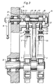
- Fig.3 shows the arrangement in accordance with the invention from the side and partly in section.
- the arrangement in accordance with the invention is intended for the application of pressure during the forming and sealing of packing container bottoms of the type which comprises a number of panels separated by means of crease lines, which are folded together so that they partly overlap each other and are sealed with the help of heat and pressure.
- the arrangement is intended first and foremost to be used on a machine of the principal type as illustrated in the said Swedish patent no. 361.857, to which reference is made.
- This type of packing machine is fed with, or converts a material web fed to it to, tubular, flattened blanks 1 ( Figure 1) which are manufactured from a flexible packing laminate comprising a relatively rigid carrier layer of e.g. paper which is coated on both sides with thermoplastic, liquid-tight and sealable material.
- the blanks are provided with a number of crease lines so that they are divided in a known manner into side wall panels and bottom and top wall panels. On feeding out from the magazine the blanks are raised so that they obtain a substantially square cross-sectional shape, whereupon they are transported in their longitudinal direction and are applied over a mandrel 2 adapted to the shape of the blank on a mandrel wheel 3.
- the mandrel wheel can be single or double and every machine may comprise one or more mandrel wheels.
- the mandrel wheel When the blank has been applied to a mandrel the mandrel wheel is turned one step so that the bottom folding panels of the blank projecting outside the free end of the mandrel can be heated by means of a bottom furnace 4 which, preferably with the help of hot air, heats the thermoplastic material layers of the bottom wall panels to softening temperature, which is suitable for sealing.
- a bottom furnace 4 which, preferably with the help of hot air, heats the thermoplastic material layers of the bottom wall panels to softening temperature, which is suitable for sealing.
- a folding of the heated bottom wall panels takes place first of all so that these overlap one another and form a substantially plane bottom, which in subsequent processing stations with the help of pressure devices 5 is pressed together and cooled so that the panels are sealed to one another in a water-tight manner.
- the liquid-tight blank provided with the bottom can be drawn vertically downwards to a conveyor which transports the blank further in longitudinal direction of the machine.
- the blank at this will pass in the said order a top prefolder 6 which prefold the top wall panels slightly so as to facilitate the subsequent top closure.
- the blank is placed underneath a filler pipe 7, through which from a contents tank 8 contents are passed with the help of a pump 9 in the desired quantity into the packing container.
- the packing container then continues to stop in subsequent stations where a top furnace 10 of the hot-air type heats the top wall panels of the packing container so that the thermoplastic layers acquire an appropriate sealing temperature.
- top sealer 11 The sealing of the top end of the packing container takes place with the help of top sealer 11, whereupon the filled and closed packing container via dating devices 12 and feed-out conveyors 13 is discharged from the packing machine in finished condition.
- This type of machine just as the said processing stations, may be conventional and is not, therefore, described in any further detail.
- the arrangement in accordance with the invention, which is placed on the pressing-down stations of the mandrel wheel 3, is illustrated more closely in Figure 2 and 3.
- the pressing-down arrangement 14 is located slightly outside the area of rotation of the mandrel wheel 3 and is supported by means of a bracket 16 projecting from the machine frame 15.
- the machine frame 15 also carries a driving shaft 17, supported so that it can rotate, for the pressure application arrangement 14, this driving shaft 17 comprising at its inner end located in the frame 15 a lever arm 18 which is connected directly or indirectly to a cam (not shown) driven from the main shaft of the machine.
- the frame 15 also carries the mandrel wheel axle 19 of the mandrel wheel 3 which is also connected by means of a known motion transfer elements to the main driving shaft of the packing machine in such a manner that during the operation of the machine it performs a stepwise rotating movement.
- an eccentric shaft 20 which is mounted overhung. More particularly, its one end is mounted rotatably in a bush 21 mounted so that it can slide in the bracket 16, whilst its opposite end is connected via a flexible coupling 22 to the driving shaft 17.
- the flexible coupling 22 comprises a tongue 23 projecting from the end of the eccentric shaft 20, which engages in slidable manner in a groove 24 in the end surface of the driving shaft 17.
- the groove is located so that in the active position of the arrangement it is substantially in the plane which connects the axis of rotation of the mandrel wheel 3 (that is to say the centre axis of the mandrel wheel axle 19) to the centre axis of the eccentric shaft 20.
- the eccentric shaft 20 will be slightly movable in this plane during the operation of the machine.
- the two eccentrics 25 support the two pressure devices 5, each of which comprises a pressure shaft 26 which at its one end is mounted rotatably on the eccentric 25.
- the pressure shaft 26 extends through an opening in the side of the bracket 16 facing towards the mandrel wheel shaft 19 and supports on its opposite end a pressure plate 27 which by means of guiding elements 29 is connected to the pressure shaft 26, but is held at a distance from the same, with a predefined force, with the help of spring elements 28 in the form of precompressed, helical compression springs.
- tie rod 30 which links the eccentric shaft 20 and the mandrel wheel axle 19.
- the upper end of the tie rod is mounted rotatably around the centre portion of the eccentric shaft 20, that is to say the part of the shaft 20 which is between the two eccentrics 25.
- the tie rod extends out of the bracket 16 and its other end is mounted rotatably around the mandrel wheel axle 19 between the two mandrel wheels 3.
- the mounting of the tie rod 30 on the mandrel wheel axle has a play of maximum 1 mm which will be explained in more detail in the following.
- the two ends of the tie rod 30 are mounted on the respective axle so that the tie rod is halfway between the two pressure devices 5 and the two mandrel wheels 3 respectively, the tensile and compression forces arising during operation receiving equally long lever arms and being able to balance out one another.
- a raised, prefabricated, tubular packing container blank 1 is fed to the bottom pressing-down station having passed first, thanks to the stepwise rotation of the mandrel wheel, the heating station, where the bottom furnace 4 has heated the bottom portion of the packing container blank projecting from the mandrel end to such a temperature that the thermoplastic surface layer has attained its sealing temperature.
- the bottom wall panels of the blank 1 are folded in conventional manner in the crease lines provided so that a substantially flat bottom is produced where the bottom wall panels partly overlap one another and can be sealed in a liquid-tight manner.
- the sealing is carried out in that the pressure plate 27 is moved in the direction towards the end surface of the actual mandrel 2 which a moment before through rotation of the mandrel wheel 3 has been moved to a position axially in line with the pressure device 5.
- the pressure device 5 at this will press together with a predefined force, determined by the precompressed spring elements 28, the end wall panels partially overlapping one another, so that the still soft thermoplastic material joins the panels to each other in a liquid-tight manner, as a result of which, after cooling, a liquid-tight, substantially plane packing container bottom is formed.
- the lever arm 18 of the driving shaft 17 is acted upon from a cam linked to the main driving shaft of the machine so that the driving shaft 17 performs a turning movement, at the end of which the groove 24 in the end of the shaft 17 is substantially in a plane which extends through the eccentric shaft as well as the mandrel wheel axle 19.
- the eccentric shaft 20 is turned to a corresponding degree so that the two eccentrics displace the pressure shafts 26 mounted on the eccentrics in the direction towards the mandrel wheel axle 19.
- the pressure plates 27 come to rest against the end wall panels folded down over the free end surfaces of the mandrels 2, and these are pressed together with a predefined force which is determined by the spring elements 28.
- the pressure shafts 26 have a slightly larger movement than the free space between the end surfaces of the mandrels 2 and the pressure plates 27, and the pressure shaft 26, therefore, move a little further in the direction towards the mandrel wheel axle 19 during continued compression by the spring elements 28.
- the resistance against movement of the pressure shafts 26 generated at this brings about that the pressure shafts 26 via their ends mounted on the eccentrics 25 slightly lift the eccentric shaft 20 (in the direction from the mandrel wheel axle 19; that is to say upwards in Fig.3) , which is possible owing to the eccentric shaft being mounted overhung.
- the tongue 23 of the eccentric shaft will slide upwards a little ( Figure 3) in the groove 24, and at the opposite end of the eccentric shaft the bush 21, in a corresponding manner, will slide upwards a little in the groove provided in the bracket 16.
- the eccentric shaft 20 is slightly displaced at this (approx. 0.5 - 1 mm) in the direction from the mandrel wheel axle 19 in the plane which is common for the mandrel wheel axle and the eccentric shaft, and since the tie rod 30 is mounted so that it can rotate on the centre portion of the eccentric shaft 20, the tie rod 30 too will be displaced slightly in the same direction.
- the movement of the tie rod 30 is limited by the play in its bearing surrounding the mandrel wheel axle 19, this play preferabl;y amounting to 0.5 - 1 mm.
Landscapes
- Engineering & Computer Science (AREA)
- Mechanical Engineering (AREA)
- Making Paper Articles (AREA)
- Basic Packing Technique (AREA)
- Auxiliary Devices For And Details Of Packaging Control (AREA)
- Supplying Of Containers To The Packaging Station (AREA)
- Closing Of Containers (AREA)
- Encapsulation Of And Coatings For Semiconductor Or Solid State Devices (AREA)
- Buffer Packaging (AREA)
- Containers And Plastic Fillers For Packaging (AREA)
- Package Closures (AREA)
Claims (6)
- Anordnung zum Aufbringen von Druck an einer Verpackungsmaschine, die ein schrittweise drehbares Dornrad (3) mit radialen Dornen (2) zur Aufnahme von Verpackungsbehälterformlingen (1) zum Formen der Behälterböden der Formlinge aufweist, mit einer Welle (20) mit exzentrisch angeordneten Teilen (25), wobei diese Welle einerseits mit Druckeinrichtungen (5), die mit den Dornen (2) zusammenwirken, und andererseits mit einer Einrichtung zur Absorption von Zugkräften verbunden ist und diese Einrichtung mit dem Dornrad (3) verbunden ist,
dadurch gekennzeichnet,
daß die Einrichtung zur Aufnahme von Zugkräften eine Verbindungsstange (30) aufweist, deren eines Ende an der exzentrisch angeordnete Teile (25) aufweisenden Welle (20) und deren entgegengesetztes Ende an einer Dornradachse (19) befestigt ist. - Anordnung nach Anspruch 1,
dadurch gekennzeichnet,
daß bei Maschinen mit zwei parallelen Dornrädern (3) die Verbindungsstange (30) zwischen den Druckeinrichtungen (5) angeordnet ist. - Anordnung nach einem oder mehreren der vorhergehenden Ansprüche,
dadurch gekennzeichnet,
daß die exzentrisch angeordnete Teile (25) aufweisende Welle im Maschinengestell (15) einseitig befestigt ist. - Anordnung nach Anspruch 3,
dadurch gekennzeichnet,
daß die Exzenterwelle (20) im wesentlichen in einer Ebene verlagerbar ist, die die Drehachse des Dornrads (3) mit der exzentrisch angeordnete Teile (25) aufweisenden Welle verbindet. - Anordnung nach Anspruch 4,
dadurch gekennzeichnet,
daß ein Ende der exzentrisch angeordnete Teile (25) aufweisenden Welle (20) über eine flexible Kupplung (24) mit einem Schlitz (24) mit einer Antriebswelle (17) verbunden ist. - Anordnung nach einem oder mehreren der vorhergehenden Ansprüche,
dadurch gekennzeichnet,
daß die Druckeinrichtung (5) eine Druckplatte (27) aufweist, die mit der exzentrisch angeordnete Teile (25) aufweisenden Welle (20) über druckvorgespannte Federn (28) verbunden ist.
Priority Applications (1)
| Application Number | Priority Date | Filing Date | Title |
|---|---|---|---|
| AT87105662T ATE71043T1 (de) | 1986-04-18 | 1987-04-16 | Vorrichtung auf einer verpackungsmaschine. |
Applications Claiming Priority (2)
| Application Number | Priority Date | Filing Date | Title |
|---|---|---|---|
| SE8601781 | 1986-04-18 | ||
| SE8601781A SE457874B (sv) | 1986-04-18 | 1986-04-18 | Anordning vid foerpackningsmaskin |
Publications (3)
| Publication Number | Publication Date |
|---|---|
| EP0242805A2 EP0242805A2 (de) | 1987-10-28 |
| EP0242805A3 EP0242805A3 (en) | 1988-10-26 |
| EP0242805B1 true EP0242805B1 (de) | 1992-01-02 |
Family
ID=20364250
Family Applications (1)
| Application Number | Title | Priority Date | Filing Date |
|---|---|---|---|
| EP87105662A Expired - Lifetime EP0242805B1 (de) | 1986-04-18 | 1987-04-16 | Vorrichtung auf einer Verpackungsmaschine |
Country Status (13)
| Country | Link |
|---|---|
| US (1) | US4986058A (de) |
| EP (1) | EP0242805B1 (de) |
| JP (1) | JP2582773B2 (de) |
| AT (1) | ATE71043T1 (de) |
| AU (1) | AU583984B2 (de) |
| CA (1) | CA1303890C (de) |
| DE (1) | DE3775602D1 (de) |
| DK (1) | DK161954C (de) |
| ES (1) | ES2029237T3 (de) |
| MX (1) | MX168641B (de) |
| NO (1) | NO168025C (de) |
| SE (1) | SE457874B (de) |
| SU (1) | SU1572405A3 (de) |
Families Citing this family (15)
| Publication number | Priority date | Publication date | Assignee | Title |
|---|---|---|---|---|
| JP2796536B2 (ja) * | 1989-01-20 | 1998-09-10 | 四国化工機株式会社 | 容器底部圧着装置 |
| DE4140037C2 (de) * | 1991-12-05 | 1995-06-22 | Tetra Pak Gmbh | Vorrichtung zum Verschweißen einer Siegelnaht an einer Packung |
| DE4313325C2 (de) * | 1993-04-23 | 2000-01-13 | Tetra Pak Gmbh | Vorrichtung zum Füllen und Verschließen von Packungen |
| US5555708A (en) * | 1995-04-21 | 1996-09-17 | Elopak Systems A.G. | Pressure closing mechanism |
| US5743997A (en) * | 1996-03-29 | 1998-04-28 | Elopak Systems Ag | Sheet material sealing arrangement |
| US6094884A (en) * | 1997-10-21 | 2000-08-01 | Tetra Laval Holdings & Finance, Sa | Forming apparatus for an elevated bottom carton |
| US5845840A (en) * | 1997-10-21 | 1998-12-08 | Tetra Laval Holdings & Finance, S.A. | Elevated bottom carton |
| US6609355B2 (en) * | 2001-10-15 | 2003-08-26 | International Paper Company | Adjustable carton stop |
| US6669614B2 (en) * | 2001-10-15 | 2003-12-30 | International Paper | Method and apparatus for closing open end of carton blank |
| ITTO20020367A1 (it) * | 2002-05-03 | 2003-11-03 | Tetra Laval Holdings E Finance | Metodo e macchina confezionatrice per la realizzazione di confezioni sigillate di prodotti alimentari varsabili a partire da sbozzati pre-tr |
| ITBO20020486A1 (it) * | 2002-07-25 | 2004-01-26 | Azionaria Costruzioni Acma Spa | Macchina per formare contenitori , in particolare contenitori per prodotti alimentari |
| DE102009042057A1 (de) * | 2009-09-10 | 2011-03-24 | Sig Technology Ag | Vorrichtung und Verfahren zum Verpressen |
| DE102010050502A1 (de) * | 2010-11-08 | 2012-05-10 | Sig Technology Ag | Vorrichtung und Verfahren zur Herstellung einer Verpackung |
| CN103224071B (zh) * | 2013-05-13 | 2014-12-17 | 瑞安市明瑞包装机械有限公司 | 多工位加工的纸塑包装机 |
| DE102015104102A1 (de) | 2015-03-19 | 2016-09-22 | Sig Technology Ag | Dornrad zur Herstellung von Verpackungen |
Family Cites Families (6)
| Publication number | Priority date | Publication date | Assignee | Title |
|---|---|---|---|---|
| US3566762A (en) * | 1965-06-07 | 1971-03-02 | Fmc Corp | Carton-forming apparatus |
| US3486423A (en) * | 1966-06-03 | 1969-12-30 | Illinois Creamery Supply Co | Machine for automatically forming,filling,closing and sealing plastic coated gable top cartons of paperboard or the like |
| SE361022B (de) * | 1968-10-30 | 1973-10-15 | Tetra Pak Int | |
| SE335090B (de) * | 1968-10-30 | 1971-05-10 | Tetra Pak Int | |
| SE454678B (sv) * | 1984-09-12 | 1988-05-24 | Tetra Pak Ab | Maskin for tillverkning av forpackningsbehallare |
| JP5424084B2 (ja) | 2006-09-13 | 2014-02-26 | 東邦化学工業株式会社 | 新規なポリカルボン酸系重合体 |
-
1986
- 1986-04-18 SE SE8601781A patent/SE457874B/sv not_active IP Right Cessation
-
1987
- 1987-04-13 NO NO871562A patent/NO168025C/no not_active IP Right Cessation
- 1987-04-14 DK DK193587A patent/DK161954C/da active
- 1987-04-15 CA CA000534794A patent/CA1303890C/en not_active Expired - Lifetime
- 1987-04-15 MX MX006089A patent/MX168641B/es unknown
- 1987-04-16 AU AU71743/87A patent/AU583984B2/en not_active Ceased
- 1987-04-16 DE DE8787105662T patent/DE3775602D1/de not_active Expired - Lifetime
- 1987-04-16 AT AT87105662T patent/ATE71043T1/de not_active IP Right Cessation
- 1987-04-16 US US07/038,982 patent/US4986058A/en not_active Expired - Lifetime
- 1987-04-16 EP EP87105662A patent/EP0242805B1/de not_active Expired - Lifetime
- 1987-04-16 ES ES198787105662T patent/ES2029237T3/es not_active Expired - Lifetime
- 1987-04-17 JP JP62095000A patent/JP2582773B2/ja not_active Expired - Fee Related
- 1987-04-17 SU SU874202459A patent/SU1572405A3/ru active
Also Published As
| Publication number | Publication date |
|---|---|
| DK193587A (da) | 1987-10-19 |
| US4986058A (en) | 1991-01-22 |
| CA1303890C (en) | 1992-06-23 |
| EP0242805A3 (en) | 1988-10-26 |
| NO168025B (no) | 1991-09-30 |
| ATE71043T1 (de) | 1992-01-15 |
| SE457874B (sv) | 1989-02-06 |
| SE8601781D0 (sv) | 1986-04-18 |
| DK161954C (da) | 1992-02-03 |
| NO871562D0 (no) | 1987-04-13 |
| MX168641B (es) | 1993-06-02 |
| AU583984B2 (en) | 1989-05-11 |
| JP2582773B2 (ja) | 1997-02-19 |
| JPS62297140A (ja) | 1987-12-24 |
| NO168025C (no) | 1992-01-08 |
| DK193587D0 (da) | 1987-04-14 |
| SE8601781L (sv) | 1987-10-19 |
| SU1572405A3 (ru) | 1990-06-15 |
| DE3775602D1 (de) | 1992-02-13 |
| ES2029237T3 (es) | 1992-08-01 |
| AU7174387A (en) | 1987-10-22 |
| DK161954B (da) | 1991-09-02 |
| EP0242805A2 (de) | 1987-10-28 |
| NO871562L (no) | 1987-10-19 |
Similar Documents
| Publication | Publication Date | Title |
|---|---|---|
| EP0242805B1 (de) | Vorrichtung auf einer Verpackungsmaschine | |
| EP0217282B1 (de) | Verfahren und Maschine zur Herstellung von Verpackungsbehältern | |
| EP0097984B1 (de) | Anordnung für die Behandlung eines Verpackungsbehälters | |
| CA1187056A (en) | Filled container end seal folding system with intermittent motion conveyor | |
| US4510732A (en) | Machine for the processing of packing containers | |
| US3788033A (en) | Packaging machine | |
| EP0091712B1 (de) | Verfahren und Vorrichtung zur Behandlung einer Materialbahn | |
| US8231514B2 (en) | Folding assembly and method for producing a gable portion of a sealed package of a pourable food product | |
| US4838847A (en) | Packaging machine | |
| CN109625361B (zh) | 屋顶纸盒包装机 | |
| US4528803A (en) | Machine for the fabrication, filling, and sealing of packages | |
| AU597643B2 (en) | An arrangement on packing machines | |
| EP0112605B1 (de) | Verpackung | |
| EP0798105B1 (de) | Verpackungsmaschine | |
| CN114229115B (zh) | 一种新型大容量饮品生产线开箱机 | |
| CN112537511B (zh) | 一种半自动纸盒灌装设备 | |
| US4717371A (en) | Apparatus for making bulk containers from laminated paperboard | |
| GB2165796A (en) | Toggle lever drive in material processing apparatus | |
| HU227146B1 (en) | Packaging machine | |
| JPH08318583A (ja) | 加圧式閉鎖装置 | |
| US2480176A (en) | Method of assembling containers | |
| CA1174157A (en) | Machine for manufacturing, filling and sealing packages | |
| CN120481374A (zh) | 一种密封包装袋热压复合生产线 | |
| US20070135284A1 (en) | Carton bottom sealer apparatus and method |
Legal Events
| Date | Code | Title | Description |
|---|---|---|---|
| PUAI | Public reference made under article 153(3) epc to a published international application that has entered the european phase |
Free format text: ORIGINAL CODE: 0009012 |
|
| AK | Designated contracting states |
Kind code of ref document: A2 Designated state(s): AT BE CH DE ES FR GB IT LI NL SE |
|
| PUAL | Search report despatched |
Free format text: ORIGINAL CODE: 0009013 |
|
| AK | Designated contracting states |
Kind code of ref document: A3 Designated state(s): AT BE CH DE ES FR GB IT LI NL SE |
|
| 17P | Request for examination filed |
Effective date: 19890316 |
|
| RAP1 | Party data changed (applicant data changed or rights of an application transferred) |
Owner name: AB TETRA PAK |
|
| 17Q | First examination report despatched |
Effective date: 19901114 |
|
| GRAA | (expected) grant |
Free format text: ORIGINAL CODE: 0009210 |
|
| ITF | It: translation for a ep patent filed | ||
| AK | Designated contracting states |
Kind code of ref document: B1 Designated state(s): AT BE CH DE ES FR GB IT LI NL SE |
|
| REF | Corresponds to: |
Ref document number: 71043 Country of ref document: AT Date of ref document: 19920115 Kind code of ref document: T |
|
| REF | Corresponds to: |
Ref document number: 3775602 Country of ref document: DE Date of ref document: 19920213 |
|
| ET | Fr: translation filed | ||
| REG | Reference to a national code |
Ref country code: ES Ref legal event code: FG2A Ref document number: 2029237 Country of ref document: ES Kind code of ref document: T3 |
|
| PLBE | No opposition filed within time limit |
Free format text: ORIGINAL CODE: 0009261 |
|
| STAA | Information on the status of an ep patent application or granted ep patent |
Free format text: STATUS: NO OPPOSITION FILED WITHIN TIME LIMIT |
|
| 26N | No opposition filed | ||
| EAL | Se: european patent in force in sweden |
Ref document number: 87105662.8 |
|
| PGFP | Annual fee paid to national office [announced via postgrant information from national office to epo] |
Ref country code: NL Payment date: 20000331 Year of fee payment: 14 |
|
| PGFP | Annual fee paid to national office [announced via postgrant information from national office to epo] |
Ref country code: GB Payment date: 20000403 Year of fee payment: 14 Ref country code: CH Payment date: 20000403 Year of fee payment: 14 Ref country code: AT Payment date: 20000403 Year of fee payment: 14 |
|
| PGFP | Annual fee paid to national office [announced via postgrant information from national office to epo] |
Ref country code: BE Payment date: 20000421 Year of fee payment: 14 |
|
| PGFP | Annual fee paid to national office [announced via postgrant information from national office to epo] |
Ref country code: ES Payment date: 20000510 Year of fee payment: 14 |
|
| PG25 | Lapsed in a contracting state [announced via postgrant information from national office to epo] |
Ref country code: GB Free format text: LAPSE BECAUSE OF NON-PAYMENT OF DUE FEES Effective date: 20010416 Ref country code: AT Free format text: LAPSE BECAUSE OF NON-PAYMENT OF DUE FEES Effective date: 20010416 |
|
| PG25 | Lapsed in a contracting state [announced via postgrant information from national office to epo] |
Ref country code: ES Free format text: LAPSE BECAUSE OF NON-PAYMENT OF DUE FEES Effective date: 20010417 |
|
| PG25 | Lapsed in a contracting state [announced via postgrant information from national office to epo] |
Ref country code: BE Free format text: LAPSE BECAUSE OF NON-PAYMENT OF DUE FEES Effective date: 20010430 |
|
| PG25 | Lapsed in a contracting state [announced via postgrant information from national office to epo] |
Ref country code: LI Free format text: LAPSE BECAUSE OF NON-PAYMENT OF DUE FEES Effective date: 20010515 Ref country code: CH Free format text: LAPSE BECAUSE OF NON-PAYMENT OF DUE FEES Effective date: 20010515 |
|
| BERE | Be: lapsed |
Owner name: TETRA PAK A.B. Effective date: 20010430 |
|
| PG25 | Lapsed in a contracting state [announced via postgrant information from national office to epo] |
Ref country code: NL Free format text: LAPSE BECAUSE OF NON-PAYMENT OF DUE FEES Effective date: 20011101 |
|
| GBPC | Gb: european patent ceased through non-payment of renewal fee |
Effective date: 20010416 |
|
| REG | Reference to a national code |
Ref country code: CH Ref legal event code: PL |
|
| NLV4 | Nl: lapsed or anulled due to non-payment of the annual fee |
Effective date: 20011101 |
|
| REG | Reference to a national code |
Ref country code: ES Ref legal event code: FD2A Effective date: 20030203 |
|
| PGFP | Annual fee paid to national office [announced via postgrant information from national office to epo] |
Ref country code: FR Payment date: 20030418 Year of fee payment: 17 |
|
| PGFP | Annual fee paid to national office [announced via postgrant information from national office to epo] |
Ref country code: SE Payment date: 20030422 Year of fee payment: 17 |
|
| PGFP | Annual fee paid to national office [announced via postgrant information from national office to epo] |
Ref country code: DE Payment date: 20030430 Year of fee payment: 17 |
|
| PG25 | Lapsed in a contracting state [announced via postgrant information from national office to epo] |
Ref country code: SE Free format text: LAPSE BECAUSE OF NON-PAYMENT OF DUE FEES Effective date: 20040417 |
|
| PG25 | Lapsed in a contracting state [announced via postgrant information from national office to epo] |
Ref country code: DE Free format text: LAPSE BECAUSE OF NON-PAYMENT OF DUE FEES Effective date: 20041103 |
|
| EUG | Se: european patent has lapsed | ||
| PG25 | Lapsed in a contracting state [announced via postgrant information from national office to epo] |
Ref country code: FR Free format text: LAPSE BECAUSE OF NON-PAYMENT OF DUE FEES Effective date: 20041231 |
|
| REG | Reference to a national code |
Ref country code: FR Ref legal event code: ST |
|
| PG25 | Lapsed in a contracting state [announced via postgrant information from national office to epo] |
Ref country code: IT Free format text: LAPSE BECAUSE OF NON-PAYMENT OF DUE FEES;WARNING: LAPSES OF ITALIAN PATENTS WITH EFFECTIVE DATE BEFORE 2007 MAY HAVE OCCURRED AT ANY TIME BEFORE 2007. THE CORRECT EFFECTIVE DATE MAY BE DIFFERENT FROM THE ONE RECORDED. Effective date: 20050416 |