EP0242756A2 - Roue à pivot pour chariot de transport - Google Patents
Roue à pivot pour chariot de transport Download PDFInfo
- Publication number
- EP0242756A2 EP0242756A2 EP87105428A EP87105428A EP0242756A2 EP 0242756 A2 EP0242756 A2 EP 0242756A2 EP 87105428 A EP87105428 A EP 87105428A EP 87105428 A EP87105428 A EP 87105428A EP 0242756 A2 EP0242756 A2 EP 0242756A2
- Authority
- EP
- European Patent Office
- Prior art keywords
- fork
- head
- roller
- fastening pin
- roller according
- Prior art date
- Legal status (The legal status is an assumption and is not a legal conclusion. Google has not performed a legal analysis and makes no representation as to the accuracy of the status listed.)
- Withdrawn
Links
Images

Classifications
-
- B—PERFORMING OPERATIONS; TRANSPORTING
- B60—VEHICLES IN GENERAL
- B60B—VEHICLE WHEELS; CASTORS; AXLES FOR WHEELS OR CASTORS; INCREASING WHEEL ADHESION
- B60B33/00—Castors in general; Anti-clogging castors
- B60B33/0002—Castors in general; Anti-clogging castors assembling to the object, e.g. furniture
Definitions
- the invention relates to a roller for transport trolleys, in particular for basket-type shopping trolleys, with two fork legs, which are mounted on the axis of an impeller and are connected to one another via a wall bridge, and which are fastened to a separate fork head which consists of two complementary fastening bolts with a bearing receptacle formed during assembly encompassing head pieces is formed.
- the center plane of the flange should lie approximately in the vertical plane lying through the center of the roller and therefore in the center plane of the trellis, a precise manufacture of the fastening pin on the one hand and its exact connection to the fork head on the other hand is required.
- This connection is carried out as a factory pressing process and the roller thus prepared is then to be connected to the trolley by means of further fastening means. The manufacturing and assembly effort of such a roller is accordingly considerable.
- the object of the invention is to provide a technically simple and easy to assemble mounting option for a roller of the type mentioned on a trolley.
- the mounting pin is an integral part of the trolley. This allows the roller with its fork head to be simply attached to the carriage-side mounting pin.
- a particularly simple, production-related and assembly-related fastening possibility results from the assembly of trolleys composed of bars to form a latticework, as is particularly the case in large department stores, supermarkets and the like. are to be found.
- the fastening pin is preferably formed by a vertically extending extension of a trellis.
- the fastening pin is enclosed by an axial retaining ring arranged in an annular groove in the bearing receptacle of the fork head.
- This axial retaining ring may preferably be formed by a clamping ring that encompasses the fastening pin.
- a plurality of axial retaining rings can also be arranged in one or more ring grooves if this is necessary.
- the swivel castor can be easily from the underside of the trolley on the attach the associated fastening pin, which is generally arranged in the four corner areas of the transport carriage.
- the head pieces have a bearing attachment on the top for a deflector wheel.
- This deflector wheel which can be rotated in the horizontal plane around the bearing shoulder, protrudes laterally beyond the fork head and allows the trolley to slide sideways at obstacles such as doors, walls or the like.
- the bearing approach is advantageously designed as a locking ring, so that a simple assembly of the deflector is possible.
- This deflector wheel itself is advantageously designed as a plate disk, which overlaps the upper region of the fork head with a cavity.
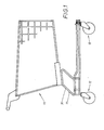
- FIG. 1 shows a transport trolley 10 designed as a basket-like shopping trolley, the base frame 11 of which is equipped at its four corner regions with a roller 12 in each case.
- Each of the four castors can have a wheel fork that can be pivoted about a fastening pin, but it is also possible to arrange a fixed castor on two opposite corner areas on one narrow side of the base frame, while the other narrow side of the base frame can be equipped with a pivotable castor on its two opposite corner areas can.
- the roller 12 indicated in FIG. 1 and shown in FIGS. 2 to 4 has a wheel fork
- the Fork body is formed from a one-piece sheet metal blank by connecting two fork legs 13 and 14 to one another by means of a U-shaped folding, by means of a vertically extending wall bridge 15 arranged in one piece therebetween.
- Each fork leg 13 and 14 has in its lower free end a bearing bore 16 for an indicated in Figs. 2 and 4 axis 17 of the impeller 18, while a rectangular recess 19 is arranged in the wall bridge 15 of the fork body, which serves as a support for the Serves fork head 20 inserted into the top of the fork body.
- This fork head consists of two head pieces 21 and 22 which complement one another and fit together.
- the head pieces 21 and 22 have lugs 23 on the upper side which, in the assembled state of the head pieces 21 and 22, form a circumferential bar which overlaps the wall bridge 15 and the fork legs 13 and 14 on the upper side.
- a projection 24, which projects into the recess 19 of the wall bridge and is complementary to a strip, is arranged on the two head pieces 21 and 22, which together with the extension 23 and the fork legs 13 and 14 and the head pieces 21 and 22 crossing rivet bolts 25 secure the position of the fork head 20 with respect to the fork legs 13 and 14 in their connection position.
- a fitting receptacle 26 may be recessed on a head piece 21 on the side facing the other head piece 22, into which a fitting shoulder 27 arranged on the other head piece 22 engages in a closing manner.
- a semi-cylindrical, blind hole-like recess 28 is arranged, which in the assembled state of the head pieces 21 and 22 complement one another to form a blind hole-like bearing receptacle 29 for a fastening pin 30.
- the mounting pin 30 engaging in the bearing receptacle 29 of the fork head 20 is part of the base frame 11 on the trolley 10 and, in the exemplary embodiment shown in FIGS. 2 and 3, consists of the extension 32 of a lattice rod 31 30, the fork head 20 with the fork legs 13 and 14 attached to it and the wheel 18 arranged between them on the axle 17 can be pushed on from below. Since the head pieces 21 and 22 forming the fork head 20 can be made of a slidable plastic, the slide bearing achieved is completely sufficient for the pivoting movement of the roller 12.
- the fork head 20 is provided in the bearing receptacle 29 with an annular groove 33 which forms the receiving space for an axial retaining ring 34.
- This axial retaining ring can be designed, for example, as a clamping ring that clamps the fastening pin and has a holding force that is sufficient to prevent the roller attached to the fastening pin from sliding off.
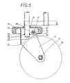
- each head piece has on its upper side a half-ring-shaped bearing projection 35 surrounding the recess 28.
- These bearing approaches 35 complement one another to form a bearing ring comprising the mounting pin 30, on which a plate-shaped deflector 36 is rotatably mounted so that it can run in the horizontal direction in the upper region of the wheel fork.
- the bearing boss 35 is provided with locking projections 38 on the top, so that the deflector 36 for Arrangement on the clevis 20 can be snapped on.
- the plate shape of the deflector wheel and its bearing shape is selected so that the circumferential ring of the deflector wheel forming the tread engages around the upper region of the wheel fork, ie that the wheel fork is partially immersed in the cavity 37 of the deflector wheel.
- roller according to the invention in trolleys which have closed wall and floor parts and in which the fastening pin 30 is designed as a stub shaft projecting in the vertical direction.
- a fastening pin can, for example, also be fastened in a bracket-like holder on the underside of the bottom of a transport vehicle, for example by means of screws, rivets, welding or the like.
Landscapes
- Engineering & Computer Science (AREA)
- Mechanical Engineering (AREA)
- Handcart (AREA)
- Mounting Of Bearings Or Others (AREA)
Applications Claiming Priority (2)
| Application Number | Priority Date | Filing Date | Title |
|---|---|---|---|
| DE19863613136 DE3613136C2 (de) | 1986-04-18 | 1986-04-18 | Laufrolle für Transportwagen |
| DE3613136 | 1986-04-18 |
Publications (2)
| Publication Number | Publication Date |
|---|---|
| EP0242756A2 true EP0242756A2 (fr) | 1987-10-28 |
| EP0242756A3 EP0242756A3 (fr) | 1989-03-15 |
Family
ID=6299003
Family Applications (1)
| Application Number | Title | Priority Date | Filing Date |
|---|---|---|---|
| EP87105428A Withdrawn EP0242756A3 (fr) | 1986-04-18 | 1987-04-11 | Roue à pivot pour chariot de transport |
Country Status (2)
| Country | Link |
|---|---|
| EP (1) | EP0242756A3 (fr) |
| DE (1) | DE3613136C2 (fr) |
Cited By (2)
| Publication number | Priority date | Publication date | Assignee | Title |
|---|---|---|---|---|
| EP0412625A1 (fr) * | 1989-08-04 | 1991-02-13 | Guy-Raymond Engineering Company Limited | Roulette à pivot |
| WO1997043135A1 (fr) * | 1996-05-15 | 1997-11-20 | Wanzl Gmbh & Co. Entwicklungs-Kg | Chariot transporteur deplaçable manuellement |
Families Citing this family (1)
| Publication number | Priority date | Publication date | Assignee | Title |
|---|---|---|---|---|
| CN105946930B (zh) * | 2016-05-27 | 2018-08-03 | 国网山东省电力公司济南供电公司 | 一种自卸车 |
Family Cites Families (4)
| Publication number | Priority date | Publication date | Assignee | Title |
|---|---|---|---|---|
| GB415215A (en) * | 1933-05-02 | 1934-08-23 | Compressed Rubber Products Ltd | Improvements in or relating to brackets for stationary or swivelling castors or the like |
| US2706135A (en) * | 1950-05-20 | 1955-04-12 | Murray Ohio Mfg Co | Wheel construction |
| FR2191630A5 (fr) * | 1972-06-29 | 1974-02-01 | Reunis Sa Ateliers | |
| EP0161108A3 (fr) * | 1984-05-04 | 1987-05-27 | B. Houston Rehrig | Montage de roue |
-
1986
- 1986-04-18 DE DE19863613136 patent/DE3613136C2/de not_active Expired - Fee Related
-
1987
- 1987-04-11 EP EP87105428A patent/EP0242756A3/fr not_active Withdrawn
Cited By (2)
| Publication number | Priority date | Publication date | Assignee | Title |
|---|---|---|---|---|
| EP0412625A1 (fr) * | 1989-08-04 | 1991-02-13 | Guy-Raymond Engineering Company Limited | Roulette à pivot |
| WO1997043135A1 (fr) * | 1996-05-15 | 1997-11-20 | Wanzl Gmbh & Co. Entwicklungs-Kg | Chariot transporteur deplaçable manuellement |
Also Published As
| Publication number | Publication date |
|---|---|
| DE3613136C2 (de) | 1993-09-30 |
| DE3613136A1 (de) | 1987-10-22 |
| EP0242756A3 (fr) | 1989-03-15 |
Similar Documents
| Publication | Publication Date | Title |
|---|---|---|
| DE69015133T2 (de) | Segmentierte Seitenwand für Wagen. | |
| DE4406749C2 (de) | Fahrbarer Reinigungswagen mit Anhänger | |
| DE2546969C3 (de) | Transportwagen für Selbstbedienungsläden | |
| DE69002524T2 (de) | Lenkrollenfeststellvorrichtung. | |
| DE2926596A1 (de) | Transportkarre | |
| DE8523747U1 (de) | Transportwagen, insbesondere für die Kundschaft in Selbstbedienungsläden | |
| EP0569988B1 (fr) | Chariot de transport pour objets de type palette | |
| DE3613136C2 (de) | Laufrolle für Transportwagen | |
| EP1358637A2 (fr) | Serrure a consigne pour un chariot de transport | |
| DE4221541C2 (de) | Gebremste Lenkrolle | |
| DE2543771B2 (de) | Schmutz- und Frischwäschetransportwagen für Krankenhäuser, Hotels und Heime | |
| EP0848669B1 (fr) | Chassis pour un chariot de transport deplaceable manuellement | |
| DE29518266U1 (de) | Hubfahrzeug zum Anheben, Transportieren und Absenken von Transportgut | |
| DE69114471T2 (de) | Ausbreitbarer Transportwagen und dazu passende Spuranordnung. | |
| DE19643121A1 (de) | Von Hand bewegbarer Transportwagen | |
| DE202014000039U1 (de) | Tragwagen für Gokarts | |
| DE69204758T2 (de) | Runge für eine Ladefläche und Methode zum Montieren einer Schliess- und Beeinflussungsvorrichtung in dieser. | |
| EP0432515A1 (fr) | Chariot à provisions | |
| DE3841004A1 (de) | Mit entsprechenden wagen schachtelbarer schubgepaeckwagen | |
| DE2107707A1 (de) | Freileitungs-Fahrwagen | |
| DE4031396A1 (de) | Von hand bewegbarer transportwagen, insbesondere einkaufswagen | |
| DE3931091A1 (de) | Einkaufswagen | |
| EP0418748A1 (fr) | Chariot d'achat | |
| EP0837780A1 (fr) | Chariot transporteur depla able manuellement | |
| DE7635224U1 (de) | Einkaufswagen mit kunststoffkorb |
Legal Events
| Date | Code | Title | Description |
|---|---|---|---|
| PUAI | Public reference made under article 153(3) epc to a published international application that has entered the european phase |
Free format text: ORIGINAL CODE: 0009012 |
|
| AK | Designated contracting states |
Kind code of ref document: A2 Designated state(s): FR GB IT |
|
| PUAL | Search report despatched |
Free format text: ORIGINAL CODE: 0009013 |
|
| AK | Designated contracting states |
Kind code of ref document: A3 Designated state(s): FR GB IT |
|
| STAA | Information on the status of an ep patent application or granted ep patent |
Free format text: STATUS: THE APPLICATION HAS BEEN WITHDRAWN |
|
| 18W | Application withdrawn |
Withdrawal date: 19890826 |
|
| RIN1 | Information on inventor provided before grant (corrected) |
Inventor name: SCHULTE, ARNOLF, DIPL.-ING. |