EP0242728A2 - Kernbohrwerkzeug für Gesteinsbohrungen - Google Patents
Kernbohrwerkzeug für Gesteinsbohrungen Download PDFInfo
- Publication number
- EP0242728A2 EP0242728A2 EP87105301A EP87105301A EP0242728A2 EP 0242728 A2 EP0242728 A2 EP 0242728A2 EP 87105301 A EP87105301 A EP 87105301A EP 87105301 A EP87105301 A EP 87105301A EP 0242728 A2 EP0242728 A2 EP 0242728A2
- Authority
- EP
- European Patent Office
- Prior art keywords
- core
- shaft
- tube
- drilling fluid
- core tube
- Prior art date
- Legal status (The legal status is an assumption and is not a legal conclusion. Google has not performed a legal analysis and makes no representation as to the accuracy of the status listed.)
- Granted
Links
Images
Classifications
-
- E—FIXED CONSTRUCTIONS
- E21—EARTH OR ROCK DRILLING; MINING
- E21B—EARTH OR ROCK DRILLING; OBTAINING OIL, GAS, WATER, SOLUBLE OR MELTABLE MATERIALS OR A SLURRY OF MINERALS FROM WELLS
- E21B4/00—Drives for drilling, used in the borehole
- E21B4/02—Fluid rotary type drives
-
- E—FIXED CONSTRUCTIONS
- E21—EARTH OR ROCK DRILLING; MINING
- E21B—EARTH OR ROCK DRILLING; OBTAINING OIL, GAS, WATER, SOLUBLE OR MELTABLE MATERIALS OR A SLURRY OF MINERALS FROM WELLS
- E21B25/00—Apparatus for obtaining or removing undisturbed cores, e.g. core barrels or core extractors
- E21B25/02—Apparatus for obtaining or removing undisturbed cores, e.g. core barrels or core extractors the core receiver being insertable into, or removable from, the borehole without withdrawing the drilling pipe
Definitions
- the invention relates to a core drilling tool for rock drilling according to the preamble of claim 1.
- the core tube is connected via a universal joint to the stator of a drilling fluid-driven motor which works according to the Moineau principle.
- the core tube is permanently installed, so that a core that has been drilled out can only be obtained after the tool has been taken up to the drilling platform and then dismantled.
- the central passage for drilling fluid in the stator of this tool forms a bypass to the working chambers of the motor and is used to supply drilling fluid to the interior of the core tube for cleaning before the drilling process begins - without starting the motor.
- a core drilling tool which is driven by a turbine and in which a core tube insert can be brought up to the drilling platform through a central passage in the turbine by means of a safety catch with an otherwise installed drilling tool.
- the invention has for its object to provide a core drilling tool that allows the extraction of cores in the installed state by separately pulling the core tube with special consideration of the use of a drilling fluid motor with a helical toothed rotor and a corresponding stator according to the Moineau principle for driving the drill bit .
- an embodiment of the core drilling tool according to the characterizing features of claim 1.
- the core tube By dimensioning the central passage of the shaft in comparison to the outer diameter of the core tube, the core tube can be pulled up through the shaft if necessary or inserted into the operating position from top to bottom.
- This feature also enables the core drilling tool to be used to extract multiple cores from the same borehole of an uncased seabed from a floating drilling platform.
- the design of the inner diameter of the hollow stator and of the connecting element taking into account the outer diameter of the core tube and the eccentricity of the motor, enables the stator to describe the eccentric movement caused by the rotor and stator geometry without coming into contact with the core tube and its central position affect.
- the locking device ensures the automatic axial fixation of the core tube in relation to the annular gap between the drill bit and the front end of the core tube after it has reached the operating position by gravity or with the additional support of the flushing water pumps.
- the seals between the core tube outer jacket and the inner wall of the shaft create a flush prevents passage through the interior of the stator, so that the entire drilling fluid flow has to take the way over the working space of the motor.
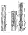
- the core drilling tool comprises a shank 1, which can be connected to a drill string (not shown) via a threaded sleeve 2.
- An outer tube 4 is rotatably mounted on the shaft 1 by means of a bearing arrangement 3 and carries a core drill bit or a core bit 5 at the lower end.
- the shaft 1 has a central passage 6 with the inner diameter d1 and is connected at the lower end via a threaded connection 7 to a thin-walled, flexible sleeve 8 serving as a connecting member.
- This sleeve is connected via a further threaded connection 9 to the hollow stator 10 of a drilling fluid driven motor 11.
- the rotor 12 of this motor is located on the inside of the outer tube 4.
- the rotor 12 and the stator 10 are provided with helical teeth and are in engagement with one another to form a working space 42.
- the engine works according to the so-called Moineau principle. If one of the two parts is fixed in its radial position in such a motor, the other part executes an eccentric path. Since in the present case the rotor 12 is fixed radially by the bearing of the outer tube 4 by means of the bearing arrangement 3, the stator 10 must describe this path. The corresponding radial displacement with respect to the shaft 1 while at the same time preventing a rotational movement is made possible by the flexible thin-walled sleeve 8.
- the diameter d2 of the stator 10 and of the flexible thin-walled sleeve 8 is larger by the value of the eccentricity e of the motor 11 than the diameter d1 of the central passage 6 in the shaft 1. This ensures that the diameter of the envelope of the eccentric assignment of the stator 10 has approximately the same diameter d3 as the central passage 6 of the shaft 1 with the diameter dl.
- a core tube 13 is arranged within the central passage 6 of the shaft 1 and in the interior formed by the flexible sleeve 8, the rotor 10 and the lower part of the outer tube 4.
- the core tube 13 comprises an inner tube 14, the lower end boundary 15 of which adjoins an inwardly extending shoulder 17 of the core bit 5 to form a gap 16 for the passage of drilling fluid.
- a latching device 18 is used for axially fixing the core tube 13.
- the latching fingers 23 are the walls of the S ülungsraums p in the drill string as well as the central passage 6 of the core sampler as long as compressed to the core tube 13, the position shown in the drawing has been reached and the latching fingers 23 with their approaches 24 can spread into the circumferential groove 25.
- the latching fingers 23 are designed as a segmented catch mandrel 27 and can be overlapped with a sleeve of a catch tool and released from the catch into the circumferential groove 25 by being pressed together.
- the core tube 13 can then be brought up to the drilling platform by means of a wire rope through the motor 11, the flexible thin-walled sleeve 8, the shaft 1 and the remaining drill pipe.
- the inner tube 14 of the core tube 13 is coupled to the latching device 18 by a pivot bearing 28.
- This pivot bearing 28 enables a relative rotation between the inner tube 14 with respect to the shaft 1 when the inner tube 14 is blocked by a core that has grown into it, but the linkage and thus the shaft 1 are also to be rotated. A relative rotation within the locking device 18, which could lead to premature wear of the locking elements, is thereby avoided.
- the inner tube 14 carries at the upper end a check valve device 29, consisting of a central bore 30, a ball 31 used to close the central bore 30 and radial bores 32.
- the check valve device 29 brings about drilling fluid compensation between the interior of the inner tube 14 and a space , the between the inner tube 14 and the interior of the flexible thin-walled sleeve 8 and the stator 10 ago. This space communicates with the annular space 45 located below the engine.
- the check valve device 29 prevents drilling fluid from constantly flowing through the inner tube from top to bottom and thereby washing out the core. Conversely, however, it enables the one growing into the inner tube 14 Core displaced drilling fluid to emerge from the inner tube 14.
- the outer tube 4 is provided with centering sleeves 33 which center and stabilize the inner tube 14. These centering sleeves 33 have axial drilling fluid channels 34.
- a flood valve 35 is arranged between the lower centering sleeve 33 and the core drill bit 5 and is axially clamped between spacers 36.
- the flood valve 35 has a first lower conically widening region 37, a second central cylindrical region 38, a third transition region 39 with a smaller diameter with rounded transitions from the end face to the lateral surface of a subsequent fourth cylindrical region 40, a transition a further smaller diameter and a fifth region 41 which widens conically from bottom to top.
- the importance of the flooding valve 35 is to swirl the cuttings contained in the core tube 13, the drilling cuttings contained in the core drilling tool through the core drilling bit 5 and upward flowing drilling fluid, and to prevent further entrainment and possible penetration into the motor 11. The swirling takes place as the drilling fluid flows past the correspondingly configured regions 37 to 41 of the flood valve 35.
- the core drilling tool according to the invention can be lowered with or without a core tube 13 into a borehole or onto the sea floor. If it is lowered without a core tube 13, after reaching the bottom of the borehole or the seabed, the core tube 13 is let into the strand and retracted by gravity or by means of the drilling fluid pumps. Because during this process the flow channel of the drill pipe and in the central passage 6 of the shaft 1 drilling p ure can emerge unhindered through the core drill bit 5, the motor 11 is not set in motion.
- the drilled rock core enters the inner pipe 14 and displaces the drilling fluid located in the inner pipe 14, which passes through the check valve direction 29 in the annular space formed between the inner tube 14 and the flexible thin-walled sleeve 8 and the stator 10.
- a catch tool located on a wire rope is pumped down over the flushing channel of the drill pipe and the central passage 6 of the shaft 1, which overlaps when the fan g mandrel 27 is reached and pushes the catch fingers 23 inward and the catch device 18 solves.
- core tube is now pulled by means of the rope, core springs 44 located in the lower region of the inner tube 14 penetrate into the drilled core and separate it from the rock base when the core is pulled further.
- the core tube 13 can now be pulled upwards and the core drilled can be examined.
- the core drilling process can then be continued with a further core tube 13 or after removal of the core with the same core tube 13 after it has been inserted into the core drilling tool, as already described.
- the inner tube 14 can also be unscrewed from the rotary bearing 28 and the latching device 18 on a threaded connection 46 and the latter parts can be joined together with a new inner tube 14.
Landscapes
- Engineering & Computer Science (AREA)
- Life Sciences & Earth Sciences (AREA)
- Geology (AREA)
- Mining & Mineral Resources (AREA)
- Physics & Mathematics (AREA)
- Environmental & Geological Engineering (AREA)
- Fluid Mechanics (AREA)
- General Life Sciences & Earth Sciences (AREA)
- Geochemistry & Mineralogy (AREA)
- Mechanical Engineering (AREA)
- Earth Drilling (AREA)
- Processing Of Stones Or Stones Resemblance Materials (AREA)
Abstract
Description
- Die Erfindung betrifft ein Kernbohrwerkzeug für Gesteinsbohrungen nach dem Oberbegriff des Anspruchs 1. Bei einem aus der DE PS 29 53 873 bekannten Werkzeug ist das Kernrohr über ein Universalgelenk mit dem Stator eines bohrspülungsgetriebenen Motors, der nach dem Moineau Prinzip arbeitet, verbunden. Das Kernrohr ist fest eingebaut, so daß ein erbohrter Kern erst nach einem Aufholen des Werkzeugs zur Bohrplattform und nachfolgender Demontage gewonnen werden kann. Der bei diesem Werkzeug im Stator vorhandene zentrale Durchgang für Bohrspülung bildet einen Bypass zu den Arbeitskammern des Motors und dient dazu, dem Innenraum des Kernrohres zum Sauberspülen vor Beginn des Bohrvorganges ohne Inbetrieb- - setzen des Motors Bohrspülung zuzuführen.
- Aus der US PS 3,055,440 ist außerdem ein Kernbohrwerkzeug bekannt, das mit einer Turbine angetrieben wird und bei dem ein Kernrohreinsatz durch einen zentralen Durchgang in der Turbine mittels einer Fangvorrichtung bei ansonsten eingebautem Bohrwerkzeug zur Bohrplattform heraufgeholt werden kann.
- Der Erfindung liegt die Aufgabe zugrunde, ein Kernbohrwerkzeug zu schaffen, das im eingebauten Zustand die Gewinnung von Kernen durch gesondertes Ziehen des Kernrohres unter beonderer Berücksichtigung der Verwendung eines Bohrspülungsmotors mit einem schneckenförmig verzahnten Rotor und einem entsprechenden Stator nach dem Moineau Prinzip zum Antrieb der Bohrkrone ermöglicht.
- Diese Aufgabe wird durch eine Ausgestaltung des Kernbohrwerkzeugs gemäß den kennzeichnenden Merkmalen des Anspruchs 1 gelöst. Durch die Bemessung des zentralen Durchganges des Schaftes im Vergleich zum Aussendurchmesser des Kernrohres läßt sich das Kernrohr bei Bedarf durch den Schaft hindurch nach oben ziehen oder von oben nach unten in die Betriebsposition einführen. Diese Eigenschaft ermöglicht auch den Einsatz des Kernbohrwerkzeugs bei der Gewinnung mehrerer Kerne aus demselben Bohrloch einer unverrohrten Meeresgrundbohrung von einer schwimmenden Bohrplattform aus. Die Auslegung des Innendurchmessers des hohlen Stators sowie des Verbindungsgliedes unter Berücksichtigung des Aussendurchmessers des Kernrohres sowie der Exzentrizität des Motors ermöglicht dem Stator die durch die Rotor- und Statorgeometrie bedingte exzentrische Bewegung zu beschreiben ohne dabei mit dem Kernrohr in Berührung zu kommen und dessen zentrale Lage zu beeinträchtigen. Die Rastvorrichtung gewährleistet die automatische axiale Fixierung des Kernrohres gegenüber dem ringförmigen Spalts zwischen der Bohrkrone und der stirnseitigen Begrenzung des Kernrohres nachdem dieses durch Schwerkraft oder mit zusätzlicher Unterstützung der Bahrspülungspumpen in die Betriebslage gelangt ist. Durch die Dichtungen zwischen dem Kernrahraussenmantel und der Schaftinnenwand wird ein Spülungsdurchtritt durch den Innenraum des Stators verhindert, so daß der gesamte Bohrspülungsstrom den Weg über den Arbeitsraum des Motors zu nehmen hat.
- Weitere Merkmale der Erfindung ergeben sich aus den Ansprüchen 2 bis 6. In der nachstehenden Beschreibung ist in Verbindung mit der Zeichnung ein Ausführungsbeispiel des Gegenstands der Erfindung dargestellt.
- Das Kernbohrwerkzeug umfaßt einen Schaft 1, der über eine Gewindehülse 2 mit einem nichtdargestellten Bohrstrang verbindbar ist. Auf dem Schaft 1 ist mittels einer Lageranordnung 3 ein Außenrohr 4 drehbar gelagert, das am unteren Ende einen Kernbohrmeißel oder eine Kernbohrkrone 5 trägt. Der Schaft 1 weist einen zentralen Durchgang 6 mit dem Innendurchmesser dl auf und ist am unteren Ende über eine Gewindeverbindung 7 mit einer als Verbindungsglied dienenden dünnwandigen, flexiblen Hülse 8 verbunden. An diese Hülse schließt sich über eine weitere Gewindeverbindung 9 der hohle Stator 10 eines bohrspülungsgetriebenen Motors 11 an. Der Rotor 12 dieses Motors befindet sich auf der Innenseite des Außenrohres 4. Rotor 12 und Stator 10 sind mit einer schneckenförmigen Verzahnung versehen und stehen unter Bildung eines Arbeitsraumes 42 miteinander in Eingriff. Der Motor arbeitet nach dem sogenannten Moineau-Prinzip. Wird bei einem solchen Motor einer der beiden Teile in seiner radialen Position fixiert, so vollführt der andere Teil eine exzentrische Bahn. Da im vorliegenden Fall der Rotor 12 durch die Lagerung des Aussenrohres 4 mittels der Lageranordnung 3 radial fixiert ist, muß der Stator 10 diese Bahn beschreiben. Die entsprechende radiale Verlagerung gegenüber dem Schaft 1 unter gleichzeitiger Verhinderung einer Rotationsbewegung wird durch die flexible dünnwandige Hülse 8 ermöglicht. Der Durchmesser d2 des Stators 10 sowie der flexiblen dünnwandigen Hülse 8 ist um den Wert der Exzentrizität e des Motors 11 größer als der Durchmesser d1 des zentralen Durchganges 6 im Schaft 1. Dadurch wird erreicht, daß der Durchmesser der Einhüllenden der exzentrischen Belegung des Stators 10 etwa den gleichen Durchmesser d3 aufweist, wie der zentrale Durchgang 6 des Schaftes 1 mit dem Durchmesser dl.
- Innerhalb des zentralen Durchganges 6 des Schaftes 1 sowie des von der flexiblen Hülse 8, dem Rotor 10 und dem unteren Teil des Aussenrohrs 4 gebildeten Innenraum ist ein Kernrohr 13 angeordnet. Das Kernrohr 13 umfaß ein Innenrohr 14, dessen untere stirnseitige Begrenzung 15 unter Bildung eines Spalts 16 für den Durchtritt von Bohrsprülung sich an einen nach innen erstreckenden Absatz 17 der Kernbohrkrone 5 anschließt. Zur axialen Fixierung des Kernrohres 13 dient eine Rastvorrichtung 18. Diese besteht aus einem im Durchmesser abgesetzten zylindrischen Körper 19, der mit seiner Stirnfläche 20 gegen eine Stirnfläche 21 eines ebenfalls im Durchmesser abgesetzten Schaftbereichs 22 des zentralen Durchgangs 6 im Schaft 1 zur Anlage kommt sowie auf dem Umfang um die Zentralachse herum gleichmäßig verteilten Rastfingern 23, die mit Ansätzen 24 in eine umlaufende Nut 25 des zentralen Durchgangs 6 eingreifen und gegen die Stirnfläche 27 der Nut zur Anlage kommen. Wird das Kernrohr zum Einführen in das Kernbohrwerkzeug abgesenkt oder herabgepumpt, so werden die Rastfinger 23 durch die Wandungen des Spülungsraums im Bohrgestänge sowie des zentralen Durchgangs 6 des Kernbohrwerkzeugs solange zusammengedrückt bis das Kernrohr 13 die in der Zeichnung dargestellte Position erreicht hat und die Rastfinger 23 sich mit ihren Ansätzen 24 in die umlaufende Nut 25 aufspreizen können. An ihrem oberen Ende sind die Rastfinger 23 als segmentierter Fangdorn 27 ausgebildet und können mit einer Hülse eines Fangwerkzeugs übergriffen und durch Zusammendrücken aus der Rastung in die umlaufende Nut 25 gelöst werden. Das Kernrohr 13 kann dann mittels eines Drahtseils durch den Motor 11, die flexible dünnwandige Hülse 8, den Schaft 1 sowie das übrige Bohrgestänge zur Bohrplattform heraufgeholt werden.
- Das Innenrohr 14 des Kernrohrs 13 ist mit der Rastvorrichtung 18 durch ein Drehlager 28 gekoppelt. Dieses Drehlager 28 ermöglicht eine Relativdrehung zwischen dem Innenrohr 14 gegenüber dem Schaft 1 wenn das Innenrohr 14 durch einen hineingewachsenen Kern blockiert ist, das Gestänge und damit der Schaft 1 aber mitgedreht werden soll. Eine Relativdrehung innerhalb der Rastvorrichtung 18, die zu einem vorzeitigen Verschleiß der Rastelemente führen könnte, wird dadurch vermieden.
- Das Innenr-ohr 14 trägt am oberen Ende eine Rückschlagventilvorrichtung 29, bestehend aus einer zentralen Bohrung 30, einer zum Verschließen der zentralen Bohrung 30 dienenden Kugel 31 sowie Radialbohrungen 32. Die Rückschlagventilvorrichtung 29 führt einen Bohrspülungsausgleich zwischen dem Innenraum des Innenrohrs 14 und einem Raum herbei, der zwischen dem Innenrohr 14 und dem Innenraum der flexiblen dünnwandigen Hülse 8 sowie des Stators 10 her. Dieser Raum steht mit dem unterhalb des Motors gelegenen Ringraum 45 in Verbindung. Die Rückschlagventilvorrichtung 29 verhindert, daß Bohrsprülung ständig das Innenrohr von oben nach unten durchströmt und dabei den Kern auswäscht. Umgekehrt ermöglicht es aber der von dem in das Innenrohr 14 hineinwachsenden Kern verdrängten Bohrspülung aus dem Innenrohr 14 auszutreten. Im Bereich unterhalb des Rotors 12 ist das Aussenrohr 4 mit Zentrierhülsen 33 versehen, die das Innenrohr 14 zentrieren und stabilisieren. Diese Zentrierhülsen 33 weisen axiale Bohrspülungskanäle 34 auf.
- Zwischen der unteren Zentrierhülse 33 und der Kernbohrkrone 5 ist ein Flutungsventil 35 angeordnet und zwischen Distanzkörpern 36 axial verspannt. Das Flutungsventil 35 weist einen ersten unteren konusförmig von unten nach oben erweiternden Bereich 37, einen zweiten mittleren zylindrischen Bereich 38, einen dritten übergangsbereich 39 auf einem kleineren Durchmesser mit abgerundeten Übergängen von der Stirnfläche zur Mantelfläche eines sich anschließdenden vierten zylindrischen Bereichs 40, einen Übergang auf einen weiteren kleineren Durchmesser sowie einen fünften konusförmig von unten nach oben erweiternden Bereich 41 auf. Die Bedeutung des-Flutungsventils 35 besteht darin, beim Ziehen des Kernrohrs 13, das durch die Kernbohrkrone 5 in das Kernbohruerkzeug hinein und aufwärtsströmende Bohrspülung enthaltene Bohrklein zu verwirbeln und an der weiteren Mitnahme und einem eventuellen Eindringen in den Motor 11 zu hindern. Die Verwirbelung erfolgt durch das Vorbeiströmen der Bohrspülung an den entsprechend ausgestalteten Bereichen 37 bis 41 des Flutungsventils 35.
- Das erfindungsgemäße Kernbohrwerkzeug kann mit oder ohne Kernrohr 13 in ein Bohrloch oder auf den Meeresgrund abgesenkt werden. Wird es ohne Kernrohr 13 abgesenkt, so wird nach Erreichen der Bohrlochsohle bzw. des Meeresgrundes das Kernrohr 13 in den Strang eingelassen und durch Schwerkraft oder mittels Unterstützung der Bohrspülungspumpen eingefahren. Da während dieses Vorganges die im Strömungskanal des Bohrgestänges sowie im zentralen Durchgang 6 des Schaftes 1 befindliche Bohrspülung ungehindert durch die Kernbohrkrone 5 austreten kann, wird der Motor 11 nicht in Bewegung gesetzt. Sobald das Kernrohr 13 seine Betriebsstellung erreicht hat, indem die Stirnfläche 20 des zylindrischen Körpers 19 mit der Stirnfläche 21 im Rastbereich 22 des Schaftes 1 zur Anlage kommt, rasten die Ansätze 24 auf den Rastfingern 23 hinter einer Stirnfläche 26 der umlaufenden Nut 25 ein und fixieren das Kernrohr 13 axial. Gleichzeitig wird mittels einer Dichtung 42 auf dem zylindrischen Körper 19 der Strömungsweg durch die flexible dünnwandige Hülse 8 und den Stator 10 unterbrochen. Die Bohrspülung gelangt nunmehr über Einlaßkanäle 43 innerhalb des Schaftes in einen zwischen dem Schaft 1 und der flexiblen dünnwandigen Hülse 8 einerseits und dem Aussenrohr 4 andererseits gebildeten Ringraum. Dieser ist im oberen Bereich durch die Lageranordnung 3 abgeschlossen und geht im unteren Bereich in einen Arbeitsraum 43 des bohrspülungsgetriebenen Motors 11 über. Wird der Zufluß von Bohrspülung aufrechterhalten, so durchsträmt die Bohrspülung den Arbeitsraum 43 unter Relativdrehung des Rotors 12 gegenüber dem Stator 10 und gelangt in einen Ringraum 44, der zwischen dem Aussenrohr 4 und dem Innenrohr 14 des Kernrohrs 13 gebildet ist. Von dort aus fließt die Bohrspülung weiter durch axiale Bohrspülungskanäle 34 in den Zentrierhülsen 33 und durch das Flutungsventil 35 in Richtung der Kernbohrkrone 5 und tritt schließlich durch den zwischen der stirnseitigen Begrenzung 15 des Innenrohrs 14 und des Absatzes 17 der Kernbohrkrone 5 gebildeten Spalt 16 aus der Kernbohrkrone 5 aus. Mit zunehmendem Bohrfortschritt tritt der erbohrte Gesteinskern in das Innenrohr 14 ein und verdrängt die in dem Innenrohr 14 befindliche Bohrspülung, die über die Rückschlagventilvorrichtung 29 in den zwischen dem Innenrohr 14 und der flexiblen dünnwandigen Hülse 8 und dem Stator 10 gebildeten Ringraum aus.
- Soll der erbohrte Kern gezogen werden, so wird über den Spülungskanal des Bohrgestänges und den zentralen Durchgang 6 des Schaftes 1 ein an einem Drahtseil befindliches Fangwerkzeug abwärts gepumpt, das bei Erreichen des Fangdorns 27 diesen unter Einwärtsdrücken der Rastfinger 23 übergreift und die Rastvorrichtung 18 löst. Wird mittels des Seils nunmehr am Kernrohr gezogen, so dringen im unteren Bereich des Innenrohrs 14 befindliche Kernfedern 44 in den erbohrten Kern ein und trennen ihn bei weiterem Ziehen von dem Gesteinssockel. Das Kernrohr 13 kann nunmehr nach oben gezogen werden und der erbohrte Kern untersucht werden. Der Kernbohrvorgang kann danach mit einem weiteren Kernrohr 13 oder nach Entnahme des Kerns mit demselben Kernrohr 13 fortgesetzt werden, nachdem dieses, wie bereits beschrieben in das Kernbohrwerkzeug eingefügt wurde. Statt eines weiteren, vollständig gleichartigen Kernrohres 13 kann das Innenrohr 14 auch an einer Gewindeverbindung 46 von dem Drehlager 28 und der Rastvorrichtung 18 abgeschraubt werden und die letztgenannten Teile mit einem neuen Innenröhr 14 zusammengefügt werden.
Claims (6)
Applications Claiming Priority (2)
| Application Number | Priority Date | Filing Date | Title |
|---|---|---|---|
| DE3613265 | 1986-04-19 | ||
| DE19863613265 DE3613265A1 (de) | 1986-04-19 | 1986-04-19 | Kernbohrwerkzeug fuer gesteinsbohrungen |
Publications (3)
| Publication Number | Publication Date |
|---|---|
| EP0242728A2 true EP0242728A2 (de) | 1987-10-28 |
| EP0242728A3 EP0242728A3 (en) | 1989-02-22 |
| EP0242728B1 EP0242728B1 (de) | 1992-03-11 |
Family
ID=6299063
Family Applications (1)
| Application Number | Title | Priority Date | Filing Date |
|---|---|---|---|
| EP87105301A Expired - Lifetime EP0242728B1 (de) | 1986-04-19 | 1987-04-10 | Kernbohrwerkzeug für Gesteinsbohrungen |
Country Status (5)
| Country | Link |
|---|---|
| US (1) | US4773489A (de) |
| EP (1) | EP0242728B1 (de) |
| CA (1) | CA1285550C (de) |
| DE (1) | DE3613265A1 (de) |
| NO (1) | NO871621L (de) |
Cited By (1)
| Publication number | Priority date | Publication date | Assignee | Title |
|---|---|---|---|---|
| CN105672890A (zh) * | 2016-03-24 | 2016-06-15 | 四川深远石油钻井工具股份有限公司 | 一种抽吸式微取芯钻探钻头 |
Families Citing this family (27)
| Publication number | Priority date | Publication date | Assignee | Title |
|---|---|---|---|---|
| DE3825225A1 (de) * | 1988-07-25 | 1990-02-01 | Eastman Christensen Co | Bohrwerkzeug |
| US5098258A (en) * | 1991-01-25 | 1992-03-24 | Barnetche Gonzalez Eduardo | Multiple stage drag turbine downhole motor |
| US5112188A (en) * | 1991-01-25 | 1992-05-12 | Barnetche Gonzalez Eduardo | Multiple stage drag and dynamic turbine downhole motor |
| US5290145A (en) * | 1991-01-25 | 1994-03-01 | Barnetche Gonzales Eduardo | Multiple stage drag and dynamic pump |
| US5568838A (en) * | 1994-09-23 | 1996-10-29 | Baker Hughes Incorporated | Bit-stabilized combination coring and drilling system |
| US6170572B1 (en) | 1999-05-25 | 2001-01-09 | Delaware Capital Formation, Inc. | Progressing cavity pump production tubing having permanent rotor bearings/core centering bearings |
| US6920946B2 (en) * | 2001-09-27 | 2005-07-26 | Kenneth D. Oglesby | Inverted motor for drilling rocks, soils and man-made materials and for re-entry and cleanout of existing wellbores and pipes |
| CA2462987C (en) * | 2004-04-01 | 2005-02-22 | Brent Alexander Clark | Vibration-dampening drill collar |
| US8056251B1 (en) | 2009-09-21 | 2011-11-15 | Regency Technologies Llc | Top plate alignment template device |
| EP2339109B1 (de) | 2009-12-23 | 2017-12-20 | Lövab Aktiebolag | Erdbohrwerkzeug und -verfahren |
| GB201010702D0 (en) * | 2010-06-25 | 2010-08-11 | Scott Edward D | Hollow turbine power module |
| CN102102498B (zh) * | 2010-11-26 | 2013-05-22 | 浙江大学 | 软岩层钻探专用的绳索取芯系统及其使用方法 |
| CA2784195C (en) | 2011-08-01 | 2014-08-05 | Groupe Fordia Inc. | Core barrel assembly including a valve |
| US10563475B2 (en) | 2015-06-11 | 2020-02-18 | Saudi Arabian Oil Company | Sealing a portion of a wellbore |
| US9650859B2 (en) | 2015-06-11 | 2017-05-16 | Saudi Arabian Oil Company | Sealing a portion of a wellbore |
| US9482062B1 (en) * | 2015-06-11 | 2016-11-01 | Saudi Arabian Oil Company | Positioning a tubular member in a wellbore |
| CN105156056B (zh) * | 2015-07-10 | 2018-01-12 | 吉林大学 | 天然气水合物孔底冷冻液动绳索取心钻具及取心方法 |
| CN105971538B (zh) * | 2016-06-14 | 2018-03-16 | 中海油能源发展股份有限公司 | 一种用于可内调节取心工具的调节装置 |
| CN106761382B (zh) * | 2016-12-20 | 2018-12-04 | 西南石油大学 | 一种深井取芯装置及其操作方法 |
| CN106907106B (zh) * | 2017-04-29 | 2023-05-16 | 吉林大学 | 热水驱动自旋转冰层取芯钻进方法及装置 |
| CN109505548B (zh) * | 2018-11-08 | 2024-04-12 | 深圳大学 | 取芯钻具驱动结构 |
| CN109403899B (zh) * | 2018-11-08 | 2023-12-08 | 深圳大学 | 取芯钻机驱动系统 |
| CN109403898B (zh) * | 2018-11-08 | 2023-11-10 | 深圳大学 | 取芯钻机钻取机构 |
| CN109403901B (zh) * | 2018-11-08 | 2023-11-10 | 深圳大学 | 取芯钻机钻井液通道结构 |
| CN110823631B (zh) * | 2019-12-04 | 2022-07-12 | 大连泛华建设咨询管理有限公司 | 一种混凝土钻芯机 |
| US12540534B2 (en) | 2022-03-14 | 2026-02-03 | Baker Hughes Oilfield Operations, Llc | ESP with improved deployment for live intervention |
| EP4584470A1 (de) | 2022-09-07 | 2025-07-16 | Baker Hughes Oilfield Operations LLC | System und verfahren zum einsatz von esp auf einem gewickelten rohrstrang |
Family Cites Families (11)
| Publication number | Priority date | Publication date | Assignee | Title |
|---|---|---|---|---|
| US2910273A (en) * | 1956-01-19 | 1959-10-27 | Neyrpic Ets | Corer for turbine driven well drilling units |
| US2944792A (en) * | 1956-05-28 | 1960-07-12 | Neyrpic Ets | Turbines for drilling and coring |
| US3055440A (en) * | 1957-10-28 | 1962-09-25 | Turbodrill Internat Corp | Turbo-coredrill for ground drilling |
| US2953873A (en) * | 1958-07-17 | 1960-09-27 | Rene E Tatro | Building construction |
| US3903975A (en) * | 1972-08-23 | 1975-09-09 | Tigre Tierra | Drilling apparatus with down-the-hole motor |
| FR2226544B1 (de) * | 1973-04-17 | 1977-07-29 | Petroles Cie Francaise | |
| US3990524A (en) * | 1974-06-03 | 1976-11-09 | Tigre Tierra, Inc. | Down-the-hole motor for rotary drill rod and process for drilling using the same |
| DE2953873C2 (de) * | 1979-05-11 | 1985-01-31 | Christensen, Inc., Salt Lake City, Utah | Kernbohreinrichtung für Gesteinsbohrlöcher |
| DE2919007C2 (de) * | 1979-05-11 | 1982-07-22 | Christensen, Inc., 84115 Salt Lake City, Utah | Kernbohreinrichtung für Gesteinsbohrlöcher |
| US4466497A (en) * | 1982-03-19 | 1984-08-21 | Soinski Alexander F | Wireline core barrel |
| US4518050A (en) * | 1983-06-30 | 1985-05-21 | Chevron Research Company | Rotating double barrel core sampler |
-
1986
- 1986-04-19 DE DE19863613265 patent/DE3613265A1/de active Granted
-
1987
- 1987-04-10 EP EP87105301A patent/EP0242728B1/de not_active Expired - Lifetime
- 1987-04-15 US US07/038,609 patent/US4773489A/en not_active Expired - Fee Related
- 1987-04-15 CA CA000534740A patent/CA1285550C/en not_active Expired - Lifetime
- 1987-04-15 NO NO871621A patent/NO871621L/no unknown
Cited By (2)
| Publication number | Priority date | Publication date | Assignee | Title |
|---|---|---|---|---|
| CN105672890A (zh) * | 2016-03-24 | 2016-06-15 | 四川深远石油钻井工具股份有限公司 | 一种抽吸式微取芯钻探钻头 |
| CN105672890B (zh) * | 2016-03-24 | 2017-10-31 | 四川深远石油钻井工具股份有限公司 | 一种抽吸式微取芯钻探钻头 |
Also Published As
| Publication number | Publication date |
|---|---|
| EP0242728B1 (de) | 1992-03-11 |
| NO871621L (no) | 1987-10-20 |
| CA1285550C (en) | 1991-07-02 |
| DE3613265A1 (de) | 1987-10-22 |
| NO871621D0 (no) | 1987-04-15 |
| US4773489A (en) | 1988-09-27 |
| EP0242728A3 (en) | 1989-02-22 |
| DE3613265C2 (de) | 1988-06-30 |
Similar Documents
| Publication | Publication Date | Title |
|---|---|---|
| EP0242728B1 (de) | Kernbohrwerkzeug für Gesteinsbohrungen | |
| EP0392544B1 (de) | Bohrwerkzeug | |
| DE60305733T2 (de) | Bohren eines bohrlochs | |
| DE102008003968B3 (de) | Bohranlage | |
| DE69504028T2 (de) | Bohrlochmotor für bohrgeräte | |
| EP0380909A2 (de) | Verfahren und Kernbohrwerkzeug zum Abteufen von Bohrungen in unterirdische Gesteinsformationen | |
| DE2919007A1 (de) | Bohrgeraet zum bohren eines kerns in tiefbohrloechern | |
| DE3113749C2 (de) | Vorrichtung zur Fernübertragung von Informationen aus einem Bohrloch zur Erdoberfläche während des Betriebs eines Bohrgerätes | |
| DE2162314A1 (de) | Erdbohrverfahren und Erdbohrmaschine | |
| DE2418392C3 (de) | Kern - und Vollbohrvorrichtung für den Einsatz mit Tieflochturbinen | |
| DE3876274T2 (de) | Bohrmotor im bohrloch. | |
| DE1918201A1 (de) | Zementiervorrichtung fuer Tiefbohrungen | |
| DE3233980C1 (de) | Direktantrieb fuer Tiefbohrmeissel nach dem Moineau-Verdraengungsprinzip | |
| DE2824441A1 (de) | Erdbohrer | |
| EP2050923B1 (de) | Bohreinrichtung und Verfahren für die Entnahme von Bodenproben | |
| DE2306462A1 (de) | Dreh-bohr-vorrichtung nach dem gegenstrom-system | |
| DE1188014B (de) | Gesteinsbohrgeraet mit exzentrisch arbeitendem Bohrwerkzeug | |
| CH541061A (de) | Hydraulisch angetriebenes Gesteinsbohraggregat | |
| DE2953873C2 (de) | Kernbohreinrichtung für Gesteinsbohrlöcher | |
| DE3135519C2 (de) | Turbinenbohrer | |
| EP0396747A1 (de) | Rohrabfangvorrichtung des rotors von bohranlagen | |
| DE2418771C3 (de) | Turbobohrer | |
| DE1169387B (de) | Vorrichtung zum Fuehren eines Bohrwerkzeuges | |
| DE7913631U1 (de) | Bohrgeraet zum bohren eines kerns in tiefbohrloechern | |
| DE2341163C3 (de) | Schlagbohrgerät |
Legal Events
| Date | Code | Title | Description |
|---|---|---|---|
| PUAI | Public reference made under article 153(3) epc to a published international application that has entered the european phase |
Free format text: ORIGINAL CODE: 0009012 |
|
| AK | Designated contracting states |
Kind code of ref document: A2 Designated state(s): BE FR GB NL |
|
| PUAL | Search report despatched |
Free format text: ORIGINAL CODE: 0009013 |
|
| AK | Designated contracting states |
Kind code of ref document: A3 Designated state(s): BE FR GB NL |
|
| 17P | Request for examination filed |
Effective date: 19890412 |
|
| 17Q | First examination report despatched |
Effective date: 19900323 |
|
| GRAA | (expected) grant |
Free format text: ORIGINAL CODE: 0009210 |
|
| AK | Designated contracting states |
Kind code of ref document: B1 Designated state(s): BE FR GB NL |
|
| ET | Fr: translation filed | ||
| GBT | Gb: translation of ep patent filed (gb section 77(6)(a)/1977) | ||
| RAP2 | Party data changed (patent owner data changed or rights of a patent transferred) |
Owner name: EASTMAN TELECO COMPANY |
|
| PLBE | No opposition filed within time limit |
Free format text: ORIGINAL CODE: 0009261 |
|
| STAA | Information on the status of an ep patent application or granted ep patent |
Free format text: STATUS: NO OPPOSITION FILED WITHIN TIME LIMIT |
|
| 26N | No opposition filed | ||
| NLT2 | Nl: modifications (of names), taken from the european patent patent bulletin |
Owner name: EASTMAN TELECO COMPANY TE HOUSTON, TEXAS, VER. ST. |
|
| PGFP | Annual fee paid to national office [announced via postgrant information from national office to epo] |
Ref country code: FR Payment date: 19940316 Year of fee payment: 8 |
|
| PGFP | Annual fee paid to national office [announced via postgrant information from national office to epo] |
Ref country code: BE Payment date: 19940329 Year of fee payment: 8 |
|
| PGFP | Annual fee paid to national office [announced via postgrant information from national office to epo] |
Ref country code: GB Payment date: 19940331 Year of fee payment: 8 |
|
| PGFP | Annual fee paid to national office [announced via postgrant information from national office to epo] |
Ref country code: NL Payment date: 19940430 Year of fee payment: 8 |
|
| PG25 | Lapsed in a contracting state [announced via postgrant information from national office to epo] |
Ref country code: GB Effective date: 19950410 |
|
| PG25 | Lapsed in a contracting state [announced via postgrant information from national office to epo] |
Ref country code: BE Effective date: 19950430 |
|
| BERE | Be: lapsed |
Owner name: EASTMAN CHRISTENSEN CY Effective date: 19950430 |
|
| PG25 | Lapsed in a contracting state [announced via postgrant information from national office to epo] |
Ref country code: NL Effective date: 19951101 |
|
| GBPC | Gb: european patent ceased through non-payment of renewal fee |
Effective date: 19950410 |
|
| PG25 | Lapsed in a contracting state [announced via postgrant information from national office to epo] |
Ref country code: FR Effective date: 19951229 |
|
| NLV4 | Nl: lapsed or anulled due to non-payment of the annual fee |
Effective date: 19951101 |
|
| REG | Reference to a national code |
Ref country code: FR Ref legal event code: ST |