EP0242684A2 - Appareil de détection de fuites avec détecteur et fuite de test - Google Patents
Appareil de détection de fuites avec détecteur et fuite de test Download PDFInfo
- Publication number
- EP0242684A2 EP0242684A2 EP87105048A EP87105048A EP0242684A2 EP 0242684 A2 EP0242684 A2 EP 0242684A2 EP 87105048 A EP87105048 A EP 87105048A EP 87105048 A EP87105048 A EP 87105048A EP 0242684 A2 EP0242684 A2 EP 0242684A2
- Authority
- EP
- European Patent Office
- Prior art keywords
- leak
- test
- detector
- valve
- way valve
- Prior art date
- Legal status (The legal status is an assumption and is not a legal conclusion. Google has not performed a legal analysis and makes no representation as to the accuracy of the status listed.)
- Granted
Links
Images

Classifications
-
- G—PHYSICS
- G01—MEASURING; TESTING
- G01M—TESTING STATIC OR DYNAMIC BALANCE OF MACHINES OR STRUCTURES; TESTING OF STRUCTURES OR APPARATUS, NOT OTHERWISE PROVIDED FOR
- G01M3/00—Investigating fluid-tightness of structures
- G01M3/02—Investigating fluid-tightness of structures by using fluid or vacuum
- G01M3/04—Investigating fluid-tightness of structures by using fluid or vacuum by detecting the presence of fluid at the leakage point
- G01M3/20—Investigating fluid-tightness of structures by using fluid or vacuum by detecting the presence of fluid at the leakage point using special tracer materials, e.g. dye, fluorescent material, radioactive material
- G01M3/207—Investigating fluid-tightness of structures by using fluid or vacuum by detecting the presence of fluid at the leakage point using special tracer materials, e.g. dye, fluorescent material, radioactive material calibration arrangements
Definitions
- the invention relates to a device for calibrating the detector of a leak detector using a test leak and with a valve located between the test leak and the detector.
- test leaks working with helium as test gas are able to detect helium leak rates of up to less than 10 ⁇ 10 mbar l / sec. With the help of test leaks - preferably with their own gas supply - such leak detectors are checked and / or compared. Test leaks are practically a leak with a known leak rate. A general requirement for test leaks is therefore that they deliver stable test gas flows for as long as possible. Furthermore, the test gas flow should be available as quickly as possible after the start of a calibration process.
- the calibration of a helium leak detector is usually carried out by comparing the known leak rate of the test leak with the display of the leak detector.
- a correction factor is either formed from the two values or the display is adjusted to the correct value using a suitable setting element.
- Test leaks can essentially be divided into two groups.
- the first group includes test leaks with leak rates greater than 10 ⁇ 6 mbar l / sec. These have a relatively high test gas consumption, which - if the test gas continuously flows out - would lead to pressure changes relatively early. With a change in pressure, the leak rate of the test leak also changes, so that it is no longer used for calibration purposes can be used. It is therefore known to equip test leaks of this type, that is to say for leak rates greater than 10 mbar l / sec, with a shut-off valve (DE-OS 32 43 752). The shut-off valve is closed when the test leak is not in use.
- the second group includes test leaks that deliver leak rates of less than 10 ⁇ 6 mbar l / sec and are therefore suitable for the calibration of highly sensitive leak detectors. Due to the very low leakage rates, such a test leak delivers an almost constant gas flow over many years, even if it is not sealed, even with a relatively small gas supply. Test leaks of this type therefore often do not have a shut-off valve. However, if there is a need to interrupt the test gas flow, a test leak of this type must also be equipped with a shut-off valve. This need exists e.g. B. in a test leak installed in a highly sensitive leak detector, in order to be able to trigger a calibration at any time even when a test specimen is connected or in automatic processes.
- shut-off valves When using shut-off valves for test leaks, the following phenomena are unavoidable: The shut-off valve must remain closed for often very long periods of time that lie between two calibration processes. When the valve is closed, test gas collects in the space in front of the closure element (dead space). This accumulation leads to the fact that, after opening the shut-off valve, a "test gas swallow" is first registered, which can be so large and its concentration so high that the risk of contamination and / or overloading of registration devices, e.g. B. the test gas sensitive mass spectrometer detector. In addition, the closure element is exposed to the full test gas pressure (a few bar) when the valve is closed. As a result, test gas accumulates in the closure element, in particular in the sealing materials.
- the valve is opened for the purpose of initiating a calibration process, the penetrated gas particles emerge again and falsify the actual leakage current of the test leak (drift) for a relatively long time.
- the closure element is a membrane made of rubber or plastic, then the described drift phenomena occur to a particularly high degree. In addition, permeation through the membrane is unavoidable when the valve is closed - i.e. during leak detection. If the test leak is installed in a leak detector, the particles passing through the membrane reach the test gas sensitive detector.
- test leak according to DE-OS 32 43 752 which belongs to the first group of test leaks, that is to say leak rates greater than 10 ⁇ 6 mbar l / sec, there is virtually no more dead space in front of the closure piece of the shut-off valve.
- the disadvantageous phenomena “test gas swallowing”, “drift” and “permeation” are suppressed to such an extent that they are negligible compared to the target leak rate and therefore do not falsify the calibration.
- the branch line opens into the main line, which is connected to the test object to be checked for leaks and is also equipped with a valve.
- the valve in the branch line is closed while the valve in the main line is open.
- the high test gas concentration leading to an undesirable "test gas swallow” would entail the risk of contamination and / or overloading of the mass spectrometer detector. In addition, the drift phenomena already described would occur.
- the valve to the pump is closed and the valve to the leak detector is opened.
- the present invention has for its object to provide a device for calibrating a leak detector, in which an undesirable test gas swallow and drift phenomena are avoided without the effort of using a separate vacuum pump.
- the valve located between the test leak and the detector is a fast-switching 3/2-way valve which connects the outlet of the test leak either to the atmosphere (leak detection mode) or to the input of the detector to be calibrated (test mode).
- the outlet of the test leak and the 3/2-way valve are preferably as close as possible to one another.
- test leak and the valve are not close to each other and / or the 3/2-way valve does not switch quickly enough, then a further valve is expediently provided in front of the detector, which protects the detector from a brief, harmful pressure increase.
- the time it takes to pump out the "air swallow” is no more than a few seconds.
- the target leak rate of the test leak is available immediately thereafter. There are no drift phenomena or permeation.
- the particular advantage of the device according to the invention is that it is for an automated, for. B. microprocessor-controlled operation is particularly suitable.
- the test leak can be opened and closed electrically using the 3/2-way valve.
- the test leak can be separated from the detector for any length of time without deviations from the target leak rate occurring when opening.
- the device according to the invention is considerably simpler since a separate vacuum pump is no longer required.
- the entire arrangement is compact and light and can be installed in a portable leak detector without impairment. Older leak detectors can also be retrofitted with the device according to the invention.
- test leak 1 is only partially shown. It includes the housing 2 with the helium supply 3.
- the housing 2 is closed with a cover 4 which has a channel 5 for the helium flowing out of the helium supply 3.
- the element determining the leak rate is designated by 6.
- a cylindrical glass body 7 with a central capillary 8 is shown as an example.
- a diffusion finger, a membrane or the like can also be present as the leak-determining element.
- the channel 5 in the cover 4 opens directly into the housing 9 of the 3/2-way valve 11.
- the valve plunger 12 shown in an intermediate position can be switched over as quickly as possible between two end positions. In its one position (leak detection mode) it lies against the seat 13 and thus closes the channel 14 leading to the leak detector.
- the channel 15 leading to the atmosphere with the seat 16 is open.
- the helium constantly escaping from the constriction 6 flows into the atmosphere. As a result, high test gas pressures or concentrations cannot occur within the valve housing 9.
- the plunger 12 In its second position, the plunger 12 lies against the seat 16 and thus closes the channel 15 leading to the atmosphere. Immediately thereafter, the helium emerging from the constriction 6 with a known leak rate is available for calibration purposes. If the interior of the housing 9 is kept sufficiently small and the changeover movement of the plunger 12 is sufficiently rapid, then an air swallow which endangers the detector to be calibrated does not occur.
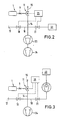
- Fig. 2 shows the functional diagram of a main current leak detector.
- the connection 17 is connected to the test gas detector 22, preferably a mass spectrometer, via the main line 18 with the valves 19 and 21.
- the device according to the invention with the line 14 and a vacuum pump set are connected between the two valves 19 and 21.
- the vacuum pump set consists of the high vacuum pump 23, for example a diffusion pump, and the fore vacuum pump 24.
- control unit 25 with a control unit is also designated, which is connected via control lines to the 3/2-way valve 11 and to the valves 19 and 21.
- the valves 19 and 21 are opened, so that test gas which may be present in the test specimen may leak test gas to the detector 22.
- the test leak 1 is connected via the 3/2-way valve 11 to the line 15 leading to the atmosphere.
- the switch from leak detection mode to test mode is carried out in such a way that the valve 19 is closed and the 3/2-way valve is switched such that the test leak 1 is connected to the detector 22 via the line 14 and the main line 18. If the valve 11 does not switch sufficiently quickly, the valve 21 can be closed before switching over to test mode and can be kept closed for a short time after switching over, so that the air swallow, which may endanger the detector 22, can be sucked off by the pumps 23 and 24. Immediately afterwards, the leak rate of the test leak 1 is available in an unadulterated manner.
- Fig. 3 shows the functional diagram of a countercurrent leak detector.
- the high vacuum pump 23, a turbomolecular vacuum pump, lies in the line 18 and is immediately upstream of the mass spectrometer detector 22.
- the valves 19 and 21 are open again.
- the 3/2-way valve connects the outlet of test leak 1 with the atmosphere. Switching to test mode takes place in the manner described for FIG. 2.
Landscapes
- Physics & Mathematics (AREA)
- General Physics & Mathematics (AREA)
- Examining Or Testing Airtightness (AREA)
Applications Claiming Priority (2)
| Application Number | Priority Date | Filing Date | Title |
|---|---|---|---|
| DE3613694 | 1986-04-23 | ||
| DE19863613694 DE3613694A1 (de) | 1986-04-23 | 1986-04-23 | Vorrichtung zur kalibrierung des detektors eines lecksuchgeraetes |
Publications (3)
| Publication Number | Publication Date |
|---|---|
| EP0242684A2 true EP0242684A2 (fr) | 1987-10-28 |
| EP0242684A3 EP0242684A3 (en) | 1989-12-13 |
| EP0242684B1 EP0242684B1 (fr) | 1992-06-03 |
Family
ID=6299315
Family Applications (1)
| Application Number | Title | Priority Date | Filing Date |
|---|---|---|---|
| EP87105048A Expired - Lifetime EP0242684B1 (fr) | 1986-04-23 | 1987-04-04 | Appareil de détection de fuites avec détecteur et fuite de test |
Country Status (4)
| Country | Link |
|---|---|
| US (1) | US4794784A (fr) |
| EP (1) | EP0242684B1 (fr) |
| JP (1) | JP2635587B2 (fr) |
| DE (2) | DE3613694A1 (fr) |
Cited By (5)
| Publication number | Priority date | Publication date | Assignee | Title |
|---|---|---|---|---|
| EP0352371A3 (en) * | 1988-07-27 | 1990-05-30 | Varian S.P.A. | Improved detector for helium leaks |
| WO1996019721A1 (fr) * | 1994-12-22 | 1996-06-27 | Leybold Vakuum Gmbh | Detecteur de fuites renifleur a contre-courant |
| DE10124260A1 (de) * | 2001-05-18 | 2002-12-05 | Boehringer Ingelheim Pharma | System zur Überprüfung von Systemen, die ihrerseits zur Überprüfung der Dichtigkeit eines Hohlkörpers dienen |
| US9933325B2 (en) | 2013-08-20 | 2018-04-03 | Inficon Gmbh | Pico test leak |
| CN116625593A (zh) * | 2023-07-25 | 2023-08-22 | 爱发科东方检测技术(成都)有限公司 | 一种锂电池检漏用模拟漏孔及其使用方法 |
Families Citing this family (18)
| Publication number | Priority date | Publication date | Assignee | Title |
|---|---|---|---|---|
| US5013006A (en) * | 1989-07-24 | 1991-05-07 | Cosmo Instruments Co., Ltd. | Micro-leakage regulating valve |
| US4991426A (en) * | 1989-08-22 | 1991-02-12 | Oakland Engineering, Inc. | Calibration of air leak detection apparatus |
| DE4037524A1 (de) * | 1990-11-26 | 1992-05-27 | Leybold Ag | Lecksuchgeraet |
| US5546789A (en) * | 1992-08-03 | 1996-08-20 | Intertech Development Company | Leakage detection system |
| US5349846A (en) * | 1993-01-25 | 1994-09-27 | Hughes Aircraft Company | Portable leak/flow test equipment for night vision equipment |
| US6082184A (en) * | 1997-05-27 | 2000-07-04 | Martin Lehmann | Method for leak testing and leak testing apparatus |
| DE19906941A1 (de) * | 1999-02-19 | 2000-08-24 | Leybold Vakuum Gmbh | Testleck |
| US6584828B2 (en) | 1999-12-17 | 2003-07-01 | Atc, Inc. | Method and apparatus of nondestructive testing a sealed product for leaks |
| DE10358716A1 (de) * | 2003-12-10 | 2005-07-14 | Siemens Ag | Verfahren sowie Vorrichtung zur Dichteprüfung eines gasgefüllten Behälters |
| US7334456B2 (en) * | 2004-05-11 | 2008-02-26 | Franklin Fueling Systems, Inc. | Method and apparatus for continuously monitoring interstitial regions in gasoline storage facilities and pipelines |
| US7051579B2 (en) * | 2004-05-11 | 2006-05-30 | Franklin Fueling Systems, Inc. | Method and apparatus for continuously monitoring interstitial regions in gasoline storage facilities and pipelines |
| US7624624B2 (en) * | 2007-07-05 | 2009-12-01 | Chrysler Group Llc | Pump assembly and method for leak detection of fluid system |
| FR2988403B1 (fr) * | 2012-03-20 | 2014-05-09 | Riber | Appareil de depot sous vide a cellules a vanne comportant un dispositif de detection de fuite et procede de detection d'une fuite dans un appareil de depot sous vide |
| DE102012220108A1 (de) * | 2012-11-05 | 2014-05-22 | Inficon Gmbh | Verfahren zur Prüfung einer Dichtheitsprüfanlage |
| JP6091017B2 (ja) * | 2012-11-21 | 2017-03-08 | 国立研究開発法人産業技術総合研究所 | 参照リーク発生装置およびそれを用いた超微小リーク試験装置 |
| CN103884718B (zh) * | 2014-04-16 | 2017-12-01 | 中国石油化工股份有限公司 | 一种用于检测光学气体成像设备的试验装置 |
| DE102023002983B3 (de) | 2023-07-21 | 2024-08-08 | Mercedes-Benz Group AG | Mobile Vorrichtung zur Kalibrierung einer prüfgasbasierten Dichtheitsprüfanordnung mittels eines Testlecks und Verfahren zur Kalibrierung einer prüfgasbasierten Dichtheitsprüfanordnung |
| CN116773233B (zh) * | 2023-08-01 | 2026-03-20 | 中国计量科学研究院 | 一种血压模拟器校准装置 |
Family Cites Families (9)
| Publication number | Priority date | Publication date | Assignee | Title |
|---|---|---|---|---|
| CH364152A (de) * | 1957-12-12 | 1962-08-31 | Concordia Masch & Elekt | Kolbenschieber-Steuervorrichtung für gasförmige und flüssige Medien |
| DE1923193A1 (de) * | 1969-05-07 | 1970-11-19 | Establishment Bornex | Quarzsandbauplatte |
| DE2427905A1 (de) * | 1974-06-10 | 1976-01-02 | Hoke Inc | Schieberanschlusskopf |
| US4328700A (en) * | 1977-03-14 | 1982-05-11 | Chevron Research Company | Leak detection method and apparatus |
| DD144821A1 (de) * | 1979-07-12 | 1980-11-05 | Hartmut Bareinz | Verfahren und einrichtung zur nachbildung von lecks |
| US4343176A (en) * | 1980-11-12 | 1982-08-10 | The United States Of America As Represented By The United States Department Of Energy | Long-life leak standard assembly |
| DE3147030C2 (de) * | 1981-11-27 | 1985-08-01 | Festo-Maschinenfabrik Gottlieb Stoll, 7300 Esslingen | Magnetventileinheit |
| EP0110004B1 (fr) * | 1982-11-26 | 1987-08-12 | Leybold Aktiengesellschaft | Fuite d'étalonnage |
| DE3243752A1 (de) * | 1982-11-26 | 1984-05-30 | Leybold-Heraeus GmbH, 5000 Köln | Testleck |
-
1986
- 1986-04-23 DE DE19863613694 patent/DE3613694A1/de not_active Withdrawn
-
1987
- 1987-04-04 EP EP87105048A patent/EP0242684B1/fr not_active Expired - Lifetime
- 1987-04-04 DE DE8787105048T patent/DE3779482D1/de not_active Expired - Lifetime
- 1987-04-21 JP JP62096369A patent/JP2635587B2/ja not_active Expired - Lifetime
- 1987-04-23 US US07/041,416 patent/US4794784A/en not_active Expired - Lifetime
Cited By (7)
| Publication number | Priority date | Publication date | Assignee | Title |
|---|---|---|---|---|
| EP0352371A3 (en) * | 1988-07-27 | 1990-05-30 | Varian S.P.A. | Improved detector for helium leaks |
| WO1996019721A1 (fr) * | 1994-12-22 | 1996-06-27 | Leybold Vakuum Gmbh | Detecteur de fuites renifleur a contre-courant |
| US5907092A (en) * | 1994-12-22 | 1999-05-25 | Leybold Aktiengesellschaft | Countercurrent sniffing leak detector |
| DE10124260A1 (de) * | 2001-05-18 | 2002-12-05 | Boehringer Ingelheim Pharma | System zur Überprüfung von Systemen, die ihrerseits zur Überprüfung der Dichtigkeit eines Hohlkörpers dienen |
| US9933325B2 (en) | 2013-08-20 | 2018-04-03 | Inficon Gmbh | Pico test leak |
| EP3036518B1 (fr) * | 2013-08-20 | 2018-10-10 | Inficon GmbH | Pico-fuite étalon |
| CN116625593A (zh) * | 2023-07-25 | 2023-08-22 | 爱发科东方检测技术(成都)有限公司 | 一种锂电池检漏用模拟漏孔及其使用方法 |
Also Published As
| Publication number | Publication date |
|---|---|
| DE3613694A1 (de) | 1987-10-29 |
| EP0242684B1 (fr) | 1992-06-03 |
| EP0242684A3 (en) | 1989-12-13 |
| JP2635587B2 (ja) | 1997-07-30 |
| DE3779482D1 (de) | 1992-07-09 |
| JPS62259033A (ja) | 1987-11-11 |
| US4794784A (en) | 1989-01-03 |
Similar Documents
| Publication | Publication Date | Title |
|---|---|---|
| EP0242684B1 (fr) | Appareil de détection de fuites avec détecteur et fuite de test | |
| EP0615615B1 (fr) | Detecteur de fuites pour installations a vide, et procede de recherche de fuites dans des installations a vide | |
| DE19523430C2 (de) | Lecknachweisgerät, das eine Verbund-Turbomolekularpumpe benutzt | |
| EP2076751B1 (fr) | Detecteur renifleur de fuites | |
| EP0793802B1 (fr) | Dispositif de detection de fuites pourvu de pompes a vide et procede permettant son fonctionnement | |
| DE102010033373A1 (de) | Lecksuchgerät | |
| DE1937271B2 (de) | Anordnung zur Lecksuche | |
| EP0432305A1 (fr) | Procédé et dispositif de contrôle d'étanchéité | |
| DE102007043382A1 (de) | Schnüffellecksucher | |
| DE10156205A1 (de) | Testgaslecksuchgerät | |
| DE69007930T2 (de) | System zur Aufspürung von Undichtigkeit unter Verwendung von Trägergas. | |
| DE69103499T2 (de) | Hochleistungsleckdetektor mit drei Molekularfiltern. | |
| EP0834061A1 (fr) | Appareil de detection de fuite dote d'une pompe a previde | |
| DE10324596A1 (de) | Lecksuchgerät | |
| DE1211003B (de) | Einlasssystem fuer Massenspektrometer mit Probezufuehrung ueber eine Kapillare mit Drosselstelle und ein Einlassventil, mit Mitteln zur Vermeidung eines Druckstosses beim OEffnen des Ventils | |
| DE102023209077A1 (de) | Verfahren und Vorrichtung zum Bestimmen einer Position einer Leckage an einem Bauteil | |
| EP4204805B1 (fr) | Appareil et procédé de dégazage d'un navire de dégazage, et système de test correspondant pour analyse de gaz | |
| DE69515269T2 (de) | Leckdetektor | |
| DE19938392A1 (de) | Einlaßsystem für Ionenmobilitätsspektrometer | |
| EP0890100B1 (fr) | Dispositif pour le raccordement d'une entree basse pression dans un appareil d'analyse de gaz | |
| EP0852711B1 (fr) | Dispositif permettant de determiner des profils de concentration de substances liquides ou gazeuses le long d'une section | |
| DE9405028U1 (de) | Testgas-Lecksuchgerät | |
| DE3308555C1 (de) | Vorrichtung zur automatischen Messung der Leckrate eines Behälters | |
| DE1600509B1 (de) | Verfahren und Vorrichtung zur Pruefung der Dichtigkeit von zwei in Serie geschalteten Abschlussventilen in einer Gasleitung | |
| DE4326267A1 (de) | Lecksuchgerät |
Legal Events
| Date | Code | Title | Description |
|---|---|---|---|
| PUAI | Public reference made under article 153(3) epc to a published international application that has entered the european phase |
Free format text: ORIGINAL CODE: 0009012 |
|
| AK | Designated contracting states |
Kind code of ref document: A2 Designated state(s): DE FR GB |
|
| RAP1 | Party data changed (applicant data changed or rights of an application transferred) |
Owner name: LEYBOLD AKTIENGESELLSCHAFT |
|
| PUAL | Search report despatched |
Free format text: ORIGINAL CODE: 0009013 |
|
| AK | Designated contracting states |
Kind code of ref document: A3 Designated state(s): DE FR GB |
|
| 17P | Request for examination filed |
Effective date: 19900201 |
|
| 17Q | First examination report despatched |
Effective date: 19910211 |
|
| GRAA | (expected) grant |
Free format text: ORIGINAL CODE: 0009210 |
|
| AK | Designated contracting states |
Kind code of ref document: B1 Designated state(s): DE FR GB |
|
| GBT | Gb: translation of ep patent filed (gb section 77(6)(a)/1977) | ||
| REF | Corresponds to: |
Ref document number: 3779482 Country of ref document: DE Date of ref document: 19920709 |
|
| ET | Fr: translation filed | ||
| PLBE | No opposition filed within time limit |
Free format text: ORIGINAL CODE: 0009261 |
|
| STAA | Information on the status of an ep patent application or granted ep patent |
Free format text: STATUS: NO OPPOSITION FILED WITHIN TIME LIMIT |
|
| 26N | No opposition filed | ||
| REG | Reference to a national code |
Ref country code: GB Ref legal event code: IF02 |
|
| PGFP | Annual fee paid to national office [announced via postgrant information from national office to epo] |
Ref country code: FR Payment date: 20060313 Year of fee payment: 20 |
|
| PGFP | Annual fee paid to national office [announced via postgrant information from national office to epo] |
Ref country code: GB Payment date: 20060316 Year of fee payment: 20 |
|
| PGFP | Annual fee paid to national office [announced via postgrant information from national office to epo] |
Ref country code: DE Payment date: 20060317 Year of fee payment: 20 |
|
| REG | Reference to a national code |
Ref country code: GB Ref legal event code: PE20 |
|
| PG25 | Lapsed in a contracting state [announced via postgrant information from national office to epo] |
Ref country code: GB Free format text: LAPSE BECAUSE OF EXPIRATION OF PROTECTION Effective date: 20070403 |