EP0242684A2 - Leak-detecting apparatus with detector and test leak - Google Patents
Leak-detecting apparatus with detector and test leak Download PDFInfo
- Publication number
- EP0242684A2 EP0242684A2 EP87105048A EP87105048A EP0242684A2 EP 0242684 A2 EP0242684 A2 EP 0242684A2 EP 87105048 A EP87105048 A EP 87105048A EP 87105048 A EP87105048 A EP 87105048A EP 0242684 A2 EP0242684 A2 EP 0242684A2
- Authority
- EP
- European Patent Office
- Prior art keywords
- leak
- test
- detector
- valve
- way valve
- Prior art date
- Legal status (The legal status is an assumption and is not a legal conclusion. Google has not performed a legal analysis and makes no representation as to the accuracy of the status listed.)
- Granted
Links
Images

Classifications
-
- G—PHYSICS
- G01—MEASURING; TESTING
- G01M—TESTING STATIC OR DYNAMIC BALANCE OF MACHINES OR STRUCTURES; TESTING OF STRUCTURES OR APPARATUS, NOT OTHERWISE PROVIDED FOR
- G01M3/00—Investigating fluid-tightness of structures
- G01M3/02—Investigating fluid-tightness of structures by using fluid or vacuum
- G01M3/04—Investigating fluid-tightness of structures by using fluid or vacuum by detecting the presence of fluid at the leakage point
- G01M3/20—Investigating fluid-tightness of structures by using fluid or vacuum by detecting the presence of fluid at the leakage point using special tracer materials, e.g. dye, fluorescent material, radioactive material
- G01M3/207—Investigating fluid-tightness of structures by using fluid or vacuum by detecting the presence of fluid at the leakage point using special tracer materials, e.g. dye, fluorescent material, radioactive material calibration arrangements
Definitions
- the invention relates to a device for calibrating the detector of a leak detector using a test leak and with a valve located between the test leak and the detector.
- test leaks working with helium as test gas are able to detect helium leak rates of up to less than 10 ⁇ 10 mbar l / sec. With the help of test leaks - preferably with their own gas supply - such leak detectors are checked and / or compared. Test leaks are practically a leak with a known leak rate. A general requirement for test leaks is therefore that they deliver stable test gas flows for as long as possible. Furthermore, the test gas flow should be available as quickly as possible after the start of a calibration process.
- the calibration of a helium leak detector is usually carried out by comparing the known leak rate of the test leak with the display of the leak detector.
- a correction factor is either formed from the two values or the display is adjusted to the correct value using a suitable setting element.
- Test leaks can essentially be divided into two groups.
- the first group includes test leaks with leak rates greater than 10 ⁇ 6 mbar l / sec. These have a relatively high test gas consumption, which - if the test gas continuously flows out - would lead to pressure changes relatively early. With a change in pressure, the leak rate of the test leak also changes, so that it is no longer used for calibration purposes can be used. It is therefore known to equip test leaks of this type, that is to say for leak rates greater than 10 mbar l / sec, with a shut-off valve (DE-OS 32 43 752). The shut-off valve is closed when the test leak is not in use.
- the second group includes test leaks that deliver leak rates of less than 10 ⁇ 6 mbar l / sec and are therefore suitable for the calibration of highly sensitive leak detectors. Due to the very low leakage rates, such a test leak delivers an almost constant gas flow over many years, even if it is not sealed, even with a relatively small gas supply. Test leaks of this type therefore often do not have a shut-off valve. However, if there is a need to interrupt the test gas flow, a test leak of this type must also be equipped with a shut-off valve. This need exists e.g. B. in a test leak installed in a highly sensitive leak detector, in order to be able to trigger a calibration at any time even when a test specimen is connected or in automatic processes.
- shut-off valves When using shut-off valves for test leaks, the following phenomena are unavoidable: The shut-off valve must remain closed for often very long periods of time that lie between two calibration processes. When the valve is closed, test gas collects in the space in front of the closure element (dead space). This accumulation leads to the fact that, after opening the shut-off valve, a "test gas swallow" is first registered, which can be so large and its concentration so high that the risk of contamination and / or overloading of registration devices, e.g. B. the test gas sensitive mass spectrometer detector. In addition, the closure element is exposed to the full test gas pressure (a few bar) when the valve is closed. As a result, test gas accumulates in the closure element, in particular in the sealing materials.
- the valve is opened for the purpose of initiating a calibration process, the penetrated gas particles emerge again and falsify the actual leakage current of the test leak (drift) for a relatively long time.
- the closure element is a membrane made of rubber or plastic, then the described drift phenomena occur to a particularly high degree. In addition, permeation through the membrane is unavoidable when the valve is closed - i.e. during leak detection. If the test leak is installed in a leak detector, the particles passing through the membrane reach the test gas sensitive detector.
- test leak according to DE-OS 32 43 752 which belongs to the first group of test leaks, that is to say leak rates greater than 10 ⁇ 6 mbar l / sec, there is virtually no more dead space in front of the closure piece of the shut-off valve.
- the disadvantageous phenomena “test gas swallowing”, “drift” and “permeation” are suppressed to such an extent that they are negligible compared to the target leak rate and therefore do not falsify the calibration.
- the branch line opens into the main line, which is connected to the test object to be checked for leaks and is also equipped with a valve.
- the valve in the branch line is closed while the valve in the main line is open.
- the high test gas concentration leading to an undesirable "test gas swallow” would entail the risk of contamination and / or overloading of the mass spectrometer detector. In addition, the drift phenomena already described would occur.
- the valve to the pump is closed and the valve to the leak detector is opened.
- the present invention has for its object to provide a device for calibrating a leak detector, in which an undesirable test gas swallow and drift phenomena are avoided without the effort of using a separate vacuum pump.
- the valve located between the test leak and the detector is a fast-switching 3/2-way valve which connects the outlet of the test leak either to the atmosphere (leak detection mode) or to the input of the detector to be calibrated (test mode).
- the outlet of the test leak and the 3/2-way valve are preferably as close as possible to one another.
- test leak and the valve are not close to each other and / or the 3/2-way valve does not switch quickly enough, then a further valve is expediently provided in front of the detector, which protects the detector from a brief, harmful pressure increase.
- the time it takes to pump out the "air swallow” is no more than a few seconds.
- the target leak rate of the test leak is available immediately thereafter. There are no drift phenomena or permeation.
- the particular advantage of the device according to the invention is that it is for an automated, for. B. microprocessor-controlled operation is particularly suitable.
- the test leak can be opened and closed electrically using the 3/2-way valve.
- the test leak can be separated from the detector for any length of time without deviations from the target leak rate occurring when opening.
- the device according to the invention is considerably simpler since a separate vacuum pump is no longer required.
- the entire arrangement is compact and light and can be installed in a portable leak detector without impairment. Older leak detectors can also be retrofitted with the device according to the invention.
- test leak 1 is only partially shown. It includes the housing 2 with the helium supply 3.
- the housing 2 is closed with a cover 4 which has a channel 5 for the helium flowing out of the helium supply 3.
- the element determining the leak rate is designated by 6.
- a cylindrical glass body 7 with a central capillary 8 is shown as an example.
- a diffusion finger, a membrane or the like can also be present as the leak-determining element.
- the channel 5 in the cover 4 opens directly into the housing 9 of the 3/2-way valve 11.
- the valve plunger 12 shown in an intermediate position can be switched over as quickly as possible between two end positions. In its one position (leak detection mode) it lies against the seat 13 and thus closes the channel 14 leading to the leak detector.
- the channel 15 leading to the atmosphere with the seat 16 is open.
- the helium constantly escaping from the constriction 6 flows into the atmosphere. As a result, high test gas pressures or concentrations cannot occur within the valve housing 9.
- the plunger 12 In its second position, the plunger 12 lies against the seat 16 and thus closes the channel 15 leading to the atmosphere. Immediately thereafter, the helium emerging from the constriction 6 with a known leak rate is available for calibration purposes. If the interior of the housing 9 is kept sufficiently small and the changeover movement of the plunger 12 is sufficiently rapid, then an air swallow which endangers the detector to be calibrated does not occur.
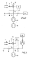
- Fig. 2 shows the functional diagram of a main current leak detector.
- the connection 17 is connected to the test gas detector 22, preferably a mass spectrometer, via the main line 18 with the valves 19 and 21.
- the device according to the invention with the line 14 and a vacuum pump set are connected between the two valves 19 and 21.
- the vacuum pump set consists of the high vacuum pump 23, for example a diffusion pump, and the fore vacuum pump 24.
- control unit 25 with a control unit is also designated, which is connected via control lines to the 3/2-way valve 11 and to the valves 19 and 21.
- the valves 19 and 21 are opened, so that test gas which may be present in the test specimen may leak test gas to the detector 22.
- the test leak 1 is connected via the 3/2-way valve 11 to the line 15 leading to the atmosphere.
- the switch from leak detection mode to test mode is carried out in such a way that the valve 19 is closed and the 3/2-way valve is switched such that the test leak 1 is connected to the detector 22 via the line 14 and the main line 18. If the valve 11 does not switch sufficiently quickly, the valve 21 can be closed before switching over to test mode and can be kept closed for a short time after switching over, so that the air swallow, which may endanger the detector 22, can be sucked off by the pumps 23 and 24. Immediately afterwards, the leak rate of the test leak 1 is available in an unadulterated manner.
- Fig. 3 shows the functional diagram of a countercurrent leak detector.
- the high vacuum pump 23, a turbomolecular vacuum pump, lies in the line 18 and is immediately upstream of the mass spectrometer detector 22.
- the valves 19 and 21 are open again.
- the 3/2-way valve connects the outlet of test leak 1 with the atmosphere. Switching to test mode takes place in the manner described for FIG. 2.
Landscapes
- Physics & Mathematics (AREA)
- General Physics & Mathematics (AREA)
- Examining Or Testing Airtightness (AREA)
Abstract
Die Erfindung bezieht sich auf eine Vorrichtung zur Kalibrierung des Detektors eines Lecksuchgerätes mit Hilfe eines Testlecks (1); um bei hochempfindlichen Lecksuchgeräten Testlecks mit Leckraten kleiner 10⁻⁶ mbar l/sec einsetzen zu können, wird vorgeschlagen, zwischen dem Testleck (1) und dem Detektor (22) ein schnell schaltendes 3/2-Wegeventil (11) vorzusehen, das den Auslaß des Testlecks (1) entweder mit der Atmosphäre (Lecksuchbetrieb) oder mit dem Eingang des zu kalibrierenden Detektors (Testbetrieb) verbindet. Unmittelbar nach dem Umschalten des 3/2-Wegeventils auf den Testbetrieb steht der Leckstrom unverfälscht zur Verfügung. 
Description
Die Erfindung bezieht sich auf eine Vorrichtung zur Kalibrierung des Detektors eines Lecksuchgerätes mit Hilfe eines Testlecks und mit einem zwischen dem Testleck und dem Detektor befindlichen Ventil.The invention relates to a device for calibrating the detector of a leak detector using a test leak and with a valve located between the test leak and the detector.
Moderne, mit Helium als Testgas arbeitende Leckdetektoren sind in der Lage, Helium-Leckraten bis zu weniger als 10⁻¹⁰ mbar l/sec nachzuweisen. Mit Hilfe von Testlecks - vorzugsweise mit eigenem Gasvorrat - erfolgt die Kontrolle und/oder der Abgleich derartiger Lecksuchgeräte. Testlecks stellen praktisch ein Leck mit einer bekannten Leckrate dar. Eine generelle Forderung an Testlecks ist deshalb, daß sie über möglichst lange Zeiten stabile Testgasströme liefern. Weiterhin soll der Testgasstrom möglichst schnell nach dem Beginn eines Kalibriervorganges unverfälscht zur Verfügung stehen.Modern leak detectors working with helium as test gas are able to detect helium leak rates of up to less than 10⁻¹⁰ mbar l / sec. With the help of test leaks - preferably with their own gas supply - such leak detectors are checked and / or compared. Test leaks are practically a leak with a known leak rate. A general requirement for test leaks is therefore that they deliver stable test gas flows for as long as possible. Furthermore, the test gas flow should be available as quickly as possible after the start of a calibration process.
Die Kalibrierung eines Heliumlecksuchgerätes erfolgt üblicherweise dadurch, daß die bekannte Leckrate des Testlecks mit der Anzeige des Lecksuchgerätes verglichen wird. Aus den beiden Werten wird entweder ein Korrekturfaktor gebildet oder die Anzeige mit einem geeigneten Einstellelement auf den richtigen Wert abgeglichen.The calibration of a helium leak detector is usually carried out by comparing the known leak rate of the test leak with the display of the leak detector. A correction factor is either formed from the two values or the display is adjusted to the correct value using a suitable setting element.
Testlecks können im wesentlichen in zwei Gruppen unterteilt werden. Zur ersten Gruppe gehören Testlecks mit Leckraten größer 10⁻⁶ mbar l/sec. Diese haben einen relativ hohen Testgasverbrauch, was - bei ständig ausströmendem Testgas - relativ früh zu Druckänderungen führen würde. Mit einer Druckänderung ändert sich auch die Leckrate des Testlecks, so daß es nicht mehr zu Kalibrierzwecken verwendet werden kann. Es ist deshalb bekannt, Testlecks dieses Typs, also für Leckraten größer 10⁻⁶ mbar l/sec, mit einem Absperrventil auszurüsten (DE-OS 32 43 752). Bei Nichtgebrauch des Testlecks ist das Absperrventil verschlossen.Test leaks can essentially be divided into two groups. The first group includes test leaks with leak rates greater than 10⁻⁶ mbar l / sec. These have a relatively high test gas consumption, which - if the test gas continuously flows out - would lead to pressure changes relatively early. With a change in pressure, the leak rate of the test leak also changes, so that it is no longer used for calibration purposes can be used. It is therefore known to equip test leaks of this type, that is to say for leak rates greater than 10 mbar l / sec, with a shut-off valve (DE-OS 32 43 752). The shut-off valve is closed when the test leak is not in use.
Zur zweiten Gruppe gehören Testlecks, die Leckraten kleiner 10⁻⁶ mbar l/sec liefern und damit zur Kalibrierung hochempfindlicher Lecksuchgeräte geeignet sind. Wegen der sehr kleinen Leckraten liefert ein solches Testleck selbst bei relativ kleinem Gasvorrat über Jahre hinweg einen annähernd konstanten Gasstrom, auch wenn es nicht verschlossen ist. Testlecks dieses Typs weisen deshalb häufig kein Absperrventil auf. Besteht jedoch die Notwendigkeit, den Testgasstrom zu unterbrechen, dann muß auch ein Testleck dieses Typs mit einem Absperrventil ausgerüstet sein. Diese Notwendigkeit besteht z. B. bei einem in ein hochempfindliches Lecksuchgerät eingebautes Testleck, um auch bei angeschlossenem Prüfling oder in automatischen Abläufen jederzeit eine Kalibrierung auslösen zu können.The second group includes test leaks that deliver leak rates of less than 10⁻⁶ mbar l / sec and are therefore suitable for the calibration of highly sensitive leak detectors. Due to the very low leakage rates, such a test leak delivers an almost constant gas flow over many years, even if it is not sealed, even with a relatively small gas supply. Test leaks of this type therefore often do not have a shut-off valve. However, if there is a need to interrupt the test gas flow, a test leak of this type must also be equipped with a shut-off valve. This need exists e.g. B. in a test leak installed in a highly sensitive leak detector, in order to be able to trigger a calibration at any time even when a test specimen is connected or in automatic processes.
Bei der Verwendung von Absperrventilen bei Testlecks sind die folgenden Erscheinungen unvermeidbar: Das Absperrventil muß für häufig sehr lange Zeiträume, die zwischen zwei Kalibriervorgängen liegen, verschlossen bleiben. Im Schließzustand des Ventils sammelt sich in dem Raum vor dem Verschlußelement (Totraum) Testgas an. Diese Ansammlung führt dazu, daß nach dem Öffnen des Absperrventils zunächst ein "Testgasschluck" registriert wird, der so groß und dessen Konzentration so hoch sein kann, daß die Gefahr einer Verseuchung und/oder Übersteuerung von Registriergeräten, z. B. des testgasempfindlichen Massenspektrometer-Detektors, besteht. Darüber hinaus ist das Verschlußelement während des Schließzustandes des Ventils dem vollen Testgasdruck (einige bar) ausgesetzt. Dadurch reichert sich Testgas in dem Verschlußelement, insbesondere in den Dichtwerkstoffen, an. Wird das Ventil zum Zwecke der Einleitung eines Kalibriervorganges geöffnet, dann treten die eingedrungenen Gasteilchen wieder aus und verfälschen für eine relativ lange Zeit den eigentlichen Leckstrom des Testlecks (Drift). Ist das Verschlußelement eine aus Gummi oder Kunststoff bestehende Membran, dann treten die beschriebenen Drifterscheinungen in besonders hohem Maße auf. Darüber hinaus ist bei geschlossenem Ventil - also während des Lecksuchbetriebs - eine Permeation durch die Membran unvermeidbar. Ist das Testleck in einen Lecksucher eingebaut, dann gelangen die durch die Membran hindurchtretenden Teilchen zum testgasempfindlichen Detektor.When using shut-off valves for test leaks, the following phenomena are unavoidable: The shut-off valve must remain closed for often very long periods of time that lie between two calibration processes. When the valve is closed, test gas collects in the space in front of the closure element (dead space). This accumulation leads to the fact that, after opening the shut-off valve, a "test gas swallow" is first registered, which can be so large and its concentration so high that the risk of contamination and / or overloading of registration devices, e.g. B. the test gas sensitive mass spectrometer detector. In addition, the closure element is exposed to the full test gas pressure (a few bar) when the valve is closed. As a result, test gas accumulates in the closure element, in particular in the sealing materials. If the valve is opened for the purpose of initiating a calibration process, the penetrated gas particles emerge again and falsify the actual leakage current of the test leak (drift) for a relatively long time. If the closure element is a membrane made of rubber or plastic, then the described drift phenomena occur to a particularly high degree. In addition, permeation through the membrane is unavoidable when the valve is closed - i.e. during leak detection. If the test leak is installed in a leak detector, the particles passing through the membrane reach the test gas sensitive detector.
Bei dem Testleck nach der DE-OS 32 43 752, das zur ersten Gruppe der Testlecks gehört, also Leckraten größer 10⁻⁶ mbar l/sec liefert, ist ein Totraum vor dem Verschlußstück des Absperrventils nahezu nicht mehr vorhanden. Die nachteiligen Erscheinungen "Testgasschluck", "Drift" und "Permeation" sind dadurch so weit unterdrückt, daß sie vernachlässigbar sind gegenüber der Soll-Leckrate und deshalb die Kalibrierung nicht verfälschen.In the test leak according to DE-OS 32 43 752, which belongs to the first group of test leaks, that is to say leak rates greater than 10⁻⁶ mbar l / sec, there is virtually no more dead space in front of the closure piece of the shut-off valve. The disadvantageous phenomena "test gas swallowing", "drift" and "permeation" are suppressed to such an extent that they are negligible compared to the target leak rate and therefore do not falsify the calibration.
Für ein Testleck der zweiten Gruppe, also mit Leckraten kleiner 10⁻⁶ mbar l/sec, ist das Absperrventil nach der DE-OS 32 43 752 nicht mehr einsetzbar, weil die durch die nachteiligen Erscheinungen "Testgasschluck", "Drift" und "Permeation" auftretenden Gasströme im Vergleich zu den Soll-Leckraten nicht mehr vernachlässigbar sind. Um Verfälschungen dieser Art zu vermeiden, ist es bekannt, als absperrbares Testleck für kleine Leckraten ein sogenanntes "gepumptes" Testleck zu verwenden. Der Auslaß eines solchen Testlecks steht über eine Zweigleitung und ein darin angeordnetes Ventil ständig mit dem Eingang des Lecksuchgerätes, in das es eingebaut ist, in Verbindung. Die Zweigleitung mündet in die Hauptleitung, die mit dem auf Lecks zu untersuchenden Prüfling verbunden wird und ebenfalls mit einem Ventil ausgerüstet ist. Während des Normalbetriebs ist das Ventil in der Zweigleitung geschlossen, während das Ventil in der Hauptleitung offen ist. Bei einer Einrichtung dieser Art ist es erforderlich, an den Raum zwischen dem Auslaß des Testlecks und dem Ventil in der Zweigleitung über ein weiteres Ventil eine gesonderte Vakuumpumpe anzuschließen, mit der das ständig aus dem Testleck austretende Testgas abgesaugt wird. Ohne Evakuierung würde sich dieser Raum mit Testgas in hoher Konzentration füllen und damit nicht unmittelbar mit dem zu kalibrierenden Detektor verbunden werden können. Mit der hohen, zu einem unerwünschten "Testgasschluck" führenden Testgaskonzentration wäre die Gefahr einer Verseuchung und/oder Übersteuerung des Massenspektrometerdetektors verbunden. Außerdem würden die bereits beschriebenen Drifterscheinungen eintreten. Zur Kalibrierung wird das Ventil zur Pumpe geschlossen und das Ventil zum Lecksucher hin geöffnet.For a test leak of the second group, ie with leak rates of less than 10⁻⁶ mbar l / sec, the shut-off valve according to DE-OS 32 43 752 can no longer be used, because of the disadvantageous phenomena "test gas swallowing", "drift" and "permeation "occurring gas flows are no longer negligible compared to the target leak rates. In order to avoid falsifications of this type, it is known to use a so-called "pumped" test leak as a test leak that can be shut off for small leak rates. The outlet of such a test leak is constantly connected to the inlet of the via a branch line and a valve arranged therein Leak detector in which it is installed. The branch line opens into the main line, which is connected to the test object to be checked for leaks and is also equipped with a valve. During normal operation, the valve in the branch line is closed while the valve in the main line is open. In a device of this type, it is necessary to connect a separate vacuum pump to the space between the outlet of the test leak and the valve in the branch line via a further valve, by means of which the test gas which constantly emerges from the test leak is sucked off. Without evacuation, this space would be filled with test gas in high concentration and could not be connected directly to the detector to be calibrated. The high test gas concentration leading to an undesirable "test gas swallow" would entail the risk of contamination and / or overloading of the mass spectrometer detector. In addition, the drift phenomena already described would occur. For calibration, the valve to the pump is closed and the valve to the leak detector is opened.
Der Aufwand für ein "gepumptes" Testleck ist hoch, zumal eine separate Vakuumpumpe dafür erforderlich ist. Üblicherweise wird man die der Vorevakuierung dienende Hilfspumpe dazu verwenden. Die der Evakuierung des Massenspektrometers dienenden Vakuumpumpen können dazu nicht verwendet werden, da das abgepumpte Helium durch diese Pumpen zurückdiffundieren und die Lecksuche verfälschen würde. Tragbare Lecksucher können wegen des Gewichtes der separaten (zusätzlichen) Vakuumpumpe nicht mit einem "gepumpten" Testleck ausgerüstet werden. Nur in größeren Anlagen, bei denen entweder Kosten und Gewichtsprobleme nicht im Vordergrund stehen oder in denen sich weitere Vakuumpumpen befinden, die das Abpumpen des Testlecks mitübernehmen können, finden "gepumpte" Testlecks Anwendung.The effort for a "pumped" test leak is high, especially since a separate vacuum pump is required. Usually the auxiliary pump used for the pre-evacuation will be used. The vacuum pumps used to evacuate the mass spectrometer cannot be used for this, since the pumped helium would diffuse back through these pumps and falsify the search for leaks. Portable leak detectors cannot be equipped with a "pumped" test leak due to the weight of the separate (additional) vacuum pump. "Pumped" test leaks are only used in larger systems, in which either costs and weight problems are not the main focus or in which there are further vacuum pumps that can take over the pumping of the test leak.
Der vorliegenden Erfindung liegt die Aufgabe zugrunde, eine Vorrichtung zur Kalibrierung eines Lecksuchers zu schaffen, bei der ein unerwünschter Testgasschluck und Drifterscheinungen ohne den Aufwand der Verwendung einer separaten Vakuumpumpe vermieden sind.The present invention has for its object to provide a device for calibrating a leak detector, in which an undesirable test gas swallow and drift phenomena are avoided without the effort of using a separate vacuum pump.
Erfindungsgemäß wird diese Aufgabe dadurch gelöst, daß das zwischen Testleck und Detektor befindliche Ventil ein schnell schaltendes 3/2-Wegeventil ist, das den Ausgang des Testlecks entweder mit der Atmosphäre (Lecksuchbetrieb) oder mit dem Eingang des zu kalibrierenden Detektors (Testbetrieb) verbindet. Vorzugsweise liegen der Ausgang des Testlecks und das 3/2-Wegeventil möglichst nahe beieinander. Dadurch wird der Raum zwischen der Engstelle des Testlecks und dem Ventil möglichst klein, so daß ein zu hoher Druckanstieg nach dem Umschalten vom Lecksuchbetrieb auf den Testbetrieb vermieden ist. Bei ausreichend kleinem Raum und ausreichend schnell schaltendem Ventil kann ohne Verzögerung vom Lecksuchbetrieb auf den Testbetrieb umgeschaltet werden. Unter "schnell schaltend" soll dabei verstanden werden, daß der durch das Umschalten verursachte Druckanstieg für den zu kalibrierenden Detektor unschädlich bleibt. Die Soll-Leckrate des Testlecks steht unmittelbar nach dem Umschalten unverfälscht zur Verfügung.According to the invention, this object is achieved in that the valve located between the test leak and the detector is a fast-switching 3/2-way valve which connects the outlet of the test leak either to the atmosphere (leak detection mode) or to the input of the detector to be calibrated (test mode). The outlet of the test leak and the 3/2-way valve are preferably as close as possible to one another. As a result, the space between the constriction of the test leak and the valve is as small as possible, so that an excessive increase in pressure after switching from leak detection mode to test mode is avoided. If the space is small enough and the valve switches quickly enough, you can switch from leak detection mode to test mode without delay. "Fast switching" should be understood to mean that the pressure increase caused by the switching remains harmless to the detector to be calibrated. The target leak rate of the test leak is available unadulterated immediately after switching.
Liegen das Testleck und das Ventil nicht nahe beieinander und/oder schaltet das 3/2-Wegeventil nicht schnell genug, dann ist zweckmäßigerweise vor dem Detektor ein weiteres Ventil vorgesehen, welches den Detektor vor einem kurzzeitigen, schädlichen Druckanstieg schützt. Die Zeit, die notwendig ist, um den "Luftschluck" abzupumpen, beträgt nicht mehr als einige Sekunden. Unmittelbar danach steht die Soll-Leckrate des Testlecks zur Verfügung. Drifterscheinungen oder eine Permeation treten nicht auf.If the test leak and the valve are not close to each other and / or the 3/2-way valve does not switch quickly enough, then a further valve is expediently provided in front of the detector, which protects the detector from a brief, harmful pressure increase. The time it takes to pump out the "air swallow" is no more than a few seconds. The target leak rate of the test leak is available immediately thereafter. There are no drift phenomena or permeation.
Der besondere Vorteil der erfindungsgemäßen Vorrichtung liegt darin, daß sie für einen automatisierten, z. B. mikroprozessorgesteuerten Betrieb besonders geeignet ist. Das Testleck läßt sich mit Hilfe des 3/2-Wegeventils elektrisch gesteuert öffnen und schließen. Das Testleck kann gegenüber dem Detektor beliebig lange Zeiten getrennt sein, ohne daß beim Öffnen Abweichungen von der SollLeckrate auftreten. Im Vergleich zu einem "gepumpten" Testleck ist die erfindungsgemäße Vorrichtung wesentlich einfacher, da eine separate Vakuumpumpe nicht mehr erforderlich ist. Die gesamte Anordnung ist kompakt und leicht und ist in ein tragbares Lecksuchgerät ohne Beeinträchtigung einbaubar. Auch ältere Lecksuchgeräte können nachträglich mit der erfindungsgmäßen Vorrichtung ausgerüstet werden.The particular advantage of the device according to the invention is that it is for an automated, for. B. microprocessor-controlled operation is particularly suitable. The test leak can be opened and closed electrically using the 3/2-way valve. The test leak can be separated from the detector for any length of time without deviations from the target leak rate occurring when opening. In comparison to a "pumped" test leak, the device according to the invention is considerably simpler since a separate vacuum pump is no longer required. The entire arrangement is compact and light and can be installed in a portable leak detector without impairment. Older leak detectors can also be retrofitted with the device according to the invention.
Weitere Vorteile und Einzelheiten der Erfindung sollen anhand von in den Figuren 1 bis 3 dargestellten Ausführungsbeispielen erläutert werden. Es zeigen
- Fig. 1 schematisch eine Testleck-Ventil-Kombination nach der Erfindung,
Figuren 2 und 3 Funktionsschemata von Lecksuchgeräten mit einer Vorrichtung nach der Erfindung.
- 1 schematically shows a test leak valve combination according to the invention,
- Figures 2 and 3 functional diagrams of leak detection devices with a device according to the invention.
In Fig. 1 ist das Testleck 1 nur teilweise dargestellt. Es umfaßt das Gehäuse 2 mit dem Heliumvorrat 3. Das Gehäuse 2 ist mit einem Deckel 4 verschlossen, der einen Kanal 5 für das aus dem Heliumvorrat 3 ausströmende Helium aufweist. Mit 6 ist das die Leckrate bestimmende Element bezeichnet. Beispielhaft ist ein zylindrischer Glaskörper 7 mit einer zentralen Kapillaren 8 dargestellt. Als leckbestimmendes Element kann auch ein Diffusionsfinger, eine Membrane oder dergleichen vorhanden sein.In Fig. 1, the test leak 1 is only partially shown. It includes the
Der Kanal 5 im Deckel 4 mündet unmittelbar in das Gehäuse 9 des 3/2-Wegeventils 11. Dieses umfaßt den Ventilstempel 12. Der in einer Zwischenstellung dargestellte Ventilstempel 12 ist zwischen zwei Endstellungen möglichst schnell umschaltbar. In seiner einen Stellung (Lecksuchbetrieb) liegt er dem Sitz 13 an und verschließt damit den zum Leckdetektor führenden Kanal 14. Der zur Atmosphäre führende Kanal 15 mit dem Sitz 16 ist geöffnet. Das aus der Engstelle 6 ständig austretende Helium strömt in die Atmosphäre. Hohe Testgasdrücke oder Konzentrationen können dadurch innerhalb des Ventilgehäuses 9 nicht auftreten.The channel 5 in the cover 4 opens directly into the housing 9 of the 3/2-
In seiner zweiten Stellung liegt der Stempel 12 dem Sitz 16 an und verschließt damit den zur Atmosphäre führenden Kanal 15. Unmittelbar danach steht das aus der Engstelle 6 mit bekannter Leckrate austretende Helium zu Kalibrierzwecken zur Verfügung. Wird der Innenraum des Gehäuses 9 ausreichend klein gehalten und ist die Umschaltbewegung des Stempels 12 ausreichend schnell, dann tritt ein den zu kalibrierenden Detektor gefährdender Luftschluck nicht auf.In its second position, the
Fig. 2 zeigt das Funktionsschema eines Hauptstromlecksuchers. Mit 17 ist der Anschluß für einen auf Lecks zu untersuchenden Prüfling bezeichnet. Über die Hauptleitung 18 mit den Ventilen 19 und 21 ist der Anschluß 17 mit dem Testgasdetektor 22, vorzugsweise ein Massenspektrometer, verbunden. Zwischen den beiden Ventilen 19 und 21 sind die erfindungsgemäße Vorrichtung mit der Leitung 14 und ein Vakuumpumpsatz angeschlossen. Der Vakuumpumpsatz besteht aus der Hochvakuumpumpe 23, beispielsweise eine Diffusionspumpe, und der Vorvakuumpumpe 24.Fig. 2 shows the functional diagram of a main current leak detector. With 17 the connection for a test piece to be examined for leaks is designated. The
Mit 25 ist noch eine Steuereinheit bezeichnet, die über Steuereitungen mit dem 3/2-Wegeventil 11 sowie mit den Ventilen 19 und 21 verbunden ist.25 with a control unit is also designated, which is connected via control lines to the 3/2-
Während des Lecksuchbetriebs sind die Ventile 19 und 21 geöffnet, so daß durch gegebenenfalls vorhandene Lecks im Prüfling dringendes Testgas zum Detektor 22 gelangen kann. Das Testleck 1 ist über das 3/2-Wegeventil 11 mit der zur Atmosphäre führenden Leitung 15 verbunden. Das Umschalten von Lecksuchbetrieb auf Testbetrieb erfolgt in der Weise daß das Ventil 19 geschlossen und das 3/2-Wegeventil derart geschaltet wird, daß das Testleck 1 über die Leitung 14 und die Hauptleitung 18 mit dem Detektor 22 verbunden wird. Sollte das Ventil 11 nicht ausreichend schnell schalten, kann das Ventil 21 vor dem Umschalten auf Testbetrieb geschlossen und nach dem Umschalten für eine kurze Zeit noch geschlossen gehalten werden, damit der den Detektor 22 eventuell gefährdende Luftschluck von den Pumpen 23 und 24 abgesaugt werden kann. Unmittelbar danach steht die Leckrate des Testlecks 1 unverfälscht zur Verfügung.During the leak detection operation, the
Fig. 3 zeigt das Funktionsschema eines Gegenstromlecksuchers. Die Hochvakuumpumpe 23, eine Turbomolekular-Vakuumpumpe, liegt in der Leitung 18 und ist dem Massenspektrometer-Detektor 22 unmittelbar vorgelagert. Während des Lecksuchbetriebs sind wieder die Ventile 19 und 21 geöffnet. Das 3/2-Wegeventil verbindet den Ausgang des Testlecks 1 mit der Atmosphäre. Das Umschalten auf Testbetrieb erfolgt in der zu Fig. 2 beschriebenen Weise.Fig. 3 shows the functional diagram of a countercurrent leak detector. The
Claims (3)
Applications Claiming Priority (2)
| Application Number | Priority Date | Filing Date | Title |
|---|---|---|---|
| DE3613694 | 1986-04-23 | ||
| DE19863613694 DE3613694A1 (en) | 1986-04-23 | 1986-04-23 | DEVICE FOR CALIBRATING THE DETECTOR OF A LEAK DETECTOR |
Publications (3)
| Publication Number | Publication Date |
|---|---|
| EP0242684A2 true EP0242684A2 (en) | 1987-10-28 |
| EP0242684A3 EP0242684A3 (en) | 1989-12-13 |
| EP0242684B1 EP0242684B1 (en) | 1992-06-03 |
Family
ID=6299315
Family Applications (1)
| Application Number | Title | Priority Date | Filing Date |
|---|---|---|---|
| EP87105048A Expired - Lifetime EP0242684B1 (en) | 1986-04-23 | 1987-04-04 | Leak-detecting apparatus with detector and test leak |
Country Status (4)
| Country | Link |
|---|---|
| US (1) | US4794784A (en) |
| EP (1) | EP0242684B1 (en) |
| JP (1) | JP2635587B2 (en) |
| DE (2) | DE3613694A1 (en) |
Cited By (5)
| Publication number | Priority date | Publication date | Assignee | Title |
|---|---|---|---|---|
| EP0352371A3 (en) * | 1988-07-27 | 1990-05-30 | Varian S.P.A. | Improved detector for helium leaks |
| WO1996019721A1 (en) * | 1994-12-22 | 1996-06-27 | Leybold Vakuum Gmbh | Counterflow snifting leak indicator |
| DE10124260A1 (en) * | 2001-05-18 | 2002-12-05 | Boehringer Ingelheim Pharma | System for checking systems which in turn serve to check the tightness of a hollow body |
| US9933325B2 (en) | 2013-08-20 | 2018-04-03 | Inficon Gmbh | Pico test leak |
| CN116625593A (en) * | 2023-07-25 | 2023-08-22 | 爱发科东方检测技术(成都)有限公司 | Simulation leak for lithium battery leakage detection and use method thereof |
Families Citing this family (18)
| Publication number | Priority date | Publication date | Assignee | Title |
|---|---|---|---|---|
| US5013006A (en) * | 1989-07-24 | 1991-05-07 | Cosmo Instruments Co., Ltd. | Micro-leakage regulating valve |
| US4991426A (en) * | 1989-08-22 | 1991-02-12 | Oakland Engineering, Inc. | Calibration of air leak detection apparatus |
| DE4037524A1 (en) * | 1990-11-26 | 1992-05-27 | Leybold Ag | LEAK DETECTOR |
| US5546789A (en) * | 1992-08-03 | 1996-08-20 | Intertech Development Company | Leakage detection system |
| US5349846A (en) * | 1993-01-25 | 1994-09-27 | Hughes Aircraft Company | Portable leak/flow test equipment for night vision equipment |
| US6082184A (en) * | 1997-05-27 | 2000-07-04 | Martin Lehmann | Method for leak testing and leak testing apparatus |
| DE19906941A1 (en) * | 1999-02-19 | 2000-08-24 | Leybold Vakuum Gmbh | Leak detector for packaging applications comprises leak rate detector element, screw-cap reservoir and seal |
| US6584828B2 (en) | 1999-12-17 | 2003-07-01 | Atc, Inc. | Method and apparatus of nondestructive testing a sealed product for leaks |
| DE10358716A1 (en) * | 2003-12-10 | 2005-07-14 | Siemens Ag | Method and device for checking the density of a gas-filled container |
| US7334456B2 (en) * | 2004-05-11 | 2008-02-26 | Franklin Fueling Systems, Inc. | Method and apparatus for continuously monitoring interstitial regions in gasoline storage facilities and pipelines |
| US7051579B2 (en) * | 2004-05-11 | 2006-05-30 | Franklin Fueling Systems, Inc. | Method and apparatus for continuously monitoring interstitial regions in gasoline storage facilities and pipelines |
| US7624624B2 (en) * | 2007-07-05 | 2009-12-01 | Chrysler Group Llc | Pump assembly and method for leak detection of fluid system |
| FR2988403B1 (en) * | 2012-03-20 | 2014-05-09 | Riber | VACUUM CELL VACUUM DEPOSITION APPARATUS HAVING A LEAK DETECTION DEVICE AND METHOD FOR DETECTING A LEAK IN A VACUUM DEPOSITION APPARATUS |
| DE102012220108A1 (en) * | 2012-11-05 | 2014-05-22 | Inficon Gmbh | Method for testing a leak test system |
| JP6091017B2 (en) * | 2012-11-21 | 2017-03-08 | 国立研究開発法人産業技術総合研究所 | Reference leak generator and ultra-fine leak test apparatus using the same |
| CN103884718B (en) * | 2014-04-16 | 2017-12-01 | 中国石油化工股份有限公司 | A kind of experimental rig for being used to detect optics gas imaging equipment |
| DE102023002983B3 (en) | 2023-07-21 | 2024-08-08 | Mercedes-Benz Group AG | Mobile device for calibrating a test gas-based leak test arrangement using a test leak and method for calibrating a test gas-based leak test arrangement |
| CN116773233B (en) * | 2023-08-01 | 2026-03-20 | 中国计量科学研究院 | A blood pressure simulator calibration device |
Family Cites Families (9)
| Publication number | Priority date | Publication date | Assignee | Title |
|---|---|---|---|---|
| CH364152A (en) * | 1957-12-12 | 1962-08-31 | Concordia Masch & Elekt | Piston valve control device for gaseous and liquid media |
| DE1923193A1 (en) * | 1969-05-07 | 1970-11-19 | Establishment Bornex | Building material containing a phenol/alde- - hyde polymer |
| DE2427905A1 (en) * | 1974-06-10 | 1976-01-02 | Hoke Inc | Remote controlled valve union head - has valve alternately connecting second and fourth and third and fourth internal passages together |
| US4328700A (en) * | 1977-03-14 | 1982-05-11 | Chevron Research Company | Leak detection method and apparatus |
| DD144821A1 (en) * | 1979-07-12 | 1980-11-05 | Hartmut Bareinz | METHOD AND DEVICE FOR REPRODUCING LEAKS |
| US4343176A (en) * | 1980-11-12 | 1982-08-10 | The United States Of America As Represented By The United States Department Of Energy | Long-life leak standard assembly |
| DE3147030C2 (en) * | 1981-11-27 | 1985-08-01 | Festo-Maschinenfabrik Gottlieb Stoll, 7300 Esslingen | Solenoid valve unit |
| EP0110004B1 (en) * | 1982-11-26 | 1987-08-12 | Leybold Aktiengesellschaft | Reference leak |
| DE3243752A1 (en) * | 1982-11-26 | 1984-05-30 | Leybold-Heraeus GmbH, 5000 Köln | Test-leak device |
-
1986
- 1986-04-23 DE DE19863613694 patent/DE3613694A1/en not_active Withdrawn
-
1987
- 1987-04-04 EP EP87105048A patent/EP0242684B1/en not_active Expired - Lifetime
- 1987-04-04 DE DE8787105048T patent/DE3779482D1/en not_active Expired - Lifetime
- 1987-04-21 JP JP62096369A patent/JP2635587B2/en not_active Expired - Lifetime
- 1987-04-23 US US07/041,416 patent/US4794784A/en not_active Expired - Lifetime
Cited By (7)
| Publication number | Priority date | Publication date | Assignee | Title |
|---|---|---|---|---|
| EP0352371A3 (en) * | 1988-07-27 | 1990-05-30 | Varian S.P.A. | Improved detector for helium leaks |
| WO1996019721A1 (en) * | 1994-12-22 | 1996-06-27 | Leybold Vakuum Gmbh | Counterflow snifting leak indicator |
| US5907092A (en) * | 1994-12-22 | 1999-05-25 | Leybold Aktiengesellschaft | Countercurrent sniffing leak detector |
| DE10124260A1 (en) * | 2001-05-18 | 2002-12-05 | Boehringer Ingelheim Pharma | System for checking systems which in turn serve to check the tightness of a hollow body |
| US9933325B2 (en) | 2013-08-20 | 2018-04-03 | Inficon Gmbh | Pico test leak |
| EP3036518B1 (en) * | 2013-08-20 | 2018-10-10 | Inficon GmbH | Pico test leak |
| CN116625593A (en) * | 2023-07-25 | 2023-08-22 | 爱发科东方检测技术(成都)有限公司 | Simulation leak for lithium battery leakage detection and use method thereof |
Also Published As
| Publication number | Publication date |
|---|---|
| DE3613694A1 (en) | 1987-10-29 |
| EP0242684B1 (en) | 1992-06-03 |
| EP0242684A3 (en) | 1989-12-13 |
| JP2635587B2 (en) | 1997-07-30 |
| DE3779482D1 (en) | 1992-07-09 |
| JPS62259033A (en) | 1987-11-11 |
| US4794784A (en) | 1989-01-03 |
Similar Documents
| Publication | Publication Date | Title |
|---|---|---|
| EP0242684B1 (en) | Leak-detecting apparatus with detector and test leak | |
| EP0615615B1 (en) | Leak indicator for vacuum systems and a method of searching for leaks in vacuum systems | |
| DE19523430C2 (en) | Leak detection device using a compound turbomolecular pump | |
| EP2076751B1 (en) | Sniffing leak detector | |
| EP0793802B1 (en) | Leak-detector with vacuum pumps and operating method therefor | |
| DE102010033373A1 (en) | Leak Detector | |
| DE1937271B2 (en) | Arrangement for leak detection | |
| EP0432305A1 (en) | Method and apparatus for leak detection | |
| DE102007043382A1 (en) | Sniffing leak detector | |
| DE10156205A1 (en) | Test gas leak detector | |
| DE69007930T2 (en) | Leak detection system using carrier gas. | |
| DE69103499T2 (en) | High performance leak detector with three molecular filters. | |
| EP0834061A1 (en) | Leak detector with back-up pump | |
| DE10324596A1 (en) | Leak Detector | |
| DE1211003B (en) | Inlet system for mass spectrometers with sample feed via a capillary with a throttle point and an inlet valve, with means to avoid a pressure surge when opening the valve | |
| DE102023209077A1 (en) | Method and device for determining a position of a leak on a component | |
| EP4204805B1 (en) | Apparatus and method for degassing a degassing vessel, and corresponding test system for gas analysis | |
| DE69515269T2 (en) | Leak detector | |
| DE19938392A1 (en) | Inlet system for an ion mobility spectrometer introduces poorly volatile samples into measuring cell with consistent results | |
| EP0890100B1 (en) | Arrangement for connecting a low-pressure inlet of a gas analyser | |
| EP0852711B1 (en) | Device for determining concentration profiles of liquid or gaseous substances along a given path | |
| DE9405028U1 (en) | Test gas leak detector | |
| DE3308555C1 (en) | Apparatus for automatically measuring the leakage rate of a vessel | |
| DE1600509B1 (en) | Method and device for testing the tightness of two shut-off valves connected in series in a gas line | |
| DE4326267A1 (en) | Leak detector |
Legal Events
| Date | Code | Title | Description |
|---|---|---|---|
| PUAI | Public reference made under article 153(3) epc to a published international application that has entered the european phase |
Free format text: ORIGINAL CODE: 0009012 |
|
| AK | Designated contracting states |
Kind code of ref document: A2 Designated state(s): DE FR GB |
|
| RAP1 | Party data changed (applicant data changed or rights of an application transferred) |
Owner name: LEYBOLD AKTIENGESELLSCHAFT |
|
| PUAL | Search report despatched |
Free format text: ORIGINAL CODE: 0009013 |
|
| AK | Designated contracting states |
Kind code of ref document: A3 Designated state(s): DE FR GB |
|
| 17P | Request for examination filed |
Effective date: 19900201 |
|
| 17Q | First examination report despatched |
Effective date: 19910211 |
|
| GRAA | (expected) grant |
Free format text: ORIGINAL CODE: 0009210 |
|
| AK | Designated contracting states |
Kind code of ref document: B1 Designated state(s): DE FR GB |
|
| GBT | Gb: translation of ep patent filed (gb section 77(6)(a)/1977) | ||
| REF | Corresponds to: |
Ref document number: 3779482 Country of ref document: DE Date of ref document: 19920709 |
|
| ET | Fr: translation filed | ||
| PLBE | No opposition filed within time limit |
Free format text: ORIGINAL CODE: 0009261 |
|
| STAA | Information on the status of an ep patent application or granted ep patent |
Free format text: STATUS: NO OPPOSITION FILED WITHIN TIME LIMIT |
|
| 26N | No opposition filed | ||
| REG | Reference to a national code |
Ref country code: GB Ref legal event code: IF02 |
|
| PGFP | Annual fee paid to national office [announced via postgrant information from national office to epo] |
Ref country code: FR Payment date: 20060313 Year of fee payment: 20 |
|
| PGFP | Annual fee paid to national office [announced via postgrant information from national office to epo] |
Ref country code: GB Payment date: 20060316 Year of fee payment: 20 |
|
| PGFP | Annual fee paid to national office [announced via postgrant information from national office to epo] |
Ref country code: DE Payment date: 20060317 Year of fee payment: 20 |
|
| REG | Reference to a national code |
Ref country code: GB Ref legal event code: PE20 |
|
| PG25 | Lapsed in a contracting state [announced via postgrant information from national office to epo] |
Ref country code: GB Free format text: LAPSE BECAUSE OF EXPIRATION OF PROTECTION Effective date: 20070403 |