EP0241587B1 - Schliesszylinder mit Verschluss des Schlüsselkanals - Google Patents
Schliesszylinder mit Verschluss des Schlüsselkanals Download PDFInfo
- Publication number
- EP0241587B1 EP0241587B1 EP86115685A EP86115685A EP0241587B1 EP 0241587 B1 EP0241587 B1 EP 0241587B1 EP 86115685 A EP86115685 A EP 86115685A EP 86115685 A EP86115685 A EP 86115685A EP 0241587 B1 EP0241587 B1 EP 0241587B1
- Authority
- EP
- European Patent Office
- Prior art keywords
- roller
- sealing
- lock cylinder
- cylinder
- cylinder according
- Prior art date
- Legal status (The legal status is an assumption and is not a legal conclusion. Google has not performed a legal analysis and makes no representation as to the accuracy of the status listed.)
- Expired
Links
- 238000007789 sealing Methods 0.000 claims description 32
- 229920003023 plastic Polymers 0.000 claims description 3
- 239000004033 plastic Substances 0.000 claims description 3
- 239000013013 elastic material Substances 0.000 claims description 2
- 238000006073 displacement reaction Methods 0.000 claims 1
- 239000000463 material Substances 0.000 claims 1
- 230000037431 insertion Effects 0.000 description 3
- 238000003780 insertion Methods 0.000 description 3
- 230000006835 compression Effects 0.000 description 2
- 238000007906 compression Methods 0.000 description 2
- 239000000428 dust Substances 0.000 description 2
- 238000004519 manufacturing process Methods 0.000 description 2
- 239000002184 metal Substances 0.000 description 1
Images
Classifications
-
- E—FIXED CONSTRUCTIONS
- E05—LOCKS; KEYS; WINDOW OR DOOR FITTINGS; SAFES
- E05B—LOCKS; ACCESSORIES THEREFOR; HANDCUFFS
- E05B17/00—Accessories in connection with locks
- E05B17/14—Closures or guards for keyholes
- E05B17/18—Closures or guards for keyholes shaped as lids or slides
Definitions
- the invention relates to a locking cylinder with a closure for sealing the outer end of the key channel located in the cylinder core.
- the object of the invention is to improve a locking cylinder of the type mentioned at the outset in such a way that the dust lock permits easy assembly and even improper use does not lead to damage.
- a single cylindrical roller is mounted transversely to the cylinder axis at an angle to the key channel, the diameter of which is larger than the width of the key channel, and in that a spring bears directly against the roller, through which the roller into a the key channel closing position can be pressed.
- such a roller represents a resistant part that can hardly be damaged and always achieves a high level of tightness, since it always lies exactly in its bed in the closed position.
- the roller is easy to manufacture and enables easy automatic assembly, since all parts can be assembled one after the other in the cylinder core.
- the spring can be easily inserted without tension, and then the roller is placed on top of it and when it is pressed in creates the tension of the spring.
- the roller lies in a sealing bed (sealing seat) which has the radius of the roller.
- the sealing bed can be formed by a sealing part, which consists of elastic material, in particular plastic.
- the sealing part rests in a front recess of the cylinder core, which is closed by a front cap. This particularly facilitates manufacture and assembly, in particular automatic assembly.
- the cap be held on the outside by a mounting ring which surrounds the cylinder housing on the outside.
- roller has coaxial pins on both sides, which are guided in guideways of the cylinder core, which run obliquely to the key channel.
- a particularly high level of tightness and simple assembly is achieved when the roller presses the sealing part against the front cap in a sealing manner.
- a lock cylinder 1 has a cylinder housing 2, in which a cylinder core 3 is coaxially rotatably and axially immovable.
- the cylinder core 3 has on its front side a coaxial cup-shaped recess 4, into which a cylindrical sealing part 5 of larger diameter than height lies, wherein the sealing part 5 fills the recess 4 and thus the outer dimensions of the sealing part 5 correspond approximately to the dimensions of the recess 4.
- the recess 4 is closed at the front by a front metal cap 6, which at least partially surrounds the sealing part 5 with a coaxial cylindrical collar 7 on the side.
- the cylinder core 3 is penetrated in the longitudinal direction by a key channel 9, which continues forward through the sealing part 5 and opens into a correspondingly shaped opening 10 in the cap 6.
- the sealing part 5 forms on the side facing away from the opening 10 a partially cylindrical sealing seat or a sealing bed 11, which adjoins the key channel in the region of the sealing part on both sides.
- this sealing bed 11 the axis of which is perpendicular to the cylinder axis and intersects it, there is a cylindrical or roller-shaped roller 12 which, in this position closing the key channel, is not only perpendicular to the cylinder axis, but also intersects the cylinder axis with its axis in this position . Since the sealing part 5 consists of an elastic plastic and the roller 12 by a helical compression spring 13 in the seat 11 is pressed, the roller 12 reaches a secure seal of the key channel 9.
- the diameter D of the roller 12 is greater than the width B of the key channel 9, so that the outermost end of the key channel 9 in the area of the sealing part 5 ensures that the roller is not pressed outwards.
- the roller has two coaxial pins 14 on both sides, which slide in lateral guides 15 of the cylinder core, which are arranged on both sides and at an angle to the cylinder axis, in particular at 45 °.
- the helical compression spring 13 is also arranged laterally approximately in the direction of these inclined guides 15. If the key 16 is inserted with its tip into the opening 10, the key tip displaces the roller 12 to the side against the pressure of the spring 13, so that the roller 12 releases the key channel 9 and is in the position shown in FIG. 2. After removing the key, the spring 13 presses the roller back into the seat 11.
- the cylinder core 3 When assembling the lock, the cylinder core 3 is inserted into the lock cylinder 1, then the sealing part 5 is introduced from the front into the recess 4, the spring 13 and then the roller 12 are inserted against the pressure of the spring, the cap 6 is applied from the front and then the Mounting ring 8 placed and flanged behind the outer edge of the cylinder housing 2. This allows the individual parts to be inserted automatically one after the other in the simplest way without having to tension the spring beforehand.
Landscapes
- Underground Structures, Protecting, Testing And Restoring Foundations (AREA)
- Rolls And Other Rotary Bodies (AREA)
Description
- Die Erfindung betrifft einen Schliesszylinder mit einem Verschluss zum Abdichten des äusseren Endes des im Zylinderkern befindlichen Schlüsselkanals.
- Bei einem Schliesszylinder ist es bekannt, das vordere Ende eines Schlüsselkanals durch eine Klappe staubdicht abzuschliessen, die beim Einführen des Schlüssels durch die Schlüsselspitze verschwenkt wird. Solche Verschlussklappen sind aufwending in der Montage, können durch Erschütterungen und unsachgemässes Einschieben des Schlüssels aus ihren Lagern gebracht werden und können im festgefrorenen Zustand durch gewaltsames Einführen des Schlüssels verbogen werden, wonach sie unbrauchbar sind oder zumindest einen staubdichten Verschluss nicht mehr bilden.
- Aufgabe der Erfindung ist es, einen Schliesszylinder der eingangs genannten Art so zu verbessern, dass derStaubverschluss eine leichte Montage zulässt und auch ein unsachgemässer Gebrauch nicht zu einer Beschädigung führt.
- Diese Aufgabe wird erfindungsgemäss dadurch gelöst, dass im Zylinderkern eine einzige zylindrische Rolle quer zur Zylinderachse schräg verschieblich zum Schlüsselkanal gelagert ist, deren Durchmesser grösser ist als die Breite des Schlüsselkanals, und dass an der Rolle eine Feder direkt anliegt, durch die die Rolle in eine den Schlüsselkanal verschliessende Stellung drückbar ist.
- Eine solche Rolle stellt als Staubverschluss ein widerstandsfähiges Teil dar, das kaum zu beschädigen ist und stets eine hohe Dichtigkeit erreicht, da sie in der verschliessenden Stellung stets exakt in ihrem Bett einliegt. Darüber hinaus ist die Rolle einfach herstellbar und ermöglicht eine leichte automatische Montage, da alle Teile von vorne in den Zylinderkern nacheinander montierbar sind. Die Feder kann ohne Spannung leicht eingesetzt werden, und danach wird die Rolle darauf gesetzt und erzeugt durch ihr Eindrücken erst die Spannung der Feder.
- Es ist zwar an sich aus der D E-A-20 58 802 und der DE-A-24 41 463 bekannt, Rollen an der Vorderseite eines Zylinderkerns anzuordnen, aber diese hatten die Aufgabe, den Zylinderkern axial zu verschieben, und verschlossen die Schlüsseleinführungsöffnung nicht mit ausreichender Dichtigkeit. Weiterhin sind aus der DE-A-19 31 009 und der AT-B-344 040 mit beweglichen Rollen arbeitende Abdichteinrichtungen zum Abdichten von Zylinderschlössern bekannt, die jedoch zwei gegenüber angeordnete, federbelastete Rollen aufweisen und somit in der Montage aufwendiger sind.
- Besonders vorteilhaft ist es, wenn in der verschliessenden Stellung die Rolle in einem Dichtbett (Dichtsitz) einliegt, das den Radius der Rolle aufweist. Hierbei kann das Dichtbett von einem Dichtteil gebildet sein, das aus elastischem Material, insbesondere Kunststoff besteht. Auch wird hierzu vorgeschlagen, dass das Dichtteil in einer vorderen Ausnehmung des Zylinderkerns einliegt, die von einer vorderen Kappe verschlossen ist. Hierdurch werden besonders Herstellung und Montage, insbesondere eine automatische Montage erleichtert. Vorzugsweise wird vorgeschlagen, dass die Kappe aussen von einem Montagering gehalten ist, der das Zylindergehäuse aussen umgreift.
- Eine sichere Lagerung und Führung bei hoher Dichtigkeit wird dann erreicht, wenn die Rolle zu beiden Seiten koaxiale Zapfen aufweist, die in Führungsbahnen des Zylinderkerns geführt sind, die schräg zum Schlüsselkanal verlaufen. Eine besonders hohe Dichtigkeit als auch einfache Montage wird dann erreicht, wenn die Rolle durch die Feder das Dichtteil gegen die vordere Kappe dichtend drückt.
- Ein Ausführungsbeispiel der Erfindung ist in der Zeichnung dargestellt und wird im folgenden näher beschrieben. Es zeigen:
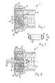
- Fig.1 einen axialen Schnitt durch den vorderen Teil eines Zylinderschlosses mit der abdichtenden Rolle in der verschliessenden Stellung;
- Fig. 2 einen axialen Schnitt durch den vorderen Teil des Zylinderschlosses mit eingeführtem Schlüssel und zur Seite hin verdrängter Rolle; und
- Fig. 3 eine Seitenansicht der Rolle in grösserem Massstab als in den Figuren 1 und 2.
- Ein Schliesszylinder 1 weist ein Zylindergehäuse 2 auf, in dem koaxial ein Zylinderkern 3 drehbar und axial unverschieblich gelagert ist. Der Zylinderkern 3 weist an seiner Vorderseite eine koaxiale topfförmige Ausnehmung4 auf, in die ein zylindrisches Dichtteil 5 grösseren Durchmessers als Höhe einliegt, wobei das Dichtteil 5 die Ausnehmung 4 ausfüllt und damit die Aussenabmessungen des Dichtteils 5 etwa den Abmessungen der Ausnehmung 4 entsprechen. Die Ausnehmung 4 ist vorne durch eine vordere metallene Kappe 6 abgeschlossen, die seitlich zumindest teilweise das Dichtteil 5 mit einem koaxialen zylindrischen Kragen 7 umgreift. Aussen liegt auf dem Zylindergehäuse ein dieses seitlich umgreifender Montagering 8 an, der die Kappe 6 aussen zu einem Teil übergreift und somit dafür sorgt, dass Kappe 6 und Dichtteil 5 am bzw. im Zylinderkern 3 gehalten sind.
- Der Zylinderkern 3 ist in Längsrichtung von einem Schlüsselkanal 9 durchdrungen, der sich durch das Dichtteil 5 nach vorne fortsetzt und in einer entsprechend geformten Öffnung 10 der Kappe 6 mündet. Nahe der Öffnung 10 bildet das Dichtteil 5 auf der der Öffnung 10 abgewandten Seite einen teilzylindrischen Dichtsitz bzw. ein Dichtbett 11, das zu beiden Seiten an den Schlüsselkanal im Bereich des Dichtteils anschliesst. In diesem Dichtbett 11, dessen Achse rechtwinklig zur Zylinderachse ist und diese schneidet, liegt eine zylindrische bzw.walzenförmige Rolle 12 ein, die in dieser den Schlüsselkanal verschliessenden Stellung nicht nur rechtwinklig zur Zylinderachse ist, sondern auch in dieser Stellung die Zylinderachse mit ihrer Achse schneidet. Da das Dichtteil 5 aus einem elastischen Kunststoff besteht und die Rolle 12 durch eine Schraubendruckfeder 13 in den Sitz 11 gedrückt wird, erreicht die Rolle 12 eine sichere Abdichtung des Schlüsselkanals 9.
- Der Durchmesser D der Rolle 12 ist grösser als die Breite B des Schlüsselkanals 9, so dass das äusserste Ende des Schlüsselkanals 9 im Bereich des Dichtteils 5 dafür sorgt, dass die Rolle nicht nach aussen gedrückt wird. Die Rolle weist auf beiden Seiten zwei koaxiale Zapfen 14 auf, die in seitlichen, schräg zur Zylinderachse, insbesondere in 45° schrägen, zu beiden Seiten angeordneten Führungen 15 des Zylinderkerns gleiten. Etwa in Richtung dieser schräg verlaufenden Führungen 15 ist auch die Schraubendruckfeder 13 seitlich angeordnet. Wird der Schlüssel 16 mit seiner Spitze in die Öffnung 10 eingeführt, so verdrängt die Schlüsselspitze die Rolle 12 gegen den Druck der Feder 13 zur Seite, so dass die Rolle 12 den Schlüsselkanal 9 freigibt und in der in Fig. 2 dargestellten Stellung sich befindet. Nach Abzug des Schlüssels drückt die Feder 13 die Rolle wieder in den Sitz 11.
- Bei Montage des Schlosses wird der Zylinderkern 3 in den Schliesszylinder 1 eingeschoben, dann das Dichtteil 5 von vorne in die Ausnehmung 4 eingebracht, die Feder 13 und danach die Rolle 12 gegen den Druck der Feder eingesetzt, die Kappe 6 von vorne aufgebracht und danach der Montagering 8 aufgesetzt und hinter den äusseren Rand des Zylindergehäuses 2 umgebördelt. Damit lassen sich die einzelnen Teile automatisch nacheinander auf einfachste Weise einbringen, ohne die Feder vorher spannen zu müssen.
Claims (7)
Applications Claiming Priority (2)
| Application Number | Priority Date | Filing Date | Title |
|---|---|---|---|
| DE19863608304 DE3608304A1 (de) | 1986-03-13 | 1986-03-13 | Schliesszylinder mit verschluss des schluesselkanals |
| DE3608304 | 1986-03-13 |
Publications (2)
| Publication Number | Publication Date |
|---|---|
| EP0241587A1 EP0241587A1 (de) | 1987-10-21 |
| EP0241587B1 true EP0241587B1 (de) | 1988-12-28 |
Family
ID=6296201
Family Applications (1)
| Application Number | Title | Priority Date | Filing Date |
|---|---|---|---|
| EP86115685A Expired EP0241587B1 (de) | 1986-03-13 | 1986-11-12 | Schliesszylinder mit Verschluss des Schlüsselkanals |
Country Status (3)
| Country | Link |
|---|---|
| EP (1) | EP0241587B1 (de) |
| DE (2) | DE3608304A1 (de) |
| ES (1) | ES2005056B3 (de) |
Cited By (1)
| Publication number | Priority date | Publication date | Assignee | Title |
|---|---|---|---|---|
| RU202297U1 (ru) * | 2018-12-25 | 2021-02-10 | Общество с ограниченной ответственностью "Флорус" | Конструкция вращающегося сегмента |
Families Citing this family (1)
| Publication number | Priority date | Publication date | Assignee | Title |
|---|---|---|---|---|
| DE102020129633A1 (de) * | 2020-11-10 | 2022-05-12 | ABUS August Bremicker Söhne Kommanditgesellschaft | Schlüssellochverdeck |
Family Cites Families (6)
| Publication number | Priority date | Publication date | Assignee | Title |
|---|---|---|---|---|
| DE1931009A1 (de) * | 1969-06-19 | 1970-12-23 | Fritz Juengst | Vorrichtung zum staubdichten Verschliessen der Schluessel-Einfuehrungsoeffnung an Drehzylinderschloessern |
| DE2058802C3 (de) * | 1970-11-30 | 1980-02-28 | Neiman & Co Kg, 5600 Wuppertal | Lenkschloß für Kraftfahrzeuge |
| FR2264150A1 (en) * | 1974-03-15 | 1975-10-10 | Antivols Simplex Sa | Sliding keyhole cover for cylinder lock - is spring loaded and slides on slotted cylinder cap |
| DE2441463C3 (de) * | 1974-08-29 | 1980-04-17 | Neiman Gmbh + Co Kg, 5600 Wuppertal | Zylinderschlofi mit einem axial verschiebbaren Zylinderkern, insbesondere für ein Lenkschloß in Kraftfahrzeugen |
| CH596415A5 (de) * | 1975-05-28 | 1978-03-15 | Berchtold Ag | |
| FR2481733A1 (fr) * | 1980-04-30 | 1981-11-06 | Sodex Magister | Serrure a barillet comportant un volet basculant d'obturation du canal de cle |
-
1986
- 1986-03-13 DE DE19863608304 patent/DE3608304A1/de not_active Withdrawn
- 1986-11-12 DE DE8686115685T patent/DE3661560D1/de not_active Expired
- 1986-11-12 EP EP86115685A patent/EP0241587B1/de not_active Expired
- 1986-11-12 ES ES86115685T patent/ES2005056B3/es not_active Expired - Lifetime
Cited By (1)
| Publication number | Priority date | Publication date | Assignee | Title |
|---|---|---|---|---|
| RU202297U1 (ru) * | 2018-12-25 | 2021-02-10 | Общество с ограниченной ответственностью "Флорус" | Конструкция вращающегося сегмента |
Also Published As
| Publication number | Publication date |
|---|---|
| DE3661560D1 (en) | 1989-02-02 |
| ES2005056B3 (es) | 1990-09-16 |
| DE3608304A1 (de) | 1987-09-24 |
| EP0241587A1 (de) | 1987-10-21 |
Similar Documents
| Publication | Publication Date | Title |
|---|---|---|
| DE69208627T2 (de) | Wasserdichte Verbinder | |
| DE8424654U1 (de) | Steckverbinder, insbesondere Rundsteckverbinder | |
| DE3218751A1 (de) | Dichtungseinrichtung | |
| DE69308786T2 (de) | Verbinder mit Bedienungshebel | |
| DE2636827A1 (de) | Klinkvorrichtung | |
| CH661091A5 (de) | Verschlussmechanismus an einer mit einem deckel versehene kassette. | |
| EP0433659B1 (de) | Thermostatventil | |
| DE2265773C3 (de) | Absperrschieber | |
| EP1342030A1 (de) | Gassteckdose | |
| DE2442010A1 (de) | Hydraulikkopf fuer eine einspritzpumpe und mit diesem hydraulikkopf ausgeruestete einspritzpumpe | |
| DD202065A5 (de) | Vorrichtung zur befestigung eines deckels auf einem gehaeuse, insbesondere auf einem schiebergehaeuse | |
| DE3603998A1 (de) | Drosselklappenventil | |
| DE2016620B2 (de) | Drosselklappenventil | |
| CH660410A5 (de) | Mehrwege-hahn. | |
| EP0241587A1 (de) | Schliesszylinder mit Verschluss des Schlüsselkanals | |
| DE69026782T2 (de) | Verriegelungsvorrichtung für Verbinder | |
| EP1063110B1 (de) | Einstellbares Ventil für die Zufuhr von Kühlungsluft zu einem Handschuhfach | |
| DE2537572A1 (de) | Fahrzeugtuerscharnier | |
| DE2904290A1 (de) | Verschlussanordnung | |
| DE4425980C2 (de) | Absperreinrichtung für eine gasführende Leitung | |
| WO2022100983A1 (de) | Schlüssellochverdeck | |
| DE69001652T2 (de) | Türschliesser. | |
| DE2654688A1 (de) | Zylindrischer hahn | |
| DE10155940A1 (de) | Klappe zur Verwendung in Rauchgas- oder Luftkanälen | |
| DE3009983A1 (de) | U-foermiges dichtelement |
Legal Events
| Date | Code | Title | Description |
|---|---|---|---|
| PUAI | Public reference made under article 153(3) epc to a published international application that has entered the european phase |
Free format text: ORIGINAL CODE: 0009012 |
|
| 17P | Request for examination filed |
Effective date: 19870418 |
|
| AK | Designated contracting states |
Kind code of ref document: A1 Designated state(s): DE ES FR GB IT |
|
| 17Q | First examination report despatched |
Effective date: 19880527 |
|
| GRAA | (expected) grant |
Free format text: ORIGINAL CODE: 0009210 |
|
| AK | Designated contracting states |
Kind code of ref document: B1 Designated state(s): DE ES FR GB IT |
|
| REF | Corresponds to: |
Ref document number: 3661560 Country of ref document: DE Date of ref document: 19890202 |
|
| ITF | It: translation for a ep patent filed | ||
| GBT | Gb: translation of ep patent filed (gb section 77(6)(a)/1977) | ||
| ET | Fr: translation filed | ||
| PLBE | No opposition filed within time limit |
Free format text: ORIGINAL CODE: 0009261 |
|
| STAA | Information on the status of an ep patent application or granted ep patent |
Free format text: STATUS: NO OPPOSITION FILED WITHIN TIME LIMIT |
|
| 26N | No opposition filed | ||
| ITTA | It: last paid annual fee | ||
| PGFP | Annual fee paid to national office [announced via postgrant information from national office to epo] |
Ref country code: GB Payment date: 19971028 Year of fee payment: 12 |
|
| PGFP | Annual fee paid to national office [announced via postgrant information from national office to epo] |
Ref country code: ES Payment date: 19971105 Year of fee payment: 12 |
|
| PGFP | Annual fee paid to national office [announced via postgrant information from national office to epo] |
Ref country code: FR Payment date: 19971120 Year of fee payment: 12 |
|
| PGFP | Annual fee paid to national office [announced via postgrant information from national office to epo] |
Ref country code: DE Payment date: 19980122 Year of fee payment: 12 |
|
| PG25 | Lapsed in a contracting state [announced via postgrant information from national office to epo] |
Ref country code: GB Free format text: LAPSE BECAUSE OF NON-PAYMENT OF DUE FEES Effective date: 19981112 |
|
| PG25 | Lapsed in a contracting state [announced via postgrant information from national office to epo] |
Ref country code: ES Free format text: LAPSE BECAUSE OF THE APPLICANT RENOUNCES Effective date: 19981113 |
|
| GBPC | Gb: european patent ceased through non-payment of renewal fee |
Effective date: 19981112 |
|
| PG25 | Lapsed in a contracting state [announced via postgrant information from national office to epo] |
Ref country code: FR Free format text: LAPSE BECAUSE OF NON-PAYMENT OF DUE FEES Effective date: 19990730 |
|
| REG | Reference to a national code |
Ref country code: FR Ref legal event code: ST |
|
| PG25 | Lapsed in a contracting state [announced via postgrant information from national office to epo] |
Ref country code: DE Free format text: LAPSE BECAUSE OF NON-PAYMENT OF DUE FEES Effective date: 19990901 |
|
| REG | Reference to a national code |
Ref country code: ES Ref legal event code: FD2A Effective date: 20010402 |
|
| PG25 | Lapsed in a contracting state [announced via postgrant information from national office to epo] |
Ref country code: IT Free format text: LAPSE BECAUSE OF NON-PAYMENT OF DUE FEES;WARNING: LAPSES OF ITALIAN PATENTS WITH EFFECTIVE DATE BEFORE 2007 MAY HAVE OCCURRED AT ANY TIME BEFORE 2007. THE CORRECT EFFECTIVE DATE MAY BE DIFFERENT FROM THE ONE RECORDED. Effective date: 20051112 |