EP0241552B1 - Regelung des ladens von unter druck stehenden, elektrischen gas-metall-ladungszellen - Google Patents
Regelung des ladens von unter druck stehenden, elektrischen gas-metall-ladungszellen Download PDFInfo
- Publication number
- EP0241552B1 EP0241552B1 EP87900356A EP87900356A EP0241552B1 EP 0241552 B1 EP0241552 B1 EP 0241552B1 EP 87900356 A EP87900356 A EP 87900356A EP 87900356 A EP87900356 A EP 87900356A EP 0241552 B1 EP0241552 B1 EP 0241552B1
- Authority
- EP
- European Patent Office
- Prior art keywords
- cell
- charging
- change
- characteristic
- rate
- Prior art date
- Legal status (The legal status is an assumption and is not a legal conclusion. Google has not performed a legal analysis and makes no representation as to the accuracy of the status listed.)
- Expired - Lifetime
Links
Images



Classifications
-
- H—ELECTRICITY
- H01—ELECTRIC ELEMENTS
- H01M—PROCESSES OR MEANS, e.g. BATTERIES, FOR THE DIRECT CONVERSION OF CHEMICAL ENERGY INTO ELECTRICAL ENERGY
- H01M10/00—Secondary cells; Manufacture thereof
- H01M10/34—Gastight accumulators
- H01M10/345—Gastight metal hydride accumulators
-
- H—ELECTRICITY
- H01—ELECTRIC ELEMENTS
- H01M—PROCESSES OR MEANS, e.g. BATTERIES, FOR THE DIRECT CONVERSION OF CHEMICAL ENERGY INTO ELECTRICAL ENERGY
- H01M10/00—Secondary cells; Manufacture thereof
- H01M10/42—Methods or arrangements for servicing or maintenance of secondary cells or secondary half-cells
-
- H—ELECTRICITY
- H01—ELECTRIC ELEMENTS
- H01M—PROCESSES OR MEANS, e.g. BATTERIES, FOR THE DIRECT CONVERSION OF CHEMICAL ENERGY INTO ELECTRICAL ENERGY
- H01M10/00—Secondary cells; Manufacture thereof
- H01M10/42—Methods or arrangements for servicing or maintenance of secondary cells or secondary half-cells
- H01M10/44—Methods for charging or discharging
- H01M10/445—Methods for charging or discharging in response to gas pressure
-
- H—ELECTRICITY
- H02—GENERATION; CONVERSION OR DISTRIBUTION OF ELECTRIC POWER
- H02J—ELECTRIC POWER NETWORKS; CIRCUIT ARRANGEMENTS OR SYSTEMS FOR SUPPLYING OR DISTRIBUTING ELECTRIC POWER; SYSTEMS FOR STORING ELECTRIC ENERGY
- H02J7/00—Circuit arrangements for charging or discharging batteries or for supplying loads from batteries
- H02J7/90—Regulation of charging or discharging current or voltage
- H02J7/971—Regulation of charging or discharging current or voltage the charge cycle being controlled or terminated in response to non-electric parameters
- H02J7/973—Regulation of charging or discharging current or voltage the charge cycle being controlled or terminated in response to non-electric parameters in response to degree of gas development in the battery
-
- Y—GENERAL TAGGING OF NEW TECHNOLOGICAL DEVELOPMENTS; GENERAL TAGGING OF CROSS-SECTIONAL TECHNOLOGIES SPANNING OVER SEVERAL SECTIONS OF THE IPC; TECHNICAL SUBJECTS COVERED BY FORMER USPC CROSS-REFERENCE ART COLLECTIONS [XRACs] AND DIGESTS
- Y02—TECHNOLOGIES OR APPLICATIONS FOR MITIGATION OR ADAPTATION AGAINST CLIMATE CHANGE
- Y02E—REDUCTION OF GREENHOUSE GAS [GHG] EMISSIONS, RELATED TO ENERGY GENERATION, TRANSMISSION OR DISTRIBUTION
- Y02E60/00—Enabling technologies; Technologies with a potential or indirect contribution to GHG emissions mitigation
- Y02E60/10—Energy storage using batteries
Definitions
- This invention relates generally to pressurized gas-metal storage cells such as sealed nickel-hydrogen cells and, more particularly, to controlling the charging of such cells.
- Rechargeable storage cells are electrochemical devices for storing an electrical charge and later delivering that charge as a useful current.
- a familiar example of the rechargeable storage cell is the lead-acid battery used in automobiles.
- Another type of cell having a greater electrical storage capacity per unit weight is the pressurized gas-metal storage cell, an important example of which is the nickel-hydrogen cell used in spacecraft applications.
- a nickel-hydrogen cell used in a satellite is typically periodically charged by electrical current produced by solar panels on the spacecraft, and then later discharged to supply electrical power, when the spacecraft is in shadow or the solar panels are otherwise unable to furnish electrical power.
- the primary requirements of storage cells to be used in spacecraft are high energy capacity per unit weight of cell, reliability, and the ability to be recycled through many cycles of charging and discharging. Reliability and multiple cycle capability are influenced in part by the degree of charging of the cell. That is, it has been found that nickel-hydrogen cells tend to have a shorter life and greater incidence of failures if the cells are severely overcharged during the charging cycle.
- US-A-4392101 discloses a method of fast charging nickel cadmium batteries by means of analysis of the profile of the variation with time of the battery voltage which is indicative of the variation in stored chemical energy as the battery is charged.
- the method specifically comprises analyzing the profile for the occurrence of a particular series of events including one or more inflection points which precisely identify the point in time at which the application of a fast charge rate should be discontinued. Additional methods of analysis provide for termination or control of the charging current upon the occurrence of other events such as limiting values on time or voltage or a negative change in the level of stored energy.
- the method disclosed is apparently applicable also to nickel-iron, lead-acid, lithium (iron-sulphide electrode), and silver-cadmium batteries.
- the present invention resides in a method and apparatus for controlling the charging of pressurized gas-metal cells, to prevent the detrimental overcharging of such cells.
- the approach allows the reproducible limitation of cell charging, without regard to the age, temperature, charging rate, or other parameters, within the normal operating limits of typical spacecraft operations. No significant modifications to the cell itself are required, and the decisional and control functions can be accomplished using either a small hardware controller or a digital computer to monitor the instrumentation of the cell. Control may be accomplished entirely without outside intervention, so that charging requires no contact with a ground computer or controller.
- a storage cell charging controller comprising first means for determining the time rate of change of a characteristic of a cell; and second means for discontinuing the charging of the cell in response to the determined rate of change, characterised in that the controller is adapted for use with a gas-metal storage cell; the said characteristic is a quantity which responsively and functionally varies with the gas pressure within the cell; and the said second means for discontinuing charging of the cell is adapted to do so when the absolute value of the determined rate of change falls and remains below the absolute value of a predetermined value.
- the said characteristic can be the gas pressure itself or a responsive quantity such as the deformation of one of the cell components.
- the rate of change of the said characteristic can vary widely within a short period of time, even during slow charging of the cell. It is therefore important to filter out or otherwise avoid the adverse effects of the variation, to obtain a true measure of the rate of change of the characteristic with time.
- the controller therefore desirably includes means for calculating an averaged value of the rate of change of the said characteristic.
- the averaging may be accomplished in any appropriate manner, such as by averaging several successive values of the rate of change, or by obtaining two averaged values of the said characteristic and then dividing by the average time between obtaining the values. Whatever approach is used, when the rate of change falls below the preselected value, then it is concluded that the cell is approaching a full charge, and charging is discontinued, except for a possible trickle charge to maintain the charged state.
- the said characteristic is the deformation of the wall of the cell pressure vessel, as measured by a strain gauge or transducer mounted on the external wall of the pressure vessel. As the pressure within the vessel rises, the wall deforms, and the strain gauge measures this deformation as produced by the internal pressure. Because of random variation of the characteristic, the measured value of the rate of change varies widely about a true value. It is therefore preferred to measure a plurality of values of the rate of change, as on the order of about 33 values in a two minute period, and then to average these values to derive a true, reliable value of the rate of change. If this average value falls below the preselected value, then it is concluded that the cell is fully charged within the operational error limits of this procedure, and the charging is discontinued. To insure consistency, the preferred controller requires that two or more consecutive values of the averaged value of the rate of change must be below the preselected level, to be certain that random variation has not caused an incorrect determination of full charging.
- the calculations can be made either by fully dedicated hardware, by a digital computer, or by a combined device such as a microprocessor working from a read-only memory. All of the necessary hardware and support functions can be placed adjacent the cell so that control of charging does not require the intervention of a ground-based controller.
- the invention provides a method of charging a storage cell comprising determining the time rate of change of a characteristic of the cell; and discontinuing the charging of the cell in response to the determined rate of change; characterised in that the cell is a gas-metal storage cell; the said characteristic is a quantity which responsively and functionally varies with the gas pressure within the cell; and discontinuing the charging of the cell includes comparing the determined rate of change with a predetermined value and discontinuing the charging when the absolute value of the rate of change falls and remains below the absolute value of the predetermined value.
- the present invention represents an advance in the art of pressurized gas-metal storage cells, and particularly in the long-lifetime operation of such cells.
- cell charging can be limited to optimal levels, without reliance upon assumptions about internal gas pressure, charging rate, or other features.
- the rate of change of the said characteristic is reduced, and this reduced rate of change triggers the termination of the charging operation.
- Charging may therefore be commenced from any level of discharge, without knowing the value of that discharge level. This capability is important, in as much as the charge ⁇ discharge cycles can vary significantly depending upon the orbital position, the sun angle, and other flight parameters.
- the present invention is desirably used in conjunction with a nickel-hydrogen storage cell 10, as illustrated in FIGURES 1 and 2, of the pressurized gas-metal cell type.
- a cell 10 typically comprises a plurality of individual plate sets 12.
- Each plate set 12 in turn comprises an anode or positive electrode 14, a cathode or negative electrode 16, and an electrolyte-containing separator 18, which physically separates the electrodes 14 and 16, and also supplies the electrolyte medium through which ionic and electron transfer occur.
- Charging and discharging of the plate set 12 are accomplished through electrical leads 20.
- the positive electrode 14 is formed by impregnating nickel hydroxide into porous sintered nickel that is supported on an etched nickel electrode substrate.
- the negative electrode 16 is coated on one side by a sintered mixture of platinum black and polytetrafluoroethylene and on the other side with a porous layer of polytetrafluoroethylene 19. These layers are applied to a nickel substrate in the form of etched sheet or a woven mesh, to form the negative electrode 16.
- separators 18 Many different types have been used, including, for example, asbestos, nylon, and a cloth of zirconium oxide-yttrium oxide containing polysulfone.
- the electrolyte preferrably potassium hydroxide, is impregnated into the separator 18.
- the individual plate sets 12 are assembled onto a central core 22 to form a stacked array 24.
- a monofilament polypropylene screen 26 is placed between each plate set 12, so that oxygen liberated during overcharging at each positive electrode 14 can diffuse away from the electrode 14 and to the negative electrode 16 to combine with hydrogen.
- the stacked array 24 is placed under a longitudinal pressure of, for example, about 69.0 kPa (10 pounds per square inch), by tightening compression plates 28 against each end of the stacked array 24.
- the tightening of the compression plates 28 is preferably accomplished by compressing the array 24 and then tightening a nut 30 on threads on the core 22, thereby compressing a Belleville washer set 32 against the compression plate 28 to hold the stacked array 24 in place.
- the stacked array 24 is sealed within a pressure vessel 34, manufactured of a material such as Inconel 718 nickel-based alloy which can withstand internal pressures on the order of 6.9 MPa (1,000 psi), without damage by hydrogen embrittlement or corrosion by the electrolyte.
- a gas fill tube 35 allows gas content and pressure within the pressure vessel 34 to be controlled.
- the pressure vessel 34 is typically constructed in the form of a cylindrical tube having domed ends.
- the cell 10 having the pressure vessel 34 of external dimensions 8.89 cm (3-1/2 inches) diameter and 33 cm (13 inches) long can contain about 40 individual plate sets 12, with a resulting electrical storage capacity of the cell of about 50 ampere-hours.
- the cell 10 may be charged and discharged through thousands of cycles without apparent damage, if the charging and discharging are accomplished properly.
- a number of cells 10 can be combined in series or parallel to produce a battery.
- Charging is accomplished by impressing a voltage through the leads 20 across each plate set 12 so that electrons flow from the electrode 16 to the electrode 14. Electrical energy is thereby stored in each plate set in the form of chemical reactants, for subsequent discharging to produce a usable current.
- a nickel-hydrogen cell of the type described previously may be fully charged by a solar cell array to a capacity of, for example, about 50 ampere hours, using a current of about 5 amperes at 1.5 volts, through a charging period of about 14 hours from a discharged state.
- the voltage and charging time vary, depending upon the power available from the solar cell and the cycle dictated by the orbit of the spacecraft.
- the rise in pressure may be measured directly by a pressure transducer 36, which measures the pressure within the pressure vessel 34.
- the rise in pressure may also be deduced by measuring a quantity which responds to pressure, specifically the deformation in the wall 38 of the pressure vessel 34. That is, as the pressure within the pressure vessel 34 increases, the pressure vessel tends to expand and bulge slightly.
- a strain gauge 40 fastened to the wall 38 of the pressure vessel 34 measures the bulging of the wall, which is a function of, and preferably proportional to, the internal gas pressure within the vessel 34.
- the pressure itself or a responsive quantity such as deformation of a cell component can be used as the gas pressure index.
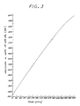
- FIGURE 3 is a graph of the gauge pressure actually measured within the pressure vessel 34 as a function of time during charging, for one set of charging conditions. Charging was accomplished with a current of approximately 4.8 amperes, at voltages up to 1.5 volts. As may be seen in FIGURE 3, the pressure varies approximately linearly with time until the pressure reaches approximately 3.59 MPa (520 psi). Thereafter, the pressure continues to rise but at a lesser rate, toward a value which reaches approximately 4.14 MPa (600 psi) after 450 minutes.
- FIGURE 4 illustrates the time rate of change of the voltage output of the strain gauge 40 during the same test illustrated in FIGURE 3, which voltage output is a measure of deformation of the wall 38 of the pressure vessel 34, which deformation is in turn a measure of the pressure within the pressure vessel 34.
- the voltage output of the strain gauge 40 is therefore a quantity responsive to the gas pressure for the cell 10. If the charging conditions were varied, the curves in FIGURES 3 and 4 would change.
- the test of FIGURES 3 and 4 was conducted at a laboratory ambient temperature of about 20°C, but typical variations in temperature on board a spacecraft could result in changes in the curves of FIGURES 3 and 4. Some temperature effects can be compensated, but others are more difficult to correct. These effects make control of cell charging, through pressure alone, difficult without intervention of the ground controller.
- the present invention provides that, when the time rate of change of the cell gas pressure index falls below a preselected value during the charging of the cell, charging is discontinued.
- the preselected value is determined by observing the optimum performance of the pressurized gas-metal cell for various charging levels or by other factors.
- a preferred preselected value is slightly less than about one-half the steady state rate of change during charging. That is, typically when the time rate of change of voltage falls below about 1.5 mv per minute, charging is discontinued. For the conditions of FIGURES 3 and 4, charging would be discontinued after approximately 460 minutes.
- FIGURE 4 may be readily used after the fact to determine the time for discontinuing the charging, such a determination is more difficult when conducted in real time.
- the time rate of change as a function of time varies widely, due to random variation. It is therefore necessary either to filter out the noise or, preferably, to average a number of values to determine an apparent true value of the curve at a particular time.
- the true value of the rate of change of the cell pressure index is calculated as the average of several values.
- FIGURE 5 depicts the approach used. A value of voltage is read from the strain gauge 40, and the time of the reading is also recorded. Then the time rate of change from the last reading of voltage and time is determined. This calculation is performed by calculating the difference between the current voltage reading and the last prior voltage reading, and dividing this difference by the time interval between taking the two readings. This time rate of change can vary widely, and in the preferred approach 33 such values, each determined about 3.6 seconds apart, are averaged to obtain the average apparent true value.
- the average apparent true value is compared with the preselected value, or, preferably, a set of two or more average values are each compared with the preselected value.
- the reason for comparing several average apparent true values with the preselected value is apparent from FIGURE 4, which is the graph of the average apparent true values as a function of time.
- FIGURE 4A shows the actual data points for each 2-minute average over 33 data points. Even after averaging, the data still varies somewhat. The averaged values vary from a smooth curve through the points, and it is possible that a single averaged value might lie below the preselected value before the optimal charging is reached.
- the calculations previously described have been performed using a digital computer in the presently preferred approach.
- the calculations would preferably be performed by a microprocessor operating from an instruction set in a permanent read-only memory.
- the calculations may also be performed by dedicated hardware elements where the analog pressure signals are converted to digital information and processed according to a procedure such as illustrated in FIGURE 5.
- the controller and procedure disclosed herein have been operated in an autonomous fashion to demonstrate that no external intervention is required.
- a nickel-hydrogen cell has been repeatedly charged to an optimal level using the preferred approach, and then discharged.
- Such an approach allows the cell charging and discharging to be correctly performed even in the absence of telemetry, radio contact, and a human controller for extended periods, a requirement for certain types of satellite.
- the present approach may be distinguished from the prior approach, wherein the magnitude of the gas pressure was compared with a predetermined value.
- the time rate of change of the gas pressure or a quantity responsive thereto is compared with a preselected value.
Landscapes
- Engineering & Computer Science (AREA)
- Manufacturing & Machinery (AREA)
- Chemical & Material Sciences (AREA)
- Chemical Kinetics & Catalysis (AREA)
- Electrochemistry (AREA)
- General Chemical & Material Sciences (AREA)
- Power Engineering (AREA)
- Hybrid Cells (AREA)
- Secondary Cells (AREA)
- Charge And Discharge Circuits For Batteries Or The Like (AREA)
- Battery Electrode And Active Subsutance (AREA)
Claims (13)
- Ein Speicherzellenladesteuergerät, welches eine erste Vorrichtung (40) umfaßt, zum Bestimmen der zeitlichen Änderung einer Charakteristik einer Zelle (10), sowie eine zweite Vorrichtung, um das Aufladen der Zelle (10) in Antwort auf die bestimmte Änderungsrate zu unterbrechen, dadurch gekennzeichnet, daß das Steuergerät für die Verwendung mit einer Gas-Metall-Speicherzelle (10) angepaßt ist; die Charakteristik eine Größe ist, welche im Hinblick auf das Ansprechverhalten und funktionell mit dem Gasdruck innerhalb der Zelle (10) variiert; und die zweite Vorrichtung zum Unterbrechen der Aufladung der Zelle (10) angepaßt ist, dies zu tun, wenn der Absolutwert der bestimmten Änderungsrate unterhalb des Absolutwertes eines vorherbestimmten Wertes fällt und dort verbleibt.
- Das Steuergerät nach Anspruch 1, das für die Verwendung mit einer Nickel-Wasserstoffzelle angepaßt ist.
- Das Steuergerät nach Anspruch 1 oder 2, in dem die erste Vorrichtung Vorrichtungen zum Messen der mechanischen Deformation einer Komponente der Zelle enthält, und worin die Deformation die Charakteristik ist.
- Das Steuergerät nach einem der Ansprüche 1 bis 3, worin die erste Vorrichtung einen Dehnungsmeßstreifen (40) enthält, der angepaßt ist, um an einer externen Wand (38) der Zelle (10) befestigt zu werden, und worin der Spannungsausgang des Dehnungsmeßstreifens (40) die Charakteristik ist.
- Das Steuergerät nach einem der Ansprüche 1 oder 2, worin die erste Vorrichtung Vorrichtungen (36) enthält, zum Messen des Gasdruckes innerhalb der Zelle, und worin der Gasdruck selbst die Charakteristik ist.
- Das Steuergerät nach einem der vorigen Ansprüche, in dem die erste Vorrichtung Vorrichtungen zum Bestimmen eines gemittelten Wertes der Änderungsrate der Charakteristik enthält.
- Das Steuergerät nach Anspruch 6, worin die erste Vorrichtung wenigstens zwei ungemittelte Werte der Änderungsrate der Charakteristik mittelt.
- Das Steuergerät nach Anspruch 6 oder 7, worin die erste Vorrichtung einen Digitalcomputer umfaßt.
- Ein Verfahren zum Aufladen einer Speicherzelle (10), das die Bestimmung der zeitlichen Änderung einer Charakteristik der Zelle (10) umfaßt, sowie das Unterbrechen des Aufladens der Zelle in Antwort auf die bestimmte Änderungsrate, dadurch gekennzeichnet, daß die Zelle eine Gas-Metallspeicherzelle ist, die Charakteristik eine Größe ist, welche im Hinblick auf das Ansprechverhalten und funktionell mit dem Gasdruck innerhalb der Zelle variiert; und das Unterbrechen des Aufladens der Zelle den Vergleich der bestimmten Änderungsrate mit einem vorherbestimmten Wert enthält, sowie das Unterbrechen des Aufladens, wenn der Absolutwert des Ladens unterhalb dem Absolutwert des vorherbestimmten Wertes fällt und dort verbleibt.
- Verfahren nach Anspruch 9, worin die Zelle eine Nickel-Wasserstoffzelle ist.
- Verfahren nach Anspruch 9 oder 10, worin die Charakteristik der Gasdruck innerhalb der Zelle ist.
- Das Verfahren nach Anspruch 9 oder 10, worin die Charakteristik die mechanische Deformation unter Druck einer Komponente der Zelle ist.
- Verfahren nach Anspruch 9 oder 12, worin die Charakteristik der Spannungsausgang eines Dehnungsmeßstreifens ist, der auf externen Wand der Zelle befestigt ist.
Applications Claiming Priority (3)
| Application Number | Priority Date | Filing Date | Title |
|---|---|---|---|
| US06/788,593 US4689544A (en) | 1985-10-17 | 1985-10-17 | Control of the charging of pressurized gas-metal electrical storage cells |
| US788593 | 1985-10-17 | ||
| US06/827,023 US4683178A (en) | 1985-10-17 | 1986-02-07 | Process for preventing electrical storage cell capacity loss |
Publications (2)
| Publication Number | Publication Date |
|---|---|
| EP0241552A1 EP0241552A1 (de) | 1987-10-21 |
| EP0241552B1 true EP0241552B1 (de) | 1993-01-27 |
Family
ID=39620129
Family Applications (2)
| Application Number | Title | Priority Date | Filing Date |
|---|---|---|---|
| EP87900356A Expired - Lifetime EP0241552B1 (de) | 1985-10-17 | 1986-09-15 | Regelung des ladens von unter druck stehenden, elektrischen gas-metall-ladungszellen |
| EP87900591A Expired - Lifetime EP0254730B1 (de) | 1985-10-17 | 1986-12-29 | Verfahren zur verhinderung des kapazitätsverlustes einer elektrochemischen speicherzelle |
Family Applications After (1)
| Application Number | Title | Priority Date | Filing Date |
|---|---|---|---|
| EP87900591A Expired - Lifetime EP0254730B1 (de) | 1985-10-17 | 1986-12-29 | Verfahren zur verhinderung des kapazitätsverlustes einer elektrochemischen speicherzelle |
Country Status (6)
| Country | Link |
|---|---|
| US (2) | US4689544A (de) |
| EP (2) | EP0241552B1 (de) |
| JP (2) | JPH0793152B2 (de) |
| CA (2) | CA1257900A (de) |
| DE (2) | DE3687655T2 (de) |
| WO (2) | WO1987002515A2 (de) |
Families Citing this family (64)
| Publication number | Priority date | Publication date | Assignee | Title |
|---|---|---|---|---|
| US4888702A (en) * | 1987-08-20 | 1989-12-19 | Integrated Power Corporation | Photovoltaic system controller |
| US4800140A (en) * | 1987-10-02 | 1989-01-24 | The Aerospace Corporation | Apparatus and method for preventing degradation of nickel hydrogen cells and batteries |
| US4820597A (en) * | 1987-12-11 | 1989-04-11 | Hughes Aircraft Company | Extended life nickel-hydrogen storage cell |
| US4950564A (en) * | 1988-05-02 | 1990-08-21 | Gates Energy Products, Inc. | Metal gas cell |
| US4904551A (en) * | 1988-07-18 | 1990-02-27 | Gates Energy Products, Inc. | Ceramic seal assembly |
| AU619640B2 (en) * | 1989-01-18 | 1992-01-30 | Comsat Corporation | Method for rejuvenating ni-h2 batteries |
| US5100745A (en) * | 1989-01-18 | 1992-03-31 | Communications Satellite Corporation | Method for rejuvenating Ni-H2 batteries |
| US5030524A (en) * | 1989-01-19 | 1991-07-09 | Hughes Aircraft Company | Battery cell stack having extended life |
| US4965145A (en) * | 1989-08-01 | 1990-10-23 | Hughes Aircraft Company | Electrical storage cell resistant to freezing |
| US5082754A (en) * | 1990-05-24 | 1992-01-21 | Globe-Union Inc. | Pressure vessel construction for a metal oxide-hydrogen battery |
| US5071652A (en) * | 1990-12-11 | 1991-12-10 | Globe-Union Inc. | Metal oxide hydrogen battery having improved heat transfer properties |
| US5215835A (en) * | 1991-09-11 | 1993-06-01 | Globe-Union Inc. | Metal oxide-hydrogen battery having an outer safety shell |
| JPH05121103A (ja) * | 1991-10-25 | 1993-05-18 | Fujitsu Ltd | 二次電池充電方法 |
| US5168017A (en) * | 1991-10-28 | 1992-12-01 | Globe-Union Inc. | Metal oxide-hydrogen battery having rectangular modules in a cylindrical pressure vessel |
| US5173377A (en) * | 1991-10-28 | 1992-12-22 | Globe-Union Inc. | Apparatus for electrically connecting cell modules of a metal oxide-hydrogen battery |
| US5162171A (en) * | 1991-10-28 | 1992-11-10 | Globe-Union Inc. | Metal oxide-hydrogen battery having modules extending longitudinally of the pressure vessel |
| US5173376A (en) * | 1991-10-28 | 1992-12-22 | Globe-Union Inc. | Metal oxide hydrogen battery having sealed cell modules with electrolyte containment and hydrogen venting |
| US5327784A (en) * | 1992-07-09 | 1994-07-12 | Ovonic Battery Company, Inc. | Apparatus for measuring the pressure inside a rechargeable electrochemical cell |
| US5290640A (en) * | 1993-03-10 | 1994-03-01 | Acme Electric Corporation | Sealed rechargeable battery |
| US5310609A (en) * | 1993-05-25 | 1994-05-10 | Comsat | Battery cell terminal seal/intercell connector |
| US5438249A (en) * | 1993-06-08 | 1995-08-01 | Valence Technology, Inc. | Method of state-of-charge indication by measuring the thickness of a battery |
| US5569554A (en) * | 1994-09-15 | 1996-10-29 | Acme Electric Corporation | Sealed rechargeable battery with stabilizer |
| KR960024447A (ko) * | 1994-12-28 | 1996-07-20 | 윤종용 | 전지의 내압 측정장치 |
| EP0767984B1 (de) * | 1995-04-28 | 2000-09-20 | Koninklijke Philips Electronics N.V. | Batterieladevorrichtung |
| US5763118A (en) * | 1996-05-09 | 1998-06-09 | Hughes Aircraft Company | Battery system with a high-thermal-conductivity split shell structural support |
| US5786107A (en) * | 1996-05-09 | 1998-07-28 | Hughes Electronics | Battery system with a high-thermal-conductivity integral structural support |
| US5695888A (en) * | 1996-06-11 | 1997-12-09 | He Holdings, Inc. | Pressurized-gas energy storage cell with insulated catalytic surfaces |
| US5916703A (en) * | 1996-07-16 | 1999-06-29 | Hughes Electronics | Energy storage cell with hydrogen vent |
| US5763115A (en) * | 1996-07-16 | 1998-06-09 | Stadnick; Steven J. | Resetting the precharge of a group of pressurized gas energy storage cells during service |
| US5837399A (en) * | 1997-07-22 | 1998-11-17 | Hughes Electronics Corporation | Through-wall electrical terminal and energy storage cell utilizing the terminal |
| US6146786A (en) * | 1998-07-20 | 2000-11-14 | Hughes Electronics Corporation | Electrochemical storage cell having a central core providing mechanical, thermal, and electrical functions |
| US6163134A (en) * | 2000-01-27 | 2000-12-19 | Hughes Electronics Corporation | Temperature compensation of the pressure cutoff of charging of a pressurized-gas storage battery |
| US6229282B1 (en) | 2000-03-22 | 2001-05-08 | Hughes Electronics Corporation | Low-voltage-drop, spring-activated bypass of failed battery cell |
| EP1164680B1 (de) * | 2000-04-28 | 2016-08-10 | Panasonic Corporation | Ladeverfahren für Batteriesatz mit einer Vielzahl Batterieeinheiten |
| NO20004463L (no) * | 2000-09-07 | 2002-03-08 | Norsk Hydro As | Trykksatte metallhydridbatterier |
| RU2210842C2 (ru) * | 2001-09-20 | 2003-08-20 | Открытое акционерное общество "Ракетно-космическая корпорация "Энергия" им. С.П. Королева" | Способ эксплуатации герметичной металл-водородной аккумуляторной батареи космического аппарата в процессе полета и система для его осуществления |
| US10629947B2 (en) | 2008-08-05 | 2020-04-21 | Sion Power Corporation | Electrochemical cell |
| RU2262162C1 (ru) * | 2004-03-16 | 2005-10-10 | Открытое акционерное общество "Ракетно-космическая корпорация "Энергия" имени С.П. Королева" | Способ контроля герметичности металл-водородного аккумулятора |
| RU2262780C1 (ru) * | 2004-03-16 | 2005-10-20 | Открытое акционерное общество "Ракетно-космическая корпорация "Энергия" им. С.П. Королева" | Способ контроля герметичности металл-водородного аккумулятора |
| JP2007053058A (ja) * | 2005-08-19 | 2007-03-01 | Toyota Motor Corp | 二次電池の内圧推定装置及びそれを備えた二次電池の充電制御装置 |
| RU2324262C2 (ru) * | 2006-03-10 | 2008-05-10 | Открытое акционерное общество "Ракетно-космическая корпорация "Энергия" имени С.П. Королева" | Способ управления энергоемкостью металл-водородной аккумуляторной батареи с общим газовым коллектором |
| DE102006038713A1 (de) * | 2006-05-10 | 2007-11-29 | Schunk Kohlenstofftechnik Gmbh | Druckfester fluidbeaufschlagter Körper |
| US9105938B2 (en) | 2008-08-05 | 2015-08-11 | Sion Power Corporation | Application of force in electrochemical cells |
| WO2009089018A2 (en) * | 2008-01-08 | 2009-07-16 | Sion Power Corporation | Porous electrodes and associated methods |
| US20100192362A1 (en) * | 2008-09-11 | 2010-08-05 | A123 System, Inc. | Split Charge Forming Process for Battery |
| EP2409349A4 (de) * | 2009-03-19 | 2013-05-01 | Sion Power Corp | Kathode für lithiumbatterie |
| US20110206992A1 (en) * | 2009-08-28 | 2011-08-25 | Sion Power Corporation | Porous structures for energy storage devices |
| WO2011031297A2 (en) * | 2009-08-28 | 2011-03-17 | Sion Power Corporation | Electrochemical cells comprising porous structures comprising sulfur |
| JP5575441B2 (ja) * | 2009-09-29 | 2014-08-20 | Necパーソナルコンピュータ株式会社 | 充電制御装置、充電制御方法、プログラム及び記録媒体 |
| EP2721665B1 (de) | 2011-06-17 | 2021-10-27 | Sion Power Corporation | Verfahren zur plattierung einer elektrode |
| CN103947027B (zh) | 2011-10-13 | 2016-12-21 | 赛昂能源有限公司 | 电极结构及其制造方法 |
| US9077041B2 (en) | 2012-02-14 | 2015-07-07 | Sion Power Corporation | Electrode structure for electrochemical cell |
| KR101991149B1 (ko) | 2012-12-19 | 2019-06-19 | 시온 파워 코퍼레이션 | 전극 구조물 및 그의 제조 방법 |
| US12261284B2 (en) | 2013-03-15 | 2025-03-25 | Sion Power Corporation | Protective structures for electrodes |
| KR102622781B1 (ko) | 2014-05-01 | 2024-01-08 | 시온 파워 코퍼레이션 | 전극 제조 방법 및 관련 제품 |
| JP6864536B2 (ja) * | 2017-04-25 | 2021-04-28 | 株式会社東芝 | 二次電池システム、充電方法、プログラム、及び車両 |
| US10868306B2 (en) | 2017-05-19 | 2020-12-15 | Sion Power Corporation | Passivating agents for electrochemical cells |
| JP7210475B2 (ja) | 2017-05-19 | 2023-01-23 | シオン・パワー・コーポレーション | 電気化学セルの不動態化剤 |
| WO2020257414A1 (en) | 2019-06-21 | 2020-12-24 | Sion Power Corporation | Methods, systems, and devices for applying forces to electrochemical devices |
| US11978917B2 (en) | 2019-11-19 | 2024-05-07 | Sion Power Corporation | Batteries with components including carbon fiber, and associated systems and methods |
| US11791511B2 (en) | 2019-11-19 | 2023-10-17 | Sion Power Corporation | Thermally insulating compressible components for battery packs |
| US11824228B2 (en) | 2019-11-19 | 2023-11-21 | Sion Power Corporation | Compression systems for batteries |
| US11984575B2 (en) | 2019-11-19 | 2024-05-14 | Sion Power Corporation | Battery alignment, and associated systems and methods |
| EP4118701A1 (de) | 2020-03-13 | 2023-01-18 | Sion Power Corporation | Anwendung von druck auf elektrochemische vorrichtungen mit verformbaren feststoffen und zugehörige systeme |
Family Cites Families (15)
| Publication number | Priority date | Publication date | Assignee | Title |
|---|---|---|---|---|
| DE1175302B (de) * | 1957-12-21 | 1964-08-06 | Varta Ag | Staendig gas- und fluessigkeitsdicht verschlossener alkalischer Akkumulator |
| FR1309917A (fr) * | 1961-10-09 | 1962-11-23 | Fulmen | Résistance électrique variable et application à un régulateur électrique |
| BE662702A (de) * | 1965-04-20 | 1965-08-17 | ||
| US3278334A (en) * | 1963-06-25 | 1966-10-11 | Union Carbide Corp | Anode limited sealed secondary battery having an auxiliary electrode |
| US3403317A (en) * | 1966-01-27 | 1968-09-24 | Milton A. Knight | Battery charging controller |
| US3427523A (en) * | 1966-08-01 | 1969-02-11 | Sylvania Electric Prod | Pressure responsive battery charging apparatus |
| US3990910A (en) * | 1972-05-31 | 1976-11-09 | Tyco Laboratories, Inc. | Nickel-hydrogen battery |
| US3867199A (en) * | 1972-06-05 | 1975-02-18 | Communications Satellite Corp | Nickel hydrogen cell |
| US3959018A (en) * | 1972-11-27 | 1976-05-25 | Communications Satellite Corporation | Low pressure nickel hydrogen cell |
| US4143212A (en) * | 1976-10-18 | 1979-03-06 | Tokyo Shibaura Electric Co., Ltd. | Sealed storage battery |
| US4174565A (en) * | 1977-06-28 | 1979-11-20 | Union Carbide Corporation | Method of precharging rechargeable metal oxide-hydrogen cells |
| US4207514A (en) * | 1977-11-21 | 1980-06-10 | Energy Research Corporation | System and apparatus for monitoring or controlling secondary battery operation |
| US4198594A (en) * | 1978-04-25 | 1980-04-15 | Yardney Electric Corporation | Method of charging a vented alkaline electrolyte-containing electrochemical cell |
| US4392101A (en) * | 1978-05-31 | 1983-07-05 | Black & Decker Inc. | Method of charging batteries and apparatus therefor |
| US4275127A (en) * | 1979-06-19 | 1981-06-23 | Trw Inc. | Sealed nickel-cadmium battery with self-regulating precharge adjustment capability |
-
1985
- 1985-10-17 US US06/788,593 patent/US4689544A/en not_active Expired - Lifetime
-
1986
- 1986-02-07 US US06/827,023 patent/US4683178A/en not_active Expired - Lifetime
- 1986-09-15 DE DE8787900356T patent/DE3687655T2/de not_active Expired - Fee Related
- 1986-09-15 WO PCT/US1986/001900 patent/WO1987002515A2/en not_active Ceased
- 1986-09-15 JP JP62500052A patent/JPH0793152B2/ja not_active Expired - Lifetime
- 1986-09-15 EP EP87900356A patent/EP0241552B1/de not_active Expired - Lifetime
- 1986-10-16 CA CA000520666A patent/CA1257900A/en not_active Expired
- 1986-12-29 EP EP87900591A patent/EP0254730B1/de not_active Expired - Lifetime
- 1986-12-29 JP JP62500592A patent/JPH0787103B2/ja not_active Expired - Lifetime
- 1986-12-29 WO PCT/US1986/002787 patent/WO1987004863A1/en not_active Ceased
- 1986-12-29 DE DE8787900591T patent/DE3673821D1/de not_active Expired - Fee Related
-
1987
- 1987-02-02 CA CA000528776A patent/CA1284355C/en not_active Expired - Fee Related
Also Published As
| Publication number | Publication date |
|---|---|
| EP0254730B1 (de) | 1990-08-29 |
| JPS63501111A (ja) | 1988-04-21 |
| CA1257900A (en) | 1989-07-25 |
| DE3673821D1 (de) | 1990-10-04 |
| DE3687655D1 (de) | 1993-03-11 |
| EP0254730A1 (de) | 1988-02-03 |
| WO1987002515A2 (en) | 1987-04-23 |
| JPS63502310A (ja) | 1988-09-01 |
| CA1284355C (en) | 1991-05-21 |
| WO1987004863A1 (en) | 1987-08-13 |
| WO1987002515A3 (en) | 1987-07-16 |
| US4683178A (en) | 1987-07-28 |
| DE3687655T2 (de) | 1993-06-03 |
| JPH0793152B2 (ja) | 1995-10-09 |
| US4689544A (en) | 1987-08-25 |
| EP0241552A1 (de) | 1987-10-21 |
| JPH0787103B2 (ja) | 1995-09-20 |
Similar Documents
| Publication | Publication Date | Title |
|---|---|---|
| EP0241552B1 (de) | Regelung des ladens von unter druck stehenden, elektrischen gas-metall-ladungszellen | |
| US7244527B2 (en) | Multi-cell battery charge control | |
| US4820597A (en) | Extended life nickel-hydrogen storage cell | |
| CA2157930C (en) | Sealed rechargeable battery | |
| CA2884449C (en) | Management of gas pressure and electrode state of charge in alkaline batteries | |
| US5248510A (en) | Cobalt oxide passivation of nickel battery electrode substrates | |
| EP0892449A1 (de) | Elektrochemische Zelle mit einem durch ein Spritzverfahren hergestellten, porösen Separator | |
| US6163134A (en) | Temperature compensation of the pressure cutoff of charging of a pressurized-gas storage battery | |
| US5030524A (en) | Battery cell stack having extended life | |
| US5584892A (en) | Process for producing nickel electrode having lightweight substrate | |
| US4965145A (en) | Electrical storage cell resistant to freezing | |
| US5763115A (en) | Resetting the precharge of a group of pressurized gas energy storage cells during service | |
| US5916703A (en) | Energy storage cell with hydrogen vent | |
| Wheeler | High specific energy, high capacity nickel-hydrogen cell design | |
| Verzwyvelt et al. | The measurement of nickel hydrogen cell performance characteristics with pressure as a state of charge indication | |
| Kulin et al. | Life cycle testing of a sealed 42-Ah, 24-V nickel-cadmium aircraft battery | |
| JPS6046516B2 (ja) | 密閉型蓄電池の過充電検出方法 | |
| JPH08308114A (ja) | シール鉛蓄電池の寿命判定方法 | |
| Luksha et al. | Non-gassing nickel-cadmium battery electrodes and cells: Testing of 25 Ah cells | |
| Howard et al. | Development of a sealed lead-acid battery for use in space Final report | |
| Catotti et al. | Development of a nickel cadmium storage cell immune to damage from overdischarge and overcharge | |
| Chedister et al. | Study of Bipolar Nickel-Cadmium Batteries as Pulsed Load Filters. |
Legal Events
| Date | Code | Title | Description |
|---|---|---|---|
| PUAI | Public reference made under article 153(3) epc to a published international application that has entered the european phase |
Free format text: ORIGINAL CODE: 0009012 |
|
| 17P | Request for examination filed |
Effective date: 19870602 |
|
| AK | Designated contracting states |
Kind code of ref document: A1 Designated state(s): DE FR GB |
|
| 17Q | First examination report despatched |
Effective date: 19910523 |
|
| GRAA | (expected) grant |
Free format text: ORIGINAL CODE: 0009210 |
|
| AK | Designated contracting states |
Kind code of ref document: B1 Designated state(s): DE FR GB |
|
| REF | Corresponds to: |
Ref document number: 3687655 Country of ref document: DE Date of ref document: 19930311 |
|
| ET | Fr: translation filed | ||
| PLBE | No opposition filed within time limit |
Free format text: ORIGINAL CODE: 0009261 |
|
| STAA | Information on the status of an ep patent application or granted ep patent |
Free format text: STATUS: NO OPPOSITION FILED WITHIN TIME LIMIT |
|
| 26N | No opposition filed | ||
| PGFP | Annual fee paid to national office [announced via postgrant information from national office to epo] |
Ref country code: FR Payment date: 19940808 Year of fee payment: 9 |
|
| PGFP | Annual fee paid to national office [announced via postgrant information from national office to epo] |
Ref country code: GB Payment date: 19940815 Year of fee payment: 9 |
|
| PGFP | Annual fee paid to national office [announced via postgrant information from national office to epo] |
Ref country code: DE Payment date: 19940824 Year of fee payment: 9 |
|
| PG25 | Lapsed in a contracting state [announced via postgrant information from national office to epo] |
Ref country code: GB Effective date: 19950915 |
|
| GBPC | Gb: european patent ceased through non-payment of renewal fee |
Effective date: 19950915 |
|
| PG25 | Lapsed in a contracting state [announced via postgrant information from national office to epo] |
Ref country code: FR Effective date: 19960531 |
|
| PG25 | Lapsed in a contracting state [announced via postgrant information from national office to epo] |
Ref country code: DE Effective date: 19960601 |
|
| REG | Reference to a national code |
Ref country code: FR Ref legal event code: ST |