EP0241332A2 - Opto-elektronische Vorrichtung zum Detektieren einer physikalischen Grösse aus der Entfernung - Google Patents
Opto-elektronische Vorrichtung zum Detektieren einer physikalischen Grösse aus der Entfernung Download PDFInfo
- Publication number
- EP0241332A2 EP0241332A2 EP87400573A EP87400573A EP0241332A2 EP 0241332 A2 EP0241332 A2 EP 0241332A2 EP 87400573 A EP87400573 A EP 87400573A EP 87400573 A EP87400573 A EP 87400573A EP 0241332 A2 EP0241332 A2 EP 0241332A2
- Authority
- EP
- European Patent Office
- Prior art keywords
- sensor
- sensors
- physical quantity
- spectral
- signals
- Prior art date
- Legal status (The legal status is an assumption and is not a legal conclusion. Google has not performed a legal analysis and makes no representation as to the accuracy of the status listed.)
- Granted
Links
Images
Classifications
-
- G—PHYSICS
- G01—MEASURING; TESTING
- G01D—MEASURING NOT SPECIALLY ADAPTED FOR A SPECIFIC VARIABLE; ARRANGEMENTS FOR MEASURING TWO OR MORE VARIABLES NOT COVERED IN A SINGLE OTHER SUBCLASS; TARIFF METERING APPARATUS; MEASURING OR TESTING NOT OTHERWISE PROVIDED FOR
- G01D5/00—Mechanical means for transferring the output of a sensing member; Means for converting the output of a sensing member to another variable where the form or nature of the sensing member does not constrain the means for converting; Transducers not specially adapted for a specific variable
- G01D5/26—Mechanical means for transferring the output of a sensing member; Means for converting the output of a sensing member to another variable where the form or nature of the sensing member does not constrain the means for converting; Transducers not specially adapted for a specific variable characterised by optical transfer means, i.e. using infrared, visible, or ultraviolet light
- G01D5/32—Mechanical means for transferring the output of a sensing member; Means for converting the output of a sensing member to another variable where the form or nature of the sensing member does not constrain the means for converting; Transducers not specially adapted for a specific variable characterised by optical transfer means, i.e. using infrared, visible, or ultraviolet light with attenuation or whole or partial obturation of beams of light
- G01D5/34—Mechanical means for transferring the output of a sensing member; Means for converting the output of a sensing member to another variable where the form or nature of the sensing member does not constrain the means for converting; Transducers not specially adapted for a specific variable characterised by optical transfer means, i.e. using infrared, visible, or ultraviolet light with attenuation or whole or partial obturation of beams of light the beams of light being detected by photocells
- G01D5/344—Mechanical means for transferring the output of a sensing member; Means for converting the output of a sensing member to another variable where the form or nature of the sensing member does not constrain the means for converting; Transducers not specially adapted for a specific variable characterised by optical transfer means, i.e. using infrared, visible, or ultraviolet light with attenuation or whole or partial obturation of beams of light the beams of light being detected by photocells using polarisation
-
- G—PHYSICS
- G01—MEASURING; TESTING
- G01K—MEASURING TEMPERATURE; MEASURING QUANTITY OF HEAT; THERMALLY-SENSITIVE ELEMENTS NOT OTHERWISE PROVIDED FOR
- G01K11/00—Measuring temperature based upon physical or chemical changes not covered by groups G01K3/00, G01K5/00, G01K7/00 or G01K9/00
Definitions
- the invention relates to a method and a device for opto-electronic remote detection of physical quantities, by means of sensors which each comprise a sensitive element whose spectral transmission varies according to a physical quantity to be measured, which are illuminated by a incoherent beam of light which transmit light signals to spectral analysis means.
- thermochromic solution sensors are known for which temperature variations result in large variations in the absorption spectrum of the sensitive medium.
- An exemplary embodiment of such a sensor is described in the article M. Breci et al. "Thermocromic Transducer Optical Fiber Temperature Sensor", 2nd International Conference on Optical Fiber Sensors, September 5 - 7, 1984.
- Colorimetric type sensors are also known, in which variations in the composition of a binary mixture result in variations in its trichromatic components.
- a sensor of this type is described in French Patent No. 85 08 550 of 6 June 1985.
- the present invention aims in particular to provide a simple solution to this problem by allowing the multiplexing on the same optical fiber of spectral information using the same light source and therefore the same carrier.
- the invention proposes a method of opto-electronic remote detection of physical quantities by means of sensors which each comprise a sensitive element whose spectral transmission varies according to a quantity, physical to be measured, which are illuminated by a incoherent beam of light which transmit light signals to spectral analysis means, characterized in that it consists in coding the signals of the sensors by superimposing on the light transmitted by the sensitive element of each sensor a periodic modulation or quasi-periodic of its spectrum at a frequency characteristic of the sensor considered, to transmit these signals thus modulated by the same optical fiber to the aforementioned means of spectral analysis, to effect a decoding or demultiplexing of the signals by Fourier transformation optically for isolate the signal relating to each sensor, then drag this signal to obtain the value of the physical quantity corresponding.
- the coding by spectrum modulation is carried out by means of a two-wave interferometer, comprising for example a birefringent plate of determined constitution which is associated with the sensitive element of the sensor, the demultiplexing being carried out by means of an interferometer with two waves of the same constitution, comprising for example a birefringent plate identical to that of the sensor.
- the method also consists in that for each sensor, the signal resulting from the Fourier transformation is recorded and a mathematical operation of the inverse Fourier transform type performed by digital means is applied to it.
- the frequency of the spectral modulation of a sensor varies as a function of a second physical quantity different from that acting on the sensitive element of the sensor, and the signal resulting from the demultiplexing by Fourier transformation allows to go back simultaneously to the values of these two quantities.
- the sensitive elements of the sensors can be of the all-or-nothing type with respect to a predetermined value of the corresponding physical quantity, and the apparent intensity of the demultiplexed signal from each sensor is then recorded to deduce the state of the physical quantity in relation to its predetermined value.
- the invention also proposes a device for opto-electronic remote sensing of physical quantities comprising an incoherent light source connected by optical fiber to sensors which each comprise a sensitive element whose spectral transmission varies according to a physical quantity to be measured. and which are connected by optical fiber to spectral analysis means, characterized in that each sensor comprises a coding means by spectral modulation carrying out a periodic or quasi-periodic modulation of the light transmitted by the sensitive element at a characteristic frequency of the sensor in question, each sensor being connected to the spectral analysis means by an optical fiber common to all the sensors, and in that the spectral analysis means comprise a two-wave interferometer performing optically a Fourier transformation of the signals received from sensors to identify, thanks to its characteristic frequency, the signal relating to ch aque sensor, the device also comprising means for detecting demultiplexed signals and means for processing these signals to deduce therefrom the values of the physical quantities detected.
- the coding means by spectral modulation is a two-wave interferometer, making it possible to introduce between these two waves a path difference characteristic of the corresponding sensor.
- this interferometer comprises a birefringent plate of determined constitution placed between crossed or parallel polarizers in the immediate vicinity of the sensitive element of the sensor.
- the demultiplexing interferometer then comprises a set of birefringent plates, each of which is identical to the birefringent plate of a corresponding sensor, and means for bringing the plates one by one onto the optical axis of the interferometer.
- the detection means comprise means for recording the demultiplexed signal relating to each sensor, and the processing means comprise means for digitally producing an inverse Fourier transform applied to the recorded signal.
- the sensitive elements of the sensors are of the all-or-nothing operating type with respect to a predetermined value of the corresponding physical quantity. In this case, it suffices to record the apparent intensity of the demultiplexed signal relating to each sensor, to deduce therefrom whether the physical quantity considered is greater or less than its predetermined value.
- the invention therefore allows the multiplexing, on the same optical fiber, of the signals transmitted by several sensors for detecting a physical quantity, the demultiplexing of these signals, and their processing to obtain the values of minus two physical quantities at several measurement points.
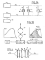
- the device according to the invention is shown diagrammatically in FIG. 1A and comprises a source 10 of incoherent light, such as a filament lamp or a light-emitting diode, connected by an optical fiber 12 of emission and connection fibers 14 to sensors C 1, C 2, ..., C i, ... each associated with a device DC 1, DC 2, ..., DC i, ... for coding by spectral modulation of the light transmitted by a corresponding sensor element, which is sensitive to a physical quantity to be measured.
- the sets C 1 - DC 1, C 2-DC 2, ... are connected by optical fibers 16 for connection to a common optical fiber 18 for reception, which leads to a demodulation device 20 associated with circuits 22 for detection and treatment.
- FIG. 1 B The operation of a sensor-coding device assembly is illustrated diagrammatically in FIG. 1 B.
- B ( ⁇ ) denotes the spectrum of the light signal incident on the sensor, ⁇ being the wave number.
- the sensitive element of the sensor C i is subjected to the physical quantity X to be measured, which is for example the temperature, and its spectral transmission is designated by Ti ( ⁇ , X).
- the coding device D C i is an interferometric system with two waves, which makes it possible to introduce between these two waves a path difference ⁇ i characteristic of the sensor considered.
- This sensor transmits an envelope spectrum B ( ⁇ ) Ti ( ⁇ , X) representative of the state of the physical quantity X at the level of the sensor, to which is added a sinusoidal periodic modulation of frequency ⁇ i characteristic of the sensor considered.
- This light flux is transmitted by the optical fiber 18 to the demodulation device 20 which, by means of a two-wave interferometer, performs a Fourier transformation optically of this light flux.
- the signal obtained is written: where D is the difference in gait in the demodulation interferometer and i (D) is the Fourier cosine transform of the term B ( ⁇ ) Ti ( ⁇ , X).
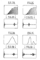
- FIGS. 2 A, 2 B, 2 C and 2 D illustrate the influence of the value of the modulation frequency ⁇ i on the light flux.
- FIGS. 2 A and 2 C schematically represent any light spectrum coded by two different modulation frequencies.
- FIGS. 2 B and 2 D represent the signals obtained after demodulation by transformation of Fourier, the signal of Figure 2 B corresponding to the flow of Figure 2 A and the signal of Figure 2 D corresponding to the flow of Figure 2 C.
- the lateral responses + ⁇ i do are not obtained for the same values of the path difference D and can therefore be easily identified and isolated insofar as the difference between the coding frequencies associated with any two sensors is greater than the spatial extension of the Fourier transform of the flux transmitted by each sensor.
- FIGS. 3 A, 3 B, 3 C and 3 D illustrate the influence of the variations in spectral transmission of the sensors on the shape of the lateral responses + ⁇ i obtained after demodulation by Fourier transformation.
- the spectra transmitted by the sensitive elements of the sensors are represented in FIGS. 3 A and 3 c, while the corresponding lateral responses + ⁇ i are represented in FIGS. 3 B and 3 D. It can be seen that the information contained in the spectrum transmitted by the sensitive element of a sensor is in direct relation with the information which is contained in the demodulated signal, this relation being of the Fourier transformation type.
- the method and the device according to the invention do indeed make it possible to multiplex spectral information from several sensors and using the same incoherent carrier on the same optical line.
- the detection means of the circuits 22 record the zones of the interferogram corresponding to the lateral responses + ⁇ i relating to the various sensors. For each sensor, the useful signal is therefore of the form:
- the first term corresponds to the superposition of the continuous components relating to the various sensors
- the second term is directly related to the behavior of the sensor C i considered.
- the continuous background corresponding to the sum of the first terms of the relation is removed, in order to digitize only the useful signal corresponding to the second term of this relationship.
- a reference channel similar in its constitution to a set C i ⁇ D C i, but not comprising sensitive elements.
- the processing of the demultiplexed signal corresponding to this reference channel makes it possible to determine the spectral distribution of energy of the light source, that is to say B ( ⁇ ) and to better specify the effective variations in transmission Ti ( ⁇ , X ) relating to the various sensors.
- the sensitive elements of the various sensors C i can be of the all-or-nothing type, their spectral transmission varying suddenly around a given value of the physical quantity X to be measured.
- Ti ( ⁇ , X) T i ( ⁇ ) if X> X0
- the spectral information proper is of little interest, and the evaluation of the integrated transmission of the sensitive element suffices to define the situation of the physical quantity X with respect to its predetermined value X0 for which the spectral transmission of the sensitive element varies suddenly.
- the useful signal is written as follows:
- a simple phase modulation of 2 ⁇ around the tuning position ⁇ i makes it possible to evaluate the amplitude B T0 of the useful signal and therefore to deduce therefrom if the sensitive element of the sensor is in a state of spectral transmission corresponding to a value of X ⁇ X0, or in a state of spectral transmission corresponding to a value of X> X0.
- the use of a reference channel not comprising sensitive elements can prove to be advantageous insofar as it makes it possible to constantly readjust the transmission of the various sensors and therefore to free up light source operating drifts.
- FIG. 4 shows a preferred embodiment of the sensor-coding device assembly according to the invention.
- the end of the optical fiber 14 connecting the light source 10 to the sensor is placed at the focus of a collimating optic 24 which provides a parallel light beam forming a polarizer P.
- This polarizer is followed by a plate 26 of uniaxial birefringent material, cut parallel to its axis, then by an analyzer A and by the sensitive element 28 of the sensor, whose spectral transmission varies according to the physical quantity X to be measured.
- the light transmitted by this assembly is taken up by an exit optic 30 at the focal point of which is placed the end of the optical fiber 16 connected by the optical fiber 18 to the demodulation device 20.
- the blade 26 is characterized by a slow axis d 'index n L and a fast axis with index n R.
- This path difference has a certain spectral dependence, so that it is advantageous to use in the demodulation device a birefringent interferometer of the same constitution and having a similar spectral dependence, so as to compensate for its effects differentially.
- This compensation is all the more useful as the light source used is of wide spectral width (case of a filament lamp).
- the birefringent interferometer used for the demodulation of information may be a scanning interferometer (for example of the Bravais type) or a static interferometer (of the Babinet or Wollaston type).
- a scanning interferometer the recording of the useful signal is obtained by means of a single photoelectric detector, during the movement of a mobile element making it possible to continuously vary the path difference in the interferometer.
- a static interferometer the useful signal relating to each sensor is recorded using a multi-point detector, such as a charge transfer CCD diode array, the variation in the path difference being obtained in the field of the interferometer without moving a moving part.
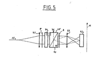
- FIG. 5 A preferred embodiment of the demodulation interferometer is shown in FIG. 5.
- the end of the optical fiber 18 is placed at the focus of a collimating optic 32 providing a parallel light beam arriving on a polarizer P.
- This polarizer is followed by a blade 34 of birefringent material, of constitution identical to that of the blade 26 of FIG. 4.
- This blade 34 of birefringent material is followed by a Wollaston prism 36, consisting of two elementary birefringent prisms 38 and 40 which are joined along an oblique face with respect to the optical axis of the system and which are arranged in a crossed manner, the slow axis of the elementary prism 38 being coincident with the fast axis of the elementary prism 40.
- the Wollaston prism 36 is followed by an analyzer A associated with an output optic 41 forming an image of the interference fringe field on a multipoint linear detector 42, for example of the CC diode type D.
- the polarizer assembly P - analyzer A is in cross or parallel configuration, and the direction of polarization makes an angle of 45 ° with the neutral axes of the birefringent plate 34.
- the path difference D introduced by this demodulation system 20 varies linearly along a preferred optical direction x which is perpendicular to the optical axis and along which the photosensitive elements of the multipoint detector 42 are aligned.
- each birefringent plate 34 of the demodulation system which corresponds to the birefringent plate 26 of a sensor - coding device assembly, is carried by a disc mounted to rotate about an axis parallel to the optical axis of the system. of demodulation and associated with motor means making it possible to rotate this disk, in order to successively bring the birefringent blades onto the optical axis of the system, which makes it possible to demultiplex the light signals transmitted by the receiving optical fiber 18.
- the sensors used in the device according to the invention may include elements sensitive to a first physical quantity X to be measured, for example the concentration of a binary medium, while the modulation frequency characteristic of each sensor can vary as a function of another physical quantity Y such as temperature.
- the demodulation, detection and processing means used in the invention make it possible to go back simultaneously to the values of these two physical quantities, insofar as: the location of the lateral response + ⁇ in the demodulated signal makes it possible to quantify the value of the modulation frequency used for coding (and therefore to obtain the value of the physical quantity Y), - recording the demodulated signal around the path difference + ⁇ , allows, after appropriate processing (removal of the continuous background and inverse Fourier transformation) to determine the spectral transmission of the sensitive element of the sensor (and therefore the value of the magnitude X.
- the separate measurement of the second physical quantity Y makes it possible to overcome the dependence of the spectral transmission on Y, and therefore to go back exactly to the value of the physical quantity X.
Landscapes
- General Physics & Mathematics (AREA)
- Physics & Mathematics (AREA)
- Optical Transform (AREA)
- Investigating Or Analysing Materials By Optical Means (AREA)
- Measurement Of Optical Distance (AREA)
- Arrangements For Transmission Of Measured Signals (AREA)
- Measuring Fluid Pressure (AREA)
- Instruments For Measurement Of Length By Optical Means (AREA)
- Length Measuring Devices By Optical Means (AREA)
- Measuring Instrument Details And Bridges, And Automatic Balancing Devices (AREA)
- Measuring Temperature Or Quantity Of Heat (AREA)
- Light Guides In General And Applications Therefor (AREA)
- Testing Or Calibration Of Command Recording Devices (AREA)
Priority Applications (1)
| Application Number | Priority Date | Filing Date | Title |
|---|---|---|---|
| AT87400573T ATE60131T1 (de) | 1986-03-13 | 1987-03-13 | Opto-elektronische vorrichtung zum detektieren einer physikalischen groesse aus der entfernung. |
Applications Claiming Priority (2)
| Application Number | Priority Date | Filing Date | Title |
|---|---|---|---|
| FR8603598A FR2595820B1 (fr) | 1986-03-13 | 1986-03-13 | Dispositif a fibres optiques pour la detection a distance d'une grandeur physique, en particulier de la temperature |
| FR8603598 | 1986-03-13 |
Publications (3)
| Publication Number | Publication Date |
|---|---|
| EP0241332A2 true EP0241332A2 (de) | 1987-10-14 |
| EP0241332A3 EP0241332A3 (en) | 1988-06-08 |
| EP0241332B1 EP0241332B1 (de) | 1991-01-16 |
Family
ID=9333090
Family Applications (2)
| Application Number | Title | Priority Date | Filing Date |
|---|---|---|---|
| EP87400572A Expired - Lifetime EP0242250B1 (de) | 1986-03-13 | 1987-03-13 | Opto-elektronische Vorrichtung zum Detektieren einer physikalischen Grösse aus der Entfernung |
| EP87400573A Expired - Lifetime EP0241332B1 (de) | 1986-03-13 | 1987-03-13 | Opto-elektronische Vorrichtung zum Detektieren einer physikalischen Grösse aus der Entfernung |
Family Applications Before (1)
| Application Number | Title | Priority Date | Filing Date |
|---|---|---|---|
| EP87400572A Expired - Lifetime EP0242250B1 (de) | 1986-03-13 | 1987-03-13 | Opto-elektronische Vorrichtung zum Detektieren einer physikalischen Grösse aus der Entfernung |
Country Status (9)
| Country | Link |
|---|---|
| US (2) | US4867565A (de) |
| EP (2) | EP0242250B1 (de) |
| JP (2) | JPH0781814B2 (de) |
| AT (2) | ATE60132T1 (de) |
| DE (2) | DE3767349D1 (de) |
| ES (2) | ES2021067B3 (de) |
| FR (1) | FR2595820B1 (de) |
| GR (2) | GR3001777T3 (de) |
| WO (2) | WO1987005691A2 (de) |
Families Citing this family (44)
| Publication number | Priority date | Publication date | Assignee | Title |
|---|---|---|---|---|
| FR2626367B1 (fr) * | 1988-01-25 | 1990-05-11 | Thomson Csf | Capteur de temperature multipoints a fibre optique |
| US4859844A (en) * | 1988-02-24 | 1989-08-22 | Hughes Aircraft Company | Comb filter pressure/temperature sensing system |
| FR2632404B1 (fr) * | 1988-06-03 | 1990-09-21 | Elf Aquitaine | Capteur interferometrique et son utilisation dans un dispositif interferometrique |
| GB2224114A (en) * | 1988-09-12 | 1990-04-25 | Secr Defence | Fourier transform ultra-violet visible instrument |
| FR2641861B1 (fr) * | 1989-01-18 | 1993-04-30 | Photonetics | Dispositif de mesure opto-electronique |
| FR2643145A1 (fr) * | 1989-02-14 | 1990-08-17 | Bertin & Cie | Procede et dispositif de detection et de mesure d'une grandeur physique |
| FR2643730B1 (fr) * | 1989-02-24 | 1991-09-20 | Bertin & Cie | Dispositif opto-electronique a codage spectral de la lumiere, et ses applications |
| FR2648600B1 (fr) * | 1989-06-14 | 1991-09-27 | Bertin & Cie | Appareil opto-electronique de mesure a distance d'une grandeur physique |
| FR2661003B2 (fr) * | 1989-12-26 | 1992-06-12 | Commissariat Energie Atomique | Capteur de champ electrique a effet pockels. |
| GB2239944B (en) * | 1990-01-08 | 1993-12-08 | York Ltd | An optical fibre coupled sensor system |
| FR2657161B1 (fr) * | 1990-01-12 | 1994-05-27 | Bertin & Cie | Dispositif de detection a distance d'une grandeur physique, fonctionnant en reflexion. |
| FR2673023B1 (fr) * | 1991-02-14 | 1993-06-11 | Bertin & Cie | Recepteur de demultiplexage sequentiel pour un reseau de capteurs optiques a codage de modulation spectrale. |
| DE69206654T2 (de) * | 1991-03-26 | 1996-07-11 | Hamamatsu Photonics Kk | Optischer Spannungsdetektor |
| US5191458A (en) * | 1991-06-12 | 1993-03-02 | Grumman Aerospace Corporation | Optical electronic multiplexing reflection sensor system |
| EP0604582A1 (de) * | 1991-09-18 | 1994-07-06 | Iowa State University Research Foundation, Inc. | Zwei-wellenlängen-photometer und faseroptischer sensor |
| US5317524A (en) * | 1991-09-19 | 1994-05-31 | Allied-Signal Inc. | Spectral signal analyzer system |
| US5255068A (en) * | 1991-11-25 | 1993-10-19 | Allied-Signal Inc. | Fringe pattern analysis of a birefringent modified spectrum to determine environmental temperature |
| US5299869A (en) * | 1992-08-19 | 1994-04-05 | Hughes Aircraft Company | Laser diode temperature sensing system |
| US5323229A (en) * | 1992-08-31 | 1994-06-21 | Science Applications International Corporation | Measurement system using optical coherence shifting interferometry |
| US5513913A (en) * | 1993-01-29 | 1996-05-07 | United Technologies Corporation | Active multipoint fiber laser sensor |
| US5381010A (en) * | 1993-12-03 | 1995-01-10 | Sleepair Corporation | Periodically alternating path and alternating wavelength bridges for quantitative and ultrasensitive measurement of vapor concentration |
| AU680088B2 (en) * | 1993-12-31 | 1997-07-17 | Glass Block Constructions (Aust) Pty Ltd | A block wall construction system and components thereof |
| JP3577349B2 (ja) * | 1994-12-27 | 2004-10-13 | 株式会社東芝 | 光変調型センサおよびこのセンサを用いたプロセス計測装置 |
| GB2305257B (en) * | 1995-09-12 | 1999-08-18 | Siemens Plc | Improvements in or relating to spectrometers |
| US5825492A (en) * | 1996-04-26 | 1998-10-20 | Jaton Systems Incorporated | Method and apparatus for measuring retardation and birefringence |
| JP2000065531A (ja) * | 1998-08-26 | 2000-03-03 | Minolta Co Ltd | 複屈折板を用いた干渉像入力装置 |
| US6819435B2 (en) * | 2000-04-12 | 2004-11-16 | Nano Or Technologies Inc. | Spatial and spectral wavefront analysis and measurement |
| DE10027533C1 (de) * | 2000-06-02 | 2001-11-15 | Ufz Leipzighalle Gmbh | Verfahren und Anordnung zur mehrkanaligen Messung von Temperaturen mittels optischer Detektion der energetischen Bandlücke von Festkörpern |
| WO2002063620A2 (en) * | 2001-02-06 | 2002-08-15 | Nano-Or Technologies (Israel) Ltd. | Multiple layer optical storage device |
| WO2003062743A1 (en) * | 2002-01-24 | 2003-07-31 | Nano-Or Technologies (Israel) Ltd. | Improved spatial wavefront analysis and 3d measurement |
| US6850314B2 (en) * | 2002-08-08 | 2005-02-01 | Board Of Reagents University Of Houston | Method for optical sensing |
| US20050148881A1 (en) * | 2003-12-19 | 2005-07-07 | Fomitchov Ravel A. | High-frequency intensity-modulated incoherent optical source for biomedical optical imaging |
| US7354172B2 (en) * | 2004-03-15 | 2008-04-08 | Philips Solid-State Lighting Solutions, Inc. | Methods and apparatus for controlled lighting based on a reference gamut |
| US7259862B2 (en) * | 2004-09-20 | 2007-08-21 | Opsens Inc. | Low-coherence interferometry optical sensor using a single wedge polarization readout interferometer |
| US7605923B2 (en) * | 2004-10-15 | 2009-10-20 | Morgan Research Corporation | Embeddable polarimetric fiber optic sensor and method for monitoring of structures |
| WO2006058423A1 (en) * | 2004-11-30 | 2006-06-08 | Opsens Inc. | Birefringent optical temperature sensor and method |
| US7543981B2 (en) * | 2006-06-29 | 2009-06-09 | Mattson Technology, Inc. | Methods for determining wafer temperature |
| DE102007046387A1 (de) † | 2007-09-21 | 2009-04-02 | Khs Corpoplast Gmbh & Co. Kg | Verfahren und Vorrichtung zur Blasformung von Behältern |
| US9347832B2 (en) * | 2008-05-15 | 2016-05-24 | Bodkin Design And Engineering Llc | Optical systems and methods employing a polarimetric optical filter |
| GB201313751D0 (en) * | 2013-08-01 | 2013-09-18 | Renishaw Plc | Rotation Detection Apparatus |
| US10302494B2 (en) * | 2014-12-18 | 2019-05-28 | Palo Alto Research Center Incorporated | Obtaining spectral information from a moving object |
| US10048192B2 (en) | 2014-12-18 | 2018-08-14 | Palo Alto Research Center Incorporated | Obtaining spectral information from moving objects |
| CN110268651B (zh) * | 2017-01-06 | 2022-01-11 | 松下电器(美国)知识产权公司 | 终端、基站和通信方法 |
| JP6945333B2 (ja) * | 2017-04-21 | 2021-10-06 | ミネベアミツミ株式会社 | 軸型トルク変換器 |
Family Cites Families (16)
| Publication number | Priority date | Publication date | Assignee | Title |
|---|---|---|---|---|
| FR2300998A2 (fr) * | 1975-02-11 | 1976-09-10 | Anvar | Dispositif pour la spectrometrie interferentielle a modulation selective |
| FR2340540A2 (fr) * | 1976-02-05 | 1977-09-02 | Anvar | Dispositif pour la spectrometrie interferentielle a modulation selective |
| US4140393A (en) * | 1976-02-23 | 1979-02-20 | University Of Arizona | Birefringent crystal thermometer |
| US4111050A (en) * | 1977-07-14 | 1978-09-05 | International Telephone And Telegraph Corporation | Thermometer with birefringent sensing element in fiber optic coupling |
| IT1159115B (it) * | 1978-09-22 | 1987-02-25 | Cise Spa | Strumento opto-elettronico per misure a distanza di temperature |
| SE438048B (sv) * | 1980-06-16 | 1985-03-25 | Asea Ab | Fiberoptisk temperaturgivare baserad pa fotoluminiscens hos ett fast material, som er utsatt for den temperatur som skall metas |
| DE3208447A1 (de) * | 1981-03-09 | 1982-09-23 | Siemens AG, 1000 Berlin und 8000 München | Farbmodulierter faseroptischer wandler |
| SE426262B (sv) * | 1981-05-08 | 1982-12-20 | Asea Ab | Fiberoptiskt metdon |
| JPS5918923A (ja) * | 1982-07-23 | 1984-01-31 | Toshiba Corp | 複屈折測定装置 |
| US4536088A (en) * | 1982-09-17 | 1985-08-20 | Rashleigh Scott C | Polarimetric Fabry-Perot sensor |
| DE3311809A1 (de) * | 1983-03-31 | 1984-10-11 | Fraunhofer-Gesellschaft zur Förderung der angewandten Forschung e.V., 8000 München | Interferometrisches, eichbares fabry-perot-sensorsystem mit doppelbrechendem monomode-lichtwellenleiter |
| GB8320107D0 (en) * | 1983-07-26 | 1983-08-24 | Barr & Stroud Ltd | Optical monitoring apparatus |
| FR2553878B1 (fr) * | 1983-10-25 | 1987-04-17 | Telecommunications Sa | Systeme optique de reperage de position |
| US4632551A (en) * | 1984-06-11 | 1986-12-30 | Litton Systems, Inc. | Passive sampling interferometric sensor arrays |
| SE458160B (sv) * | 1984-08-09 | 1989-02-27 | Daimler Benz Ag | Foerfarande foer fiberoptisk spektralkodad oeverfoeri ng av maetvaerden och anordningar foer utoevande av foerfarandet |
| US4699513A (en) * | 1985-02-08 | 1987-10-13 | Stanford University | Distributed sensor and method using coherence multiplexing of fiber-optic interferometric sensors |
-
1986
- 1986-03-13 FR FR8603598A patent/FR2595820B1/fr not_active Expired - Lifetime
-
1987
- 1987-03-13 US US07/127,900 patent/US4867565A/en not_active Expired - Fee Related
- 1987-03-13 EP EP87400572A patent/EP0242250B1/de not_active Expired - Lifetime
- 1987-03-13 AT AT87400572T patent/ATE60132T1/de not_active IP Right Cessation
- 1987-03-13 WO PCT/FR1987/000073 patent/WO1987005691A2/fr not_active Ceased
- 1987-03-13 DE DE8787400572T patent/DE3767349D1/de not_active Expired - Lifetime
- 1987-03-13 JP JP62501900A patent/JPH0781814B2/ja not_active Expired - Lifetime
- 1987-03-13 JP JP62501905A patent/JPH0781815B2/ja not_active Expired - Lifetime
- 1987-03-13 AT AT87400573T patent/ATE60131T1/de not_active IP Right Cessation
- 1987-03-13 US US07/127,891 patent/US4814604A/en not_active Expired - Fee Related
- 1987-03-13 ES ES87400572T patent/ES2021067B3/es not_active Expired - Lifetime
- 1987-03-13 WO PCT/FR1987/000074 patent/WO1987005692A2/fr not_active Ceased
- 1987-03-13 DE DE8787400573T patent/DE3767346D1/de not_active Expired - Lifetime
- 1987-03-13 ES ES87400573T patent/ES2021068B3/es not_active Expired - Lifetime
- 1987-03-13 EP EP87400573A patent/EP0241332B1/de not_active Expired - Lifetime
-
1991
- 1991-04-16 GR GR91400398T patent/GR3001777T3/el unknown
- 1991-04-16 GR GR91400397T patent/GR3001778T3/el unknown
Also Published As
| Publication number | Publication date |
|---|---|
| EP0242250B1 (de) | 1991-01-16 |
| EP0242250A3 (en) | 1988-06-15 |
| GR3001777T3 (en) | 1992-11-23 |
| EP0241332A3 (en) | 1988-06-08 |
| JPS63502778A (ja) | 1988-10-13 |
| WO1987005691A2 (fr) | 1987-09-24 |
| EP0242250A2 (de) | 1987-10-21 |
| WO1987005692A2 (fr) | 1987-09-24 |
| FR2595820B1 (fr) | 1990-01-05 |
| WO1987005691A3 (fr) | 1988-04-21 |
| FR2595820A1 (fr) | 1987-09-18 |
| ATE60132T1 (de) | 1991-02-15 |
| ES2021067B3 (es) | 1991-10-16 |
| JPH0781815B2 (ja) | 1995-09-06 |
| EP0241332B1 (de) | 1991-01-16 |
| JPS63502853A (ja) | 1988-10-20 |
| US4867565A (en) | 1989-09-19 |
| JPH0781814B2 (ja) | 1995-09-06 |
| US4814604A (en) | 1989-03-21 |
| GR3001778T3 (en) | 1992-11-23 |
| ES2021068B3 (es) | 1991-10-16 |
| WO1987005692A3 (fr) | 1988-04-21 |
| ATE60131T1 (de) | 1991-02-15 |
| DE3767349D1 (de) | 1991-02-21 |
| DE3767346D1 (de) | 1991-02-21 |
Similar Documents
| Publication | Publication Date | Title |
|---|---|---|
| EP0241332B1 (de) | Opto-elektronische Vorrichtung zum Detektieren einer physikalischen Grösse aus der Entfernung | |
| US4585349A (en) | Method of and apparatus for determining the position of a device relative to a reference | |
| US5754293A (en) | Apparatus for the simultaneous acquisition of high bandwidth information in very long arrays containing large numbers of sensor elements | |
| JP2578601B2 (ja) | 環境の変化を遠隔的に感知するためのセンサシステム・センサアレイおよび方法 | |
| EP0390615B1 (de) | Opto-elektronische Messeinrichtung | |
| US5825492A (en) | Method and apparatus for measuring retardation and birefringence | |
| EP0027763B1 (de) | Verfahren und Apparat zur Abstandsmessung durch Laserinterferometrie mit zwei Wellenlängen | |
| EP0387115B1 (de) | Verfahren und Vorrichtung zum Detektieren und Messen einer physikalischen Grösse | |
| CA2190203C (en) | Method and apparatus for measuring retardation and birefringence | |
| EP0670487B1 (de) | Verfahren und Vorrichtung zur Bestimmung der Absorption einer elektromagnetischen Strahlung durch ein Gas | |
| CA2617959C (fr) | Spectrographe a onde contra-propagative | |
| FR2547049A1 (fr) | Dispositif de telemesure par polarimetrie | |
| WO1993011445A1 (fr) | Procede et dispositif holographiques perfectionnes en lumiere incoherente | |
| EP4312006A1 (de) | Beugungsgittermonochromator | |
| EP0499545B1 (de) | Empfänger zum paralellen Demultiplexen für ein optisches Sensornetzwerk mit Spektralmodulationskodierung | |
| EP0591912B1 (de) | Interferometer, bestehend aus einer integrierten Anordnung und einem Spiegel, die durch eine Messzone voneinander getrennt sind | |
| FR2644239A1 (fr) | Chaine de mesure d'angle ou de position optique et a transmission par fibres optiques intrinsequement lineaire et reference utilisant une ou plusieurs sources lumineuses | |
| GB2268800A (en) | Optical sensor | |
| FR2658291A1 (fr) | Capteur de pression interferometrique. | |
| EP0655607A1 (de) | Analysevorrichtung für einen von einem Spektralmodulationskodiersensor detektierter Lichtstrom | |
| WO1992000506A1 (fr) | Dispositif de mesure a fibre optique de plusieurs parametres | |
| FR2815116A1 (fr) | Procede et dipositif d'analyse d'une onde lumineuse, notamment de sa polarisation | |
| FR2876791A1 (fr) | Multimetre electro-optique |
Legal Events
| Date | Code | Title | Description |
|---|---|---|---|
| PUAI | Public reference made under article 153(3) epc to a published international application that has entered the european phase |
Free format text: ORIGINAL CODE: 0009012 |
|
| AK | Designated contracting states |
Kind code of ref document: A2 Designated state(s): AT BE CH DE ES FR GB GR IT LI LU NL SE |
|
| PUAL | Search report despatched |
Free format text: ORIGINAL CODE: 0009013 |
|
| RHK1 | Main classification (correction) |
Ipc: G01D 5/34 |
|
| AK | Designated contracting states |
Kind code of ref document: A3 Designated state(s): AT BE CH DE ES FR GB GR IT LI LU NL SE |
|
| 17P | Request for examination filed |
Effective date: 19881006 |
|
| 17Q | First examination report despatched |
Effective date: 19900207 |
|
| GRAA | (expected) grant |
Free format text: ORIGINAL CODE: 0009210 |
|
| AK | Designated contracting states |
Kind code of ref document: B1 Designated state(s): AT BE CH DE ES FR GB GR IT LI LU NL SE |
|
| REF | Corresponds to: |
Ref document number: 60131 Country of ref document: AT Date of ref document: 19910215 Kind code of ref document: T |
|
| REF | Corresponds to: |
Ref document number: 3767346 Country of ref document: DE Date of ref document: 19910221 |
|
| GBT | Gb: translation of ep patent filed (gb section 77(6)(a)/1977) | ||
| ITF | It: translation for a ep patent filed | ||
| PLBE | No opposition filed within time limit |
Free format text: ORIGINAL CODE: 0009261 |
|
| STAA | Information on the status of an ep patent application or granted ep patent |
Free format text: STATUS: NO OPPOSITION FILED WITHIN TIME LIMIT |
|
| 26N | No opposition filed | ||
| REG | Reference to a national code |
Ref country code: GR Ref legal event code: FG4A Free format text: 3001778 |
|
| EPTA | Lu: last paid annual fee | ||
| EAL | Se: european patent in force in sweden |
Ref document number: 87400573.9 |
|
| PGFP | Annual fee paid to national office [announced via postgrant information from national office to epo] |
Ref country code: LU Payment date: 19950201 Year of fee payment: 9 |
|
| PGFP | Annual fee paid to national office [announced via postgrant information from national office to epo] |
Ref country code: SE Payment date: 19950215 Year of fee payment: 9 |
|
| PGFP | Annual fee paid to national office [announced via postgrant information from national office to epo] |
Ref country code: GR Payment date: 19950223 Year of fee payment: 9 Ref country code: BE Payment date: 19950223 Year of fee payment: 9 |
|
| PGFP | Annual fee paid to national office [announced via postgrant information from national office to epo] |
Ref country code: CH Payment date: 19950301 Year of fee payment: 9 |
|
| PGFP | Annual fee paid to national office [announced via postgrant information from national office to epo] |
Ref country code: GB Payment date: 19950303 Year of fee payment: 9 |
|
| PGFP | Annual fee paid to national office [announced via postgrant information from national office to epo] |
Ref country code: ES Payment date: 19950316 Year of fee payment: 9 |
|
| PGFP | Annual fee paid to national office [announced via postgrant information from national office to epo] |
Ref country code: DE Payment date: 19950327 Year of fee payment: 9 |
|
| PGFP | Annual fee paid to national office [announced via postgrant information from national office to epo] |
Ref country code: AT Payment date: 19950330 Year of fee payment: 9 |
|
| PGFP | Annual fee paid to national office [announced via postgrant information from national office to epo] |
Ref country code: NL Payment date: 19950331 Year of fee payment: 9 |
|
| PG25 | Lapsed in a contracting state [announced via postgrant information from national office to epo] |
Ref country code: LU Free format text: LAPSE BECAUSE OF NON-PAYMENT OF DUE FEES Effective date: 19960313 Ref country code: GB Effective date: 19960313 Ref country code: AT Effective date: 19960313 |
|
| PG25 | Lapsed in a contracting state [announced via postgrant information from national office to epo] |
Ref country code: SE Effective date: 19960314 Ref country code: ES Free format text: LAPSE BECAUSE OF NON-PAYMENT OF DUE FEES Effective date: 19960314 |
|
| PG25 | Lapsed in a contracting state [announced via postgrant information from national office to epo] |
Ref country code: LI Effective date: 19960331 Ref country code: CH Effective date: 19960331 Ref country code: BE Effective date: 19960331 |
|
| BERE | Be: lapsed |
Owner name: BERTIN & CIE Effective date: 19960331 |
|
| PG25 | Lapsed in a contracting state [announced via postgrant information from national office to epo] |
Ref country code: GR Free format text: THE PATENT HAS BEEN ANNULLED BY A DECISION OF A NATIONAL AUTHORITY Effective date: 19960930 |
|
| PG25 | Lapsed in a contracting state [announced via postgrant information from national office to epo] |
Ref country code: NL Effective date: 19961001 |
|
| REG | Reference to a national code |
Ref country code: GR Ref legal event code: MM2A Free format text: 3001778 |
|
| GBPC | Gb: european patent ceased through non-payment of renewal fee |
Effective date: 19960313 |
|
| REG | Reference to a national code |
Ref country code: CH Ref legal event code: PL |
|
| NLV4 | Nl: lapsed or anulled due to non-payment of the annual fee |
Effective date: 19961001 |
|
| PG25 | Lapsed in a contracting state [announced via postgrant information from national office to epo] |
Ref country code: DE Effective date: 19961203 |
|
| EUG | Se: european patent has lapsed |
Ref document number: 87400573.9 |
|
| REG | Reference to a national code |
Ref country code: ES Ref legal event code: FD2A Effective date: 19990201 |
|
| PGFP | Annual fee paid to national office [announced via postgrant information from national office to epo] |
Ref country code: FR Payment date: 20000330 Year of fee payment: 14 |
|
| PG25 | Lapsed in a contracting state [announced via postgrant information from national office to epo] |
Ref country code: FR Free format text: LAPSE BECAUSE OF NON-PAYMENT OF DUE FEES Effective date: 20011130 |
|
| REG | Reference to a national code |
Ref country code: FR Ref legal event code: ST |
|
| PG25 | Lapsed in a contracting state [announced via postgrant information from national office to epo] |
Ref country code: IT Free format text: LAPSE BECAUSE OF NON-PAYMENT OF DUE FEES Effective date: 20050313 |