EP0027763B1 - Verfahren und Apparat zur Abstandsmessung durch Laserinterferometrie mit zwei Wellenlängen - Google Patents
Verfahren und Apparat zur Abstandsmessung durch Laserinterferometrie mit zwei Wellenlängen Download PDFInfo
- Publication number
- EP0027763B1 EP0027763B1 EP80401476A EP80401476A EP0027763B1 EP 0027763 B1 EP0027763 B1 EP 0027763B1 EP 80401476 A EP80401476 A EP 80401476A EP 80401476 A EP80401476 A EP 80401476A EP 0027763 B1 EP0027763 B1 EP 0027763B1
- Authority
- EP
- European Patent Office
- Prior art keywords
- interferometer
- lasers
- frequency
- frequencies
- modulation
- Prior art date
- Legal status (The legal status is an assumption and is not a legal conclusion. Google has not performed a legal analysis and makes no representation as to the accuracy of the status listed.)
- Expired
Links
Images


Classifications
-
- G—PHYSICS
- G01—MEASURING; TESTING
- G01B—MEASURING LENGTH, THICKNESS OR SIMILAR LINEAR DIMENSIONS; MEASURING ANGLES; MEASURING AREAS; MEASURING IRREGULARITIES OF SURFACES OR CONTOURS
- G01B9/00—Measuring instruments characterised by the use of optical techniques
- G01B9/02—Interferometers
- G01B9/02055—Reduction or prevention of errors; Testing; Calibration
- G01B9/02056—Passive reduction of errors
- G01B9/02057—Passive reduction of errors by using common path configuration, i.e. reference and object path almost entirely overlapping
-
- G—PHYSICS
- G01—MEASURING; TESTING
- G01B—MEASURING LENGTH, THICKNESS OR SIMILAR LINEAR DIMENSIONS; MEASURING ANGLES; MEASURING AREAS; MEASURING IRREGULARITIES OF SURFACES OR CONTOURS
- G01B11/00—Measuring arrangements characterised by the use of optical techniques
- G01B11/14—Measuring arrangements characterised by the use of optical techniques for measuring distance or clearance between spaced objects or spaced apertures
-
- G—PHYSICS
- G01—MEASURING; TESTING
- G01B—MEASURING LENGTH, THICKNESS OR SIMILAR LINEAR DIMENSIONS; MEASURING ANGLES; MEASURING AREAS; MEASURING IRREGULARITIES OF SURFACES OR CONTOURS
- G01B9/00—Measuring instruments characterised by the use of optical techniques
- G01B9/02—Interferometers
- G01B9/02001—Interferometers characterised by controlling or generating intrinsic radiation properties
- G01B9/02002—Interferometers characterised by controlling or generating intrinsic radiation properties using two or more frequencies
- G01B9/02004—Interferometers characterised by controlling or generating intrinsic radiation properties using two or more frequencies using frequency scans
-
- G—PHYSICS
- G01—MEASURING; TESTING
- G01B—MEASURING LENGTH, THICKNESS OR SIMILAR LINEAR DIMENSIONS; MEASURING ANGLES; MEASURING AREAS; MEASURING IRREGULARITIES OF SURFACES OR CONTOURS
- G01B9/00—Measuring instruments characterised by the use of optical techniques
- G01B9/02—Interferometers
- G01B9/02001—Interferometers characterised by controlling or generating intrinsic radiation properties
- G01B9/02007—Two or more frequencies or sources used for interferometric measurement
-
- G—PHYSICS
- G01—MEASURING; TESTING
- G01B—MEASURING LENGTH, THICKNESS OR SIMILAR LINEAR DIMENSIONS; MEASURING ANGLES; MEASURING AREAS; MEASURING IRREGULARITIES OF SURFACES OR CONTOURS
- G01B9/00—Measuring instruments characterised by the use of optical techniques
- G01B9/02—Interferometers
- G01B9/02041—Interferometers characterised by particular imaging or detection techniques
- G01B9/02048—Rough and fine measurement
-
- G—PHYSICS
- G01—MEASURING; TESTING
- G01B—MEASURING LENGTH, THICKNESS OR SIMILAR LINEAR DIMENSIONS; MEASURING ANGLES; MEASURING AREAS; MEASURING IRREGULARITIES OF SURFACES OR CONTOURS
- G01B9/00—Measuring instruments characterised by the use of optical techniques
- G01B9/02—Interferometers
- G01B9/02055—Reduction or prevention of errors; Testing; Calibration
- G01B9/02062—Active error reduction, i.e. varying with time
- G01B9/02067—Active error reduction, i.e. varying with time by electronic control systems, i.e. using feedback acting on optics or light
-
- G—PHYSICS
- G01—MEASURING; TESTING
- G01B—MEASURING LENGTH, THICKNESS OR SIMILAR LINEAR DIMENSIONS; MEASURING ANGLES; MEASURING AREAS; MEASURING IRREGULARITIES OF SURFACES OR CONTOURS
- G01B2290/00—Aspects of interferometers not specifically covered by any group under G01B9/02
- G01B2290/25—Fabry-Perot in interferometer, e.g. etalon, cavity
-
- G—PHYSICS
- G01—MEASURING; TESTING
- G01B—MEASURING LENGTH, THICKNESS OR SIMILAR LINEAR DIMENSIONS; MEASURING ANGLES; MEASURING AREAS; MEASURING IRREGULARITIES OF SURFACES OR CONTOURS
- G01B2290/00—Aspects of interferometers not specifically covered by any group under G01B9/02
- G01B2290/45—Multiple detectors for detecting interferometer signals
-
- G—PHYSICS
- G01—MEASURING; TESTING
- G01B—MEASURING LENGTH, THICKNESS OR SIMILAR LINEAR DIMENSIONS; MEASURING ANGLES; MEASURING AREAS; MEASURING IRREGULARITIES OF SURFACES OR CONTOURS
- G01B2290/00—Aspects of interferometers not specifically covered by any group under G01B9/02
- G01B2290/70—Using polarization in the interferometer
Definitions
- the invention relates to the measurement of distances by laser interferometry.
- the distance between the two blades of the interferometer materializes the distance to be measured.
- these plates are also called mirrors or reflectors.
- the frequency of the laser radiation is frozen, and one of the mirrors of the interferometer is moved along the distance to be measured, while counting the interference fringes which pass during the movement.
- this process is slow and delicate to implement because the device for moving the mirror must satisfy strict requirements of linearity and monotony, linked to the wavelength of the laser radiation.
- the measurement is very sensitive to turbulence in the ambient air. This first process becomes practically inapplicable for distances of the order of a meter or more.
- a variant where the interferometer is fixed, consists in making the laser frequency vary widely between two limits, which are measured, as is counted the number of fringes observed during the frequency variation (US-A-3970389) .
- Complementary interferometry, at fixed frequency, makes it possible to compensate for variations in the optical path during the measurement time.
- This variant suffers from the same drawbacks of measurement time, if not precision, as the above-mentioned method.
- a second method uses a radiation source which emits very short pulses, and the time taken by the light to propagate over the distance to be measured is then measured. Limits inherent in the time measurement means as well as in the duration of the pulses generated mean that the distance error is of the order of 3 cm. The precision is then only satisfactory over very long distances, much greater than ten meters.
- a modulated electromagnetic wave is applied to the interferometer. And the modulation frequency is adjusted so that it coincides with a resonance of the interferometer.
- the accuracy is around 3 mm.
- the main object of the present invention is to allow distances between 1 meter and a few tens of meters to be measured quickly and with great precision, which none of the above methods can do.
- the invention generally relates to a method for measuring distances, of the type in which two laser radiations are applied to an interferometer to measure its spacing between blades, linked to the distance to be measured; according to this method, the frequencies (F ,, F 2 ) of two monofrequency laser radiations are adjusted separately so that they register respectively in two different longitudinal modes of the interferometer, and the difference AF between these frequencies (Fi, F 2 ) after adjustment, the spacing L between the interferometer blades being linked to the difference AF by the expression: where c denotes the speed of light in the interferometer and k is an integer which depends on the difference in order between the two longitudinal modes concerned.
- the two radiations laser receive different polarizations which make them optically separable.
- the modulation means modulate the two laser radiations (Fi and F 2 ) at respective frequencies fi and f 2 ;
- the synchronous detection means comprise an optic for separating the two radiations transmitted according to their polarization, the two light outputs of which are respectively supplied to two photoelectric detectors, as well as two synchronous demodulation circuits which demodulate the outputs of the two detectors with respect to the modulation frequencies fi and f 2 respectively associated, the outputs of these two synchronous detection circuits being respectively applied to the inputs of the two reaction chains.
- frequencies fi and f 2 can be equal, and taken in phases for example.
- a simplification can be obtained if the two laser frequencies are modulated by two different frequencies, or even by the same frequency f, but in quadrature.
- a single detector then suffices, the optical separation of the two laser radiations being no longer necessary, and the two synchronous demodulation circuits operate in a decoupled manner, with the local signals at frequencies fi and f 2 , or at the same frequency f, but in quadrature.
- the modulation means symmetrically modulate, at a frequency f, the axial position of one of the blades of the interferometer;
- the synchronous detection means comprise an optic for separating the two radiations transmitted according to their polarization, the two light outputs of which are respectively supplied to two photoelectric detectors, as well as two synchronous demodulation circuits which demodulate the outputs of the two detectors with respect to the modulation frequency f, the outputs of these two synchronous detection circuits being respectively applied to the inputs of the two reaction chains.
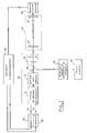
- two lasers 10 and 20 produce respective beams of radiation which are brought along a common path by a joining optic 31 in a known manner.
- a partial reflection separating plate 34 derives part of the common beam of the two lasers towards a detection and measurement device 70.
- the other part of the beam passes through a collimator 35, intended to adapt the characteristics of the beams coming from the lasers to the modes of the interferometer, before arriving at the interferometer 40, consisting of two partially reflecting plates 41 and 42. The spacing of these plates defines the distance to be measured.
- block 60 schematically illustrates the control of the frequencies of the two lasers 10 and 20 using the signals of the detector 50.
- the device 70 comprises a detector of an intermodulation type, from which there results a frequency component Fi-F 2 , measured by an electronic counter, and from which a computer 80 determines the distance between the blades 41 and 42 of the interferometer.
- the lasers used can be of many types. At the present time, carbon dioxide waveguide lasers are preferred, which are both single-mode, very powerful, and capable of a fairly wide frequency variation by action on the dimensions of the cavity. However, other longitudinal single-mode lasers with or without waveguide may also be suitable; it is advantageous that the lasers are also transverse single-mode, since the wave surface is then likely to facilitate detection.
- the sensor is fast, broadband and sensitive, while having a good quadratic response (light energy sensor).
- the fast detector Hg-Cd Te sold by the governmental Anonyme de Telecommunications, or else a diode of the MIM (metal-insulator-metal) type, or other detectors sensitive to the light frequencies concerned.
- the block 70 includes a preamplifier, such as the HP 84470 model and a counter such as the HP 5345 A, while the calculation unit 80 can be, for example, the HP 9825 A computer, all these items being sold by Hewlett-Packard.
- a preamplifier such as the HP 84470 model and a counter such as the HP 5345 A
- the calculation unit 80 can be, for example, the HP 9825 A computer, all these items being sold by Hewlett-Packard.
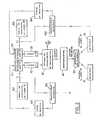
- a first embodiment of the invention will now be described, as regards the servo, with reference to FIG. 2.
- the two CO 2 waveguide lasers are joined as previously indicated, and their cavities are individually adjustable, for example using piezoelectric wedges, which makes it possible to vary their 'operating frequencies F 1 individually. and F 2 .
- This variation is controlled by electronic circuits 611 and 612 which act respectively on the lasers 10 and 20, in this case on their respective piezoelectric wedges.
- two reaction chains 641 and 642 control the base frequencies F 1 and F 2 of the two lasers 10 and 20, through the circuits 611 and 612.
- the base frequencies Fi and F 2 are subject to modulation at respective frequencies fi and f 2 , defined by the modulation signals which emanate from circuits 621 and 622.
- the frequencies of the two laser radiations thus vary symmetrically, preferably sinusoidally, around the central frequencies F 1 and F 2 .
- the modulation frequencies fi and f 2 can be equal.
- frequencies f 1 and f 2 are also applied to synchronous demodulator circuits 631 and 632, the outputs of which control the reaction chains 641 and 642, respectively.
- the purpose of the 631 and 632 synchronous demodulators is to synchronously detect the effect of the initial modulation of the lasers on the light transmitted by the Fabry-Pérot interferometer. (We will see below the arrangement of the associated photoelectric detectors).
- the signal from the synchronous detection is proportional to the first derivative of the transmitted light intensity with respect to the frequency of the light.
- These signals applied to the input of the reaction chains 641 and 642 therefore make it possible to adjust the central values Fi and F 2 of the laser radiation to obtain extremes of the intensities of light transmitted around these two frequencies.
- the servos can act on the frequencies Fi and F 2 to cancel the outputs of the synchronous demodulators 631 and 632.
- the optical separator 53 is used at the output of the interferometer 40, which supplies the two photoelectric detectors 51 and 52 respectively connected to the two synchronous demodulators 631 and 632 (FIG. 2).
- Another solution consists in multiplexing the modulation of lasers 10 and 20 over time.
- a single detector is connected to the output of the interferometer, and its output is demultiplexed by electronic gates to be switched alternatively to synchronous demodulators 631 and 632.
- Fig. 3 illustrates another, simpler solution.
- the two lasers are modulated at the same frequency f, but by signals in phase quadrature, noted f (0) and
- a single detector 50 is connected between the interferometer 40 and the two synchronous demodulators 631 and 632, the input of which is the same.
- These are the local quadrature signals f (0) and respectively applied to the two demodulators 631 and 632 which ensure the decoupling of the two laser radiations, so that the output of 631 represents the derivative of the light intensity transmitted around the frequency F 1 , and that of 632 the derivative of the intensity light transmitted around the frequency F 2 .
- the frequencies of the two laser radiations vary permanently around their central frequencies F 1 and F 2 . This variation is naturally found at the level of the AF signal transmitted to the measurement stages 70 and 80.
- Fig. 4 illustrates a preferred variant of the invention.
- the radiation from the two lasers 10 and 20 are made optically separable, preferably using two separate polarizations.
- the output of the interferometer 40 is brought to a beam splitter 53, in the two outputs supplying the two detectors 51 and 52.
- the modulation signal from the circuit 62 is brought into play.
- the length of the interferometer is modulated around its central value L, linked to the distance to be measured.
- the laser frequencies F 1 and F 2 are not modulated.
- the operation is the same as before: the two synchronous demodulators 631 and 632 are connected to the two reaction chains acting on the two laser frequencies, respectively, to obtain peaks of transmitted light.
- This variant is currently preferred because it only involves the amplitude-frequency response of the interferometer, while the first embodiment also involves the amplitude-frequency response of the lasers, because of their modulation.
- the detectors 50 or else 51 and 52 may be of the same type as the detector incorporated in the circuit 70.
- the electronic servo circuits are, for their part, provided for example with a loop interruption and with a manual control.
- the lasers are brought to two different modes of the interferometer manually, after which the servos are looped and follow the two peaks thus reached. Of course, one can also provide an automatic search for peaks.
- the invention allows the rapid and precise measurement of large parts and applies in particular to the shafts and bearings of turbines, to the parts used in the production of LNG tanks, to large machine tools and to their automatic control, or to the canopies of 'planes, for example.
Landscapes
- Physics & Mathematics (AREA)
- General Physics & Mathematics (AREA)
- Engineering & Computer Science (AREA)
- Automation & Control Theory (AREA)
- Optics & Photonics (AREA)
- Instruments For Measurement Of Length By Optical Means (AREA)
- Length Measuring Devices By Optical Means (AREA)
- Optical Radar Systems And Details Thereof (AREA)
- Measurement Of Optical Distance (AREA)
Claims (10)
Priority Applications (1)
| Application Number | Priority Date | Filing Date | Title |
|---|---|---|---|
| AT80401476T ATE4749T1 (de) | 1979-10-17 | 1980-10-16 | Verfahren und apparat zur abstandsmessung durch laserinterferometrie mit zwei wellenlaengen. |
Applications Claiming Priority (2)
| Application Number | Priority Date | Filing Date | Title |
|---|---|---|---|
| FR7925771A FR2468099A1 (fr) | 1979-10-17 | 1979-10-17 | Procede et appareil d'interferometrie laser a deux longueurs d'ondes |
| FR7925771 | 1979-10-17 |
Publications (2)
| Publication Number | Publication Date |
|---|---|
| EP0027763A1 EP0027763A1 (de) | 1981-04-29 |
| EP0027763B1 true EP0027763B1 (de) | 1983-09-21 |
Family
ID=9230752
Family Applications (1)
| Application Number | Title | Priority Date | Filing Date |
|---|---|---|---|
| EP80401476A Expired EP0027763B1 (de) | 1979-10-17 | 1980-10-16 | Verfahren und Apparat zur Abstandsmessung durch Laserinterferometrie mit zwei Wellenlängen |
Country Status (5)
| Country | Link |
|---|---|
| US (1) | US4492464A (de) |
| EP (1) | EP0027763B1 (de) |
| AT (1) | ATE4749T1 (de) |
| DE (1) | DE3064960D1 (de) |
| FR (1) | FR2468099A1 (de) |
Cited By (1)
| Publication number | Priority date | Publication date | Assignee | Title |
|---|---|---|---|---|
| DE4033253A1 (de) * | 1990-10-19 | 1992-04-23 | Hommelwerke Gmbh | Optisches interferometer |
Families Citing this family (19)
| Publication number | Priority date | Publication date | Assignee | Title |
|---|---|---|---|---|
| US4611915A (en) * | 1983-06-07 | 1986-09-16 | The United States Of America As Represented By The Secretary Of The Air Force | Absolute distance sensor |
| US4830486A (en) * | 1984-03-16 | 1989-05-16 | Goodwin Frank E | Frequency modulated lasar radar |
| US4593368A (en) * | 1984-06-04 | 1986-06-03 | Kollmorgen Technologies Corporation | Technique for measuring very small spacings |
| FR2592950B1 (fr) * | 1986-01-14 | 1988-01-29 | Sopelem | Dispositif optique de mesure de petits angles |
| DE3736772A1 (de) * | 1987-08-05 | 1989-05-11 | Bundesrep Deutschland | Laser-doppler-anemometer |
| JPH0198902A (ja) * | 1987-10-12 | 1989-04-17 | Res Dev Corp Of Japan | 光波干渉測長装置 |
| JPH0749923B2 (ja) * | 1989-05-31 | 1995-05-31 | 大日本スクリーン製造株式会社 | レーザ測長器のための単位変換装置 |
| US4995697A (en) * | 1989-09-07 | 1991-02-26 | The United States Of America As Represented By The Administrator Of The National Aeronautics And Space Administration | Fiber optic sensing system |
| FR2664603B1 (fr) * | 1990-07-10 | 1994-04-29 | Roquette Freres | Procede de permutation ionique d'amidons ionises et amidons ionises ainsi obtenus. |
| US5371587A (en) * | 1992-05-06 | 1994-12-06 | The Boeing Company | Chirped synthetic wavelength laser radar |
| US5430537A (en) * | 1993-09-03 | 1995-07-04 | Dynamics Research Corporation | Light beam distance encoder |
| WO2000043083A2 (en) | 1999-01-20 | 2000-07-27 | Schmidt Karl B | Apparatus for providing feedback to a user in connection with performing a movement task |
| DE19902455A1 (de) * | 1999-01-22 | 2000-08-10 | Bosch Gmbh Robert | Abstandsmeßverfahren und -vorrichtung |
| US6934035B2 (en) * | 2001-12-18 | 2005-08-23 | Massachusetts Institute Of Technology | System and method for measuring optical distance |
| US7557929B2 (en) | 2001-12-18 | 2009-07-07 | Massachusetts Institute Of Technology | Systems and methods for phase measurements |
| US7215413B2 (en) * | 2005-06-24 | 2007-05-08 | The Boeing Company | Chirped synthetic wave laser radar apparatus and methods |
| EP2182387A1 (de) | 2008-10-30 | 2010-05-05 | EADS Construcciones Aeronauticas, S.A. | Anzeigesystem und Verfahren für Auftankvorgänge |
| EP2806246B1 (de) * | 2013-05-24 | 2019-11-20 | Attocube Systems AG | Doppellaserinterferometer |
| CN106092514B (zh) * | 2015-04-28 | 2018-10-02 | 南京理工大学 | 基于双波长斐索干涉仪的光学非均匀性测量装置及方法 |
Family Cites Families (5)
| Publication number | Priority date | Publication date | Assignee | Title |
|---|---|---|---|---|
| NL6904621A (de) * | 1969-03-25 | 1970-09-29 | ||
| FR2051899A5 (de) * | 1969-07-01 | 1971-04-09 | Sud Aviation | |
| US3661464A (en) * | 1970-03-16 | 1972-05-09 | Jorway Corp | Optical interferometer |
| FR2245932A1 (en) * | 1973-06-15 | 1975-04-25 | Orszag Alain | Distance measuring interferometric instrument - has molecular laser for measuring distances of several hundred metres |
| US3970389A (en) * | 1974-02-14 | 1976-07-20 | Mendrin Michael J | Variable frequency interferometer |
-
1979
- 1979-10-17 FR FR7925771A patent/FR2468099A1/fr active Granted
-
1980
- 1980-10-16 DE DE8080401476T patent/DE3064960D1/de not_active Expired
- 1980-10-16 EP EP80401476A patent/EP0027763B1/de not_active Expired
- 1980-10-16 AT AT80401476T patent/ATE4749T1/de not_active IP Right Cessation
-
1984
- 1984-03-27 US US06/593,927 patent/US4492464A/en not_active Expired - Fee Related
Cited By (1)
| Publication number | Priority date | Publication date | Assignee | Title |
|---|---|---|---|---|
| DE4033253A1 (de) * | 1990-10-19 | 1992-04-23 | Hommelwerke Gmbh | Optisches interferometer |
Also Published As
| Publication number | Publication date |
|---|---|
| FR2468099A1 (fr) | 1981-04-30 |
| US4492464A (en) | 1985-01-08 |
| FR2468099B1 (de) | 1983-09-30 |
| ATE4749T1 (de) | 1983-10-15 |
| DE3064960D1 (en) | 1983-10-27 |
| EP0027763A1 (de) | 1981-04-29 |
Similar Documents
| Publication | Publication Date | Title |
|---|---|---|
| EP0027763B1 (de) | Verfahren und Apparat zur Abstandsmessung durch Laserinterferometrie mit zwei Wellenlängen | |
| EP0870180B1 (de) | Optisches bauelement zur polarisationsmodulation, und dessen verwendung in einem polarimeter oder ellipsometer | |
| JP3091840B2 (ja) | 高エネルギーレーザー焦点センサー | |
| FR2615279A1 (fr) | Capteur de deplacement a fibres optiques decalees | |
| WO2017108400A1 (fr) | Dispositif et procede de mesure de hauteur en presence de couches minces | |
| EP0406058A1 (de) | Vorrichtung zur Windgeschwindigkeitsmessung in mittleren Höhen | |
| JPH09119813A (ja) | フィルムの厚さ及び屈折率を測定するための方法及び装置 | |
| EP1346237B1 (de) | Laser-anemometer | |
| FR2516233A1 (fr) | Gyroscope a laser en anneau utilisant un detecteur de phase pour minimiser le verrouillage entre faisceaux | |
| JPH0972723A (ja) | フィルムの厚さと屈折率を測定するための測定方法及び測定装置 | |
| EP2405287B1 (de) | Vorrichtung zur Laserfernerkennung, und Interferometrieverfahren | |
| EP0237415B1 (de) | Vorrichtung zur spektralphotometrischen Ellipsometrie mit Verwendung optischer Fasern | |
| EP0846274B1 (de) | Optischer geschwindigkeitssensor | |
| EP0428702A1 (de) | Optoelektronische einrichtung zur messung einer physikalischen grösse über eine entfernung. | |
| EP0971203A1 (de) | Verfahren und Vorrichtung zur Messung der Dicke von transparenten Materialien | |
| WO1993004347A1 (fr) | Microcapteur a poutre vibrante compense en temperature | |
| EP2828635B1 (de) | System zur messung einer trennzone bei einem substrat | |
| FR2716722A1 (fr) | Système interférométrique de détection et de localisation de défauts réflecteurs de structures guidant la lumière. | |
| EP4078235A1 (de) | Kalibrierung eines lidar-systems | |
| WO2000009978A1 (fr) | Appareil de mesure de la longueur d'onde d'un faisceau lumineux | |
| EP0591911B1 (de) | Interferometer bestehend aus einer integrierten Anordnung und einem reflektierenden Teil, die durch eine Messzone voneinander getrennt sind | |
| FR3064349A1 (fr) | Dispositif et procede de reflectometrie a faible coherence a detection temps-frequence | |
| EP0450244B1 (de) | Detektionsvorrichtung mit optischen Fibern | |
| FR2632723A1 (fr) | Systeme de detection pour photometre | |
| EP0591912A2 (de) | Interferometer, bestehend aus einer integrierten Anordnung und einem Spiegel, die durch eine Messzone voneinander getrennt sind |
Legal Events
| Date | Code | Title | Description |
|---|---|---|---|
| PUAI | Public reference made under article 153(3) epc to a published international application that has entered the european phase |
Free format text: ORIGINAL CODE: 0009012 |
|
| AK | Designated contracting states |
Designated state(s): AT BE CH DE FR GB IT LU NL SE |
|
| 17P | Request for examination filed |
Effective date: 19810401 |
|
| ITF | It: translation for a ep patent filed |
Owner name: FUMERO BREVETTI S.N.C. |
|
| GRAA | (expected) grant |
Free format text: ORIGINAL CODE: 0009210 |
|
| STAA | Information on the status of an ep patent application or granted ep patent |
Free format text: STATUS: THE PATENT HAS BEEN GRANTED |
|
| AK | Designated contracting states |
Designated state(s): AT BE CH DE FR GB IT LI LU NL SE |
|
| REF | Corresponds to: |
Ref document number: 4749 Country of ref document: AT Date of ref document: 19831015 Kind code of ref document: T |
|
| PGFP | Annual fee paid to national office [announced via postgrant information from national office to epo] |
Ref country code: LU Payment date: 19831005 Year of fee payment: 4 |
|
| REF | Corresponds to: |
Ref document number: 3064960 Country of ref document: DE Date of ref document: 19831027 |
|
| PG25 | Lapsed in a contracting state [announced via postgrant information from national office to epo] |
Ref country code: LU Free format text: LAPSE BECAUSE OF NON-PAYMENT OF DUE FEES Effective date: 19831031 |
|
| PLBE | No opposition filed within time limit |
Free format text: ORIGINAL CODE: 0009261 |
|
| 26N | No opposition filed | ||
| PGFP | Annual fee paid to national office [announced via postgrant information from national office to epo] |
Ref country code: CH Payment date: 19841005 Year of fee payment: 5 |
|
| PGFP | Annual fee paid to national office [announced via postgrant information from national office to epo] |
Ref country code: DE Payment date: 19841008 Year of fee payment: 5 |
|
| PGFP | Annual fee paid to national office [announced via postgrant information from national office to epo] |
Ref country code: FR Payment date: 19841026 Year of fee payment: 5 |
|
| PGFP | Annual fee paid to national office [announced via postgrant information from national office to epo] |
Ref country code: SE Payment date: 19841231 Year of fee payment: 5 Ref country code: BE Payment date: 19841231 Year of fee payment: 5 |
|
| PGFP | Annual fee paid to national office [announced via postgrant information from national office to epo] |
Ref country code: AT Payment date: 19860922 Year of fee payment: 7 |
|
| PGFP | Annual fee paid to national office [announced via postgrant information from national office to epo] |
Ref country code: NL Payment date: 19871031 Year of fee payment: 8 |
|
| PG25 | Lapsed in a contracting state [announced via postgrant information from national office to epo] |
Ref country code: GB Effective date: 19881016 Ref country code: AT Effective date: 19881016 |
|
| PG25 | Lapsed in a contracting state [announced via postgrant information from national office to epo] |
Ref country code: SE Effective date: 19881017 |
|
| PG25 | Lapsed in a contracting state [announced via postgrant information from national office to epo] |
Ref country code: LI Effective date: 19881031 Ref country code: CH Effective date: 19881031 Ref country code: BE Effective date: 19881031 |
|
| BERE | Be: lapsed |
Owner name: ANVAR AGENCE NATIONALE DE VALORISATION DE LA RECH Effective date: 19881031 |
|
| PG25 | Lapsed in a contracting state [announced via postgrant information from national office to epo] |
Ref country code: NL Effective date: 19890501 |
|
| NLV4 | Nl: lapsed or anulled due to non-payment of the annual fee | ||
| PG25 | Lapsed in a contracting state [announced via postgrant information from national office to epo] |
Ref country code: FR Free format text: LAPSE BECAUSE OF NON-PAYMENT OF DUE FEES Effective date: 19890630 |
|
| REG | Reference to a national code |
Ref country code: CH Ref legal event code: PL |
|
| PG25 | Lapsed in a contracting state [announced via postgrant information from national office to epo] |
Ref country code: DE Effective date: 19890701 |
|
| GBPC | Gb: european patent ceased through non-payment of renewal fee | ||
| REG | Reference to a national code |
Ref country code: FR Ref legal event code: ST |
|
| EUG | Se: european patent has lapsed |
Ref document number: 80401476.9 Effective date: 19890614 |