EP0240732B1 - Schweisselement zum Verschweissen stumpfgestossener Rohre aus Kunststoff - Google Patents
Schweisselement zum Verschweissen stumpfgestossener Rohre aus Kunststoff Download PDFInfo
- Publication number
- EP0240732B1 EP0240732B1 EP87103165A EP87103165A EP0240732B1 EP 0240732 B1 EP0240732 B1 EP 0240732B1 EP 87103165 A EP87103165 A EP 87103165A EP 87103165 A EP87103165 A EP 87103165A EP 0240732 B1 EP0240732 B1 EP 0240732B1
- Authority
- EP
- European Patent Office
- Prior art keywords
- welding
- welding element
- annular disc
- saddle part
- heating wire
- Prior art date
- Legal status (The legal status is an assumption and is not a legal conclusion. Google has not performed a legal analysis and makes no representation as to the accuracy of the status listed.)
- Expired - Lifetime
Links
- 238000003466 welding Methods 0.000 title claims abstract description 72
- 229920003023 plastic Polymers 0.000 title claims abstract description 16
- 239000004033 plastic Substances 0.000 title claims abstract description 16
- 238000010438 heat treatment Methods 0.000 claims abstract description 44
- 238000001816 cooling Methods 0.000 claims abstract description 4
- 238000004804 winding Methods 0.000 claims description 32
- 239000000463 material Substances 0.000 claims description 9
- 239000004698 Polyethylene Substances 0.000 claims description 2
- -1 polyethylene Polymers 0.000 claims description 2
- 229920000573 polyethylene Polymers 0.000 claims description 2
- 238000000034 method Methods 0.000 description 4
- 239000011324 bead Substances 0.000 description 3
- 238000001746 injection moulding Methods 0.000 description 2
- 230000002093 peripheral effect Effects 0.000 description 2
- 238000004026 adhesive bonding Methods 0.000 description 1
- 230000015572 biosynthetic process Effects 0.000 description 1
- 239000002131 composite material Substances 0.000 description 1
- 230000000694 effects Effects 0.000 description 1
- 238000002844 melting Methods 0.000 description 1
- 230000008018 melting Effects 0.000 description 1
- 238000004023 plastic welding Methods 0.000 description 1
- 238000009417 prefabrication Methods 0.000 description 1
- 238000004080 punching Methods 0.000 description 1
- 229910000679 solder Inorganic materials 0.000 description 1
- 230000008719 thickening Effects 0.000 description 1
- 230000007704 transition Effects 0.000 description 1
- XLYOFNOQVPJJNP-UHFFFAOYSA-N water Substances O XLYOFNOQVPJJNP-UHFFFAOYSA-N 0.000 description 1
Images

Classifications
-
- B—PERFORMING OPERATIONS; TRANSPORTING
- B29—WORKING OF PLASTICS; WORKING OF SUBSTANCES IN A PLASTIC STATE IN GENERAL
- B29D—PRODUCING PARTICULAR ARTICLES FROM PLASTICS OR FROM SUBSTANCES IN A PLASTIC STATE
- B29D23/00—Producing tubular articles
- B29D23/001—Pipes; Pipe joints
- B29D23/003—Pipe joints, e.g. straight joints
- B29D23/005—Pipe joints, e.g. straight joints provided with electrical wiring
-
- B—PERFORMING OPERATIONS; TRANSPORTING
- B29—WORKING OF PLASTICS; WORKING OF SUBSTANCES IN A PLASTIC STATE IN GENERAL
- B29C—SHAPING OR JOINING OF PLASTICS; SHAPING OF MATERIAL IN A PLASTIC STATE, NOT OTHERWISE PROVIDED FOR; AFTER-TREATMENT OF THE SHAPED PRODUCTS, e.g. REPAIRING
- B29C65/00—Joining or sealing of preformed parts, e.g. welding of plastics materials; Apparatus therefor
- B29C65/02—Joining or sealing of preformed parts, e.g. welding of plastics materials; Apparatus therefor by heating, with or without pressure
- B29C65/34—Joining or sealing of preformed parts, e.g. welding of plastics materials; Apparatus therefor by heating, with or without pressure using heated elements which remain in the joint, e.g. "verlorenes Schweisselement"
- B29C65/3404—Joining or sealing of preformed parts, e.g. welding of plastics materials; Apparatus therefor by heating, with or without pressure using heated elements which remain in the joint, e.g. "verlorenes Schweisselement" characterised by the type of heated elements which remain in the joint
- B29C65/342—Joining or sealing of preformed parts, e.g. welding of plastics materials; Apparatus therefor by heating, with or without pressure using heated elements which remain in the joint, e.g. "verlorenes Schweisselement" characterised by the type of heated elements which remain in the joint comprising at least a single wire, e.g. in the form of a winding
-
- B—PERFORMING OPERATIONS; TRANSPORTING
- B29—WORKING OF PLASTICS; WORKING OF SUBSTANCES IN A PLASTIC STATE IN GENERAL
- B29C—SHAPING OR JOINING OF PLASTICS; SHAPING OF MATERIAL IN A PLASTIC STATE, NOT OTHERWISE PROVIDED FOR; AFTER-TREATMENT OF THE SHAPED PRODUCTS, e.g. REPAIRING
- B29C65/00—Joining or sealing of preformed parts, e.g. welding of plastics materials; Apparatus therefor
- B29C65/02—Joining or sealing of preformed parts, e.g. welding of plastics materials; Apparatus therefor by heating, with or without pressure
- B29C65/34—Joining or sealing of preformed parts, e.g. welding of plastics materials; Apparatus therefor by heating, with or without pressure using heated elements which remain in the joint, e.g. "verlorenes Schweisselement"
- B29C65/3468—Joining or sealing of preformed parts, e.g. welding of plastics materials; Apparatus therefor by heating, with or without pressure using heated elements which remain in the joint, e.g. "verlorenes Schweisselement" characterised by the means for supplying heat to said heated elements which remain in the join, e.g. special electrical connectors of windings
-
- B—PERFORMING OPERATIONS; TRANSPORTING
- B29—WORKING OF PLASTICS; WORKING OF SUBSTANCES IN A PLASTIC STATE IN GENERAL
- B29C—SHAPING OR JOINING OF PLASTICS; SHAPING OF MATERIAL IN A PLASTIC STATE, NOT OTHERWISE PROVIDED FOR; AFTER-TREATMENT OF THE SHAPED PRODUCTS, e.g. REPAIRING
- B29C65/00—Joining or sealing of preformed parts, e.g. welding of plastics materials; Apparatus therefor
- B29C65/02—Joining or sealing of preformed parts, e.g. welding of plastics materials; Apparatus therefor by heating, with or without pressure
- B29C65/34—Joining or sealing of preformed parts, e.g. welding of plastics materials; Apparatus therefor by heating, with or without pressure using heated elements which remain in the joint, e.g. "verlorenes Schweisselement"
- B29C65/3472—Joining or sealing of preformed parts, e.g. welding of plastics materials; Apparatus therefor by heating, with or without pressure using heated elements which remain in the joint, e.g. "verlorenes Schweisselement" characterised by the composition of the heated elements which remain in the joint
- B29C65/3476—Joining or sealing of preformed parts, e.g. welding of plastics materials; Apparatus therefor by heating, with or without pressure using heated elements which remain in the joint, e.g. "verlorenes Schweisselement" characterised by the composition of the heated elements which remain in the joint being metallic
-
- B—PERFORMING OPERATIONS; TRANSPORTING
- B29—WORKING OF PLASTICS; WORKING OF SUBSTANCES IN A PLASTIC STATE IN GENERAL
- B29C—SHAPING OR JOINING OF PLASTICS; SHAPING OF MATERIAL IN A PLASTIC STATE, NOT OTHERWISE PROVIDED FOR; AFTER-TREATMENT OF THE SHAPED PRODUCTS, e.g. REPAIRING
- B29C66/00—General aspects of processes or apparatus for joining preformed parts
- B29C66/01—General aspects dealing with the joint area or with the area to be joined
- B29C66/05—Particular design of joint configurations
- B29C66/10—Particular design of joint configurations particular design of the joint cross-sections
- B29C66/11—Joint cross-sections comprising a single joint-segment, i.e. one of the parts to be joined comprising a single joint-segment in the joint cross-section
- B29C66/112—Single lapped joints
-
- B—PERFORMING OPERATIONS; TRANSPORTING
- B29—WORKING OF PLASTICS; WORKING OF SUBSTANCES IN A PLASTIC STATE IN GENERAL
- B29C—SHAPING OR JOINING OF PLASTICS; SHAPING OF MATERIAL IN A PLASTIC STATE, NOT OTHERWISE PROVIDED FOR; AFTER-TREATMENT OF THE SHAPED PRODUCTS, e.g. REPAIRING
- B29C66/00—General aspects of processes or apparatus for joining preformed parts
- B29C66/01—General aspects dealing with the joint area or with the area to be joined
- B29C66/05—Particular design of joint configurations
- B29C66/10—Particular design of joint configurations particular design of the joint cross-sections
- B29C66/11—Joint cross-sections comprising a single joint-segment, i.e. one of the parts to be joined comprising a single joint-segment in the joint cross-section
- B29C66/114—Single butt joints
- B29C66/1142—Single butt to butt joints
-
- B—PERFORMING OPERATIONS; TRANSPORTING
- B29—WORKING OF PLASTICS; WORKING OF SUBSTANCES IN A PLASTIC STATE IN GENERAL
- B29C—SHAPING OR JOINING OF PLASTICS; SHAPING OF MATERIAL IN A PLASTIC STATE, NOT OTHERWISE PROVIDED FOR; AFTER-TREATMENT OF THE SHAPED PRODUCTS, e.g. REPAIRING
- B29C66/00—General aspects of processes or apparatus for joining preformed parts
- B29C66/01—General aspects dealing with the joint area or with the area to be joined
- B29C66/05—Particular design of joint configurations
- B29C66/10—Particular design of joint configurations particular design of the joint cross-sections
- B29C66/12—Joint cross-sections combining only two joint-segments; Tongue and groove joints; Tenon and mortise joints; Stepped joint cross-sections
- B29C66/122—Joint cross-sections combining only two joint-segments, i.e. one of the parts to be joined comprising only two joint-segments in the joint cross-section
- B29C66/1222—Joint cross-sections combining only two joint-segments, i.e. one of the parts to be joined comprising only two joint-segments in the joint cross-section comprising at least a lapped joint-segment
-
- B—PERFORMING OPERATIONS; TRANSPORTING
- B29—WORKING OF PLASTICS; WORKING OF SUBSTANCES IN A PLASTIC STATE IN GENERAL
- B29C—SHAPING OR JOINING OF PLASTICS; SHAPING OF MATERIAL IN A PLASTIC STATE, NOT OTHERWISE PROVIDED FOR; AFTER-TREATMENT OF THE SHAPED PRODUCTS, e.g. REPAIRING
- B29C66/00—General aspects of processes or apparatus for joining preformed parts
- B29C66/01—General aspects dealing with the joint area or with the area to be joined
- B29C66/05—Particular design of joint configurations
- B29C66/10—Particular design of joint configurations particular design of the joint cross-sections
- B29C66/12—Joint cross-sections combining only two joint-segments; Tongue and groove joints; Tenon and mortise joints; Stepped joint cross-sections
- B29C66/122—Joint cross-sections combining only two joint-segments, i.e. one of the parts to be joined comprising only two joint-segments in the joint cross-section
- B29C66/1224—Joint cross-sections combining only two joint-segments, i.e. one of the parts to be joined comprising only two joint-segments in the joint cross-section comprising at least a butt joint-segment
-
- B—PERFORMING OPERATIONS; TRANSPORTING
- B29—WORKING OF PLASTICS; WORKING OF SUBSTANCES IN A PLASTIC STATE IN GENERAL
- B29C—SHAPING OR JOINING OF PLASTICS; SHAPING OF MATERIAL IN A PLASTIC STATE, NOT OTHERWISE PROVIDED FOR; AFTER-TREATMENT OF THE SHAPED PRODUCTS, e.g. REPAIRING
- B29C66/00—General aspects of processes or apparatus for joining preformed parts
- B29C66/50—General aspects of joining tubular articles; General aspects of joining long products, i.e. bars or profiled elements; General aspects of joining single elements to tubular articles, hollow articles or bars; General aspects of joining several hollow-preforms to form hollow or tubular articles
- B29C66/51—Joining tubular articles, profiled elements or bars; Joining single elements to tubular articles, hollow articles or bars; Joining several hollow-preforms to form hollow or tubular articles
- B29C66/52—Joining tubular articles, bars or profiled elements
- B29C66/522—Joining tubular articles
- B29C66/5221—Joining tubular articles for forming coaxial connections, i.e. the tubular articles to be joined forming a zero angle relative to each other
-
- B—PERFORMING OPERATIONS; TRANSPORTING
- B29—WORKING OF PLASTICS; WORKING OF SUBSTANCES IN A PLASTIC STATE IN GENERAL
- B29C—SHAPING OR JOINING OF PLASTICS; SHAPING OF MATERIAL IN A PLASTIC STATE, NOT OTHERWISE PROVIDED FOR; AFTER-TREATMENT OF THE SHAPED PRODUCTS, e.g. REPAIRING
- B29C66/00—General aspects of processes or apparatus for joining preformed parts
- B29C66/50—General aspects of joining tubular articles; General aspects of joining long products, i.e. bars or profiled elements; General aspects of joining single elements to tubular articles, hollow articles or bars; General aspects of joining several hollow-preforms to form hollow or tubular articles
- B29C66/51—Joining tubular articles, profiled elements or bars; Joining single elements to tubular articles, hollow articles or bars; Joining several hollow-preforms to form hollow or tubular articles
- B29C66/52—Joining tubular articles, bars or profiled elements
- B29C66/522—Joining tubular articles
- B29C66/5229—Joining tubular articles involving the use of a socket
- B29C66/52291—Joining tubular articles involving the use of a socket said socket comprising a stop
- B29C66/52292—Joining tubular articles involving the use of a socket said socket comprising a stop said stop being internal
-
- F—MECHANICAL ENGINEERING; LIGHTING; HEATING; WEAPONS; BLASTING
- F16—ENGINEERING ELEMENTS AND UNITS; GENERAL MEASURES FOR PRODUCING AND MAINTAINING EFFECTIVE FUNCTIONING OF MACHINES OR INSTALLATIONS; THERMAL INSULATION IN GENERAL
- F16L—PIPES; JOINTS OR FITTINGS FOR PIPES; SUPPORTS FOR PIPES, CABLES OR PROTECTIVE TUBING; MEANS FOR THERMAL INSULATION IN GENERAL
- F16L47/00—Connecting arrangements or other fittings specially adapted to be made of plastics or to be used with pipes made of plastics
- F16L47/02—Welded joints; Adhesive joints
-
- B—PERFORMING OPERATIONS; TRANSPORTING
- B29—WORKING OF PLASTICS; WORKING OF SUBSTANCES IN A PLASTIC STATE IN GENERAL
- B29C—SHAPING OR JOINING OF PLASTICS; SHAPING OF MATERIAL IN A PLASTIC STATE, NOT OTHERWISE PROVIDED FOR; AFTER-TREATMENT OF THE SHAPED PRODUCTS, e.g. REPAIRING
- B29C66/00—General aspects of processes or apparatus for joining preformed parts
- B29C66/70—General aspects of processes or apparatus for joining preformed parts characterised by the composition, physical properties or the structure of the material of the parts to be joined; Joining with non-plastics material
- B29C66/71—General aspects of processes or apparatus for joining preformed parts characterised by the composition, physical properties or the structure of the material of the parts to be joined; Joining with non-plastics material characterised by the composition of the plastics material of the parts to be joined
-
- B—PERFORMING OPERATIONS; TRANSPORTING
- B29—WORKING OF PLASTICS; WORKING OF SUBSTANCES IN A PLASTIC STATE IN GENERAL
- B29C—SHAPING OR JOINING OF PLASTICS; SHAPING OF MATERIAL IN A PLASTIC STATE, NOT OTHERWISE PROVIDED FOR; AFTER-TREATMENT OF THE SHAPED PRODUCTS, e.g. REPAIRING
- B29C66/00—General aspects of processes or apparatus for joining preformed parts
- B29C66/80—General aspects of machine operations or constructions and parts thereof
- B29C66/81—General aspects of the pressing elements, i.e. the elements applying pressure on the parts to be joined in the area to be joined, e.g. the welding jaws or clamps
- B29C66/816—General aspects of the pressing elements, i.e. the elements applying pressure on the parts to be joined in the area to be joined, e.g. the welding jaws or clamps characterised by the mounting of the pressing elements, e.g. of the welding jaws or clamps
- B29C66/8167—Quick change joining tools or surfaces
-
- Y—GENERAL TAGGING OF NEW TECHNOLOGICAL DEVELOPMENTS; GENERAL TAGGING OF CROSS-SECTIONAL TECHNOLOGIES SPANNING OVER SEVERAL SECTIONS OF THE IPC; TECHNICAL SUBJECTS COVERED BY FORMER USPC CROSS-REFERENCE ART COLLECTIONS [XRACs] AND DIGESTS
- Y10—TECHNICAL SUBJECTS COVERED BY FORMER USPC
- Y10T—TECHNICAL SUBJECTS COVERED BY FORMER US CLASSIFICATION
- Y10T403/00—Joints and connections
- Y10T403/47—Molded joint
- Y10T403/477—Fusion bond, e.g., weld, etc.
-
- Y—GENERAL TAGGING OF NEW TECHNOLOGICAL DEVELOPMENTS; GENERAL TAGGING OF CROSS-SECTIONAL TECHNOLOGIES SPANNING OVER SEVERAL SECTIONS OF THE IPC; TECHNICAL SUBJECTS COVERED BY FORMER USPC CROSS-REFERENCE ART COLLECTIONS [XRACs] AND DIGESTS
- Y10—TECHNICAL SUBJECTS COVERED BY FORMER USPC
- Y10T—TECHNICAL SUBJECTS COVERED BY FORMER US CLASSIFICATION
- Y10T428/00—Stock material or miscellaneous articles
- Y10T428/21—Circular sheet or circular blank
- Y10T428/218—Aperture containing
Definitions
- the invention relates to a welding element for welding butt-butted pipes made of plastic, which is provided with a heating wire winding for electrical resistance heating and can be placed between the abutting pipe ends, which can be pressed against one another when the welding element is heated to the welding temperature, and after the heating has been switched off, are held together until the welded area is hardened by cooling, the welding element being designed as an annular disk, the outer diameter of which is approximately equal to the outer diameter of the tubes and the inner diameter of which is approximately equal to the nominal pipe diameter, and the heating wire winding runs spirally around the geometric center of the annular disk.
- a welding element of the aforementioned type is known from US-A-3 378 672.
- the known welding element is formed from a rectangular plastic strip with a heating wire embedded therein.
- the plastic tape is wound spirally or helically, so that the screw made of plastic tape has a disk-like shape. Such a disk-shaped screw can be placed between the butt-butted pipe ends to be connected.
- the heating wire embedded in the plastic of the plastic band forms when wound Plastic tape also has a spiral heating wire winding, which is used for electrical resistance heating.
- the ends of the heating wire winding must be accessible from the outside of the pipes in order to make the electrical connections.
- this requires an intersection from the inside to the outside.
- the inner end of the plastic tape with the heating wire embedded therein must cross the helical windings of the plastic tape, which leads to difficulties in butt welding. For example, an undesirable local thickening forms in the intersection area, which leads to an uneven mutual abutment of the parts to be welded to one another.
- the known welding element also has the disadvantage that, when the embedded heating wire winding is heated, the plastic material of the welding element can be melted.
- the pipe ends to be butted are not melted to the extent that a homogeneous and permanent welded connection is created.
- a welded connection with the known welding element thus does not even have the quality that can be achieved with conventional welding mirrors.
- EP-A-0 160 536 also specifies a welding element in the form of a disc-shaped ring, in which a spiral heating wire winding is placed on one side of the ring, with grooves being present which receive the wire.
- this welding element is only equipped with heating wire on a single ring side surface, and the problem of wire crossings does not result from the fact that the supply and discharge lines are each placed on the free second ring side surface.
- this design makes the known welding element unsuitable for butt welding.
- the grooves are closed again after the heating wire has been attached by applying a welding bar. After the grooves have been closed, the heating wire inserted therein is embedded in the welding element, so that melting of the pipe ends to be butted together is not possible.
- the invention has for its object to improve the butt welding of plastic pipes to the effect that an optimal quality of the weld is guaranteed with simplified handling.
- heating wire winding is placed on both ring side surfaces coming into contact with the pipe ends, starting on one ring side surface on the outer circumference, running inwards to the geometric center, passing there to the other ring side surface and then from the inside is returned to the outer circumference and that the two ring side surfaces of the ring disk have grooves defining the course of the wire, into which the wire can be inserted under clamping, as holding members for the heating wire winding.
- a heating wire winding is placed on both side surfaces of the ring washer, the heating wire being clamped in the grooves defining the course of the wire.
- the inventive two-sided attachment of the heating wire winding has the advantage that there is no disadvantageous crossing of the wire winding.
- the heating wire winding exposed on the outside of the ring side surface also has the advantage that not only the welding element itself but also the abutting pipe ends are plasticized when the welding temperature is reached, since the heating wire exposed on the ring side surfaces has contact with the pipe ends.
- the pipe ends can be aligned in a final position and are only pressed together, which can also be done manually if necessary.
- An annular disc can advantageously be placed between the pipe ends.
- the outer peripheral surface of the washer is flush with the surfaces of the pipe ends.
- the free cross-section of the pipes is only insignificantly reduced even after welding, since only a small bead forms on the weld joint when the pipe ends are pressed together.
- the heating wire When the welding current is applied, the heating wire is heated uniformly and thus the surfaces of the ring disk that are in contact with the pipe ends to be welded are brought uniformly to the welding temperature and the heat is passed on to the adjacent pipe ends. Overheated areas do not appear.
- the winding is free of crossings, since it begins in a spiral inwards, starting on one side of the ring disk, runs there to the other side of the ring disk and is then again guided in a spiral from the inside to the outside.
- the beginning and end of the wire placed spirally on the side of the ring protrude from the ring disk, so that they remain usable for connecting the welding current supply.
- the heating wire winding is held on the surfaces of the ring disk, the ring side surfaces, the ring side surfaces have molded-in holding members for the heating wire winding.
- Grooves which define the course of the wire can be provided as holding members, for example, into which the wire can be inserted with clamping.
- the heating wire winding can be applied simply by rotating the ring disk, the wire being fed continuously to the rotating ring disk and pressed into the groove of the ring disk to be loaded, which runs under a wire feed becomes.
- the annular disc consists of a material that can be plasticized when heated, preferably of the same plastic from which the pipes to be welded are also made.
- the ring disk can be inserted with particular advantage into a saddle part having the shape of a sleeve section.
- the saddle part can be placed in the area of the pipe ends of two pipes that are aligned with one another, the annular disc inserted into the saddle part then being inserted into the joint between the pipe ends as soon as the saddle part rests on the pipes that are aligned with one another.
- the saddle part thus fulfills the advantageous function of positioning the washer between the pipe ends to be welded together and holding it in this position until the pipe ends are pressed against one another and thus holding the washer clamped between them.
- the saddle part also fulfills the function of keeping the pipe ends to be connected in alignment, so that an undesired misalignment of the pipe ends cannot occur.
- the saddle part can accommodate contact elements with which the ends of the heating wire windings are connected on the ring disk.
- the connection to a welding unit that emits the welding current is therefore easy to use and reliable.
- the saddle part encloses the ring disk in a circumference greater than 180 °.
- the saddle part can thus act on the pipe ends to be connected to one another like a clamp, which holds the pipes properly positioned during the welding process. Additional holding devices for the pipes during the welding process are not necessary since the holding of the pipes is also taken over by the saddle part.
- the welding element is characterized in that the annular disk and the saddle part have connecting elements which can be brought into engagement with one another. This allows the ring disk to be manufactured separately from the saddle part, with the advantage that the winding of the ring disk with heating wire is easier. The completely wound ring disk can then be connected to the prepared saddle part to form a ready-to-use welding element.
- At least one projection radially projecting from the annular disk and at least one recess in the saddle part receiving the projection are provided as the connecting element. Recess and projection can be inserted into one another, so that the It is easy to assemble the ring washer and saddle part, there is no need to pay attention to special mutual alignment and positioning, because the parts only fit into one another if the projection and recess coincide.
- connection is preferably designed such that the projection protrudes through the recess and that edges of the projection protruding from the recess are connected to the saddle part.
- This connection can be made by gluing or welding. When welding, for example, a heated bar is pressed onto the protruding edge of the projection until it is plasticized, pressed wide and the connection between the projection and the saddle part is fully given after cooling.
- the saddle part Since the saddle part is intended to align and hold the pipe ends to be welded to one another without misalignment, its inner wall surfaces lie against the outer lateral surface of the pipe ends. Since the pipe ends are pressed against one another during welding, material that has become plastic emerges from the weld joint as a result of the heating and protrudes in a bead-like manner, as is usual in the butt welding process.
- the inner surface area of the saddle part has a groove which receives the peripheral edge of the annular disk and whose width is greater than the thickness of the annular disk. Plasticized material pressed out of the weld joint between the pipe ends can escape into this groove, so that a clean weld bead can form between the pipe ends.
- the material for the ring disk and the saddle part is preferably polyethylene, which material is common for pipes, in particular gas and water pipes.
- the washer and saddle can be made in a simple injection molding process be produced in large numbers. Since the dimensions of pipes are standardized, corresponding ring disks with saddle parts can easily be produced with suitable dimensions.
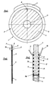
- FIG. 1 shows a front view of a disk 1 made of plastic by injection molding, the outer circular ring area of which forms ring side surfaces 2, 2a, can be covered with a heating wire winding which runs spirally around the geometric center 3 of the disk. After the heating wire winding has been attached, the hatched central region 4 of the disk is cut away, as a result of which an annular disk 5 with wound ring side surfaces 2, 2a remains.
- the edge of the disc is provided with a projection 7 in the upper region.
- the projection is used to attach the washer to a saddle part, which will be explained in more detail below.
- 2 shows a section through the pane 1. The same components are labeled with the same reference numbers. 2 shows the two ring side surfaces 2 and 2a of the ring disk 5 provided with heating wire windings.
- FIG. 3 shows that 5 grooves 8 are formed in the ring side surfaces 2 and 2a of the ring washer, which run spirally and correspond to the spiral laying of the heating wire winding. A heating wire 9 is inserted into the groove. The beginning of the wire 10 begins in the area of the outer circumference of the ring disk 5 and runs in a spiral in the plane of the ring side surface 2 until the opening 6 is reached.
- the opening is arranged so that it extends into the lowermost groove, so that the wire can be guided through the opening 6 to the opposite groove 8a and is returned to the outer circumference in a spiral following the grooves in the ring side surface 2a until the wire end 11 is freely available.
- a disc 1 wound in this way is then formed by punching out the central region 4 to form the annular disc 5.
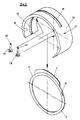
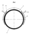
- the wound washer 5 is inserted into a saddle part, which is shown in section in Fig. 4 in a front view is.
- the saddle part 12 encloses the annular disc, as shown here, to a extent that is greater than 180 °.
- the washer is inserted into a groove 13 on the inner surface 14 of the saddle part, the projection 7 of the washer extending through the recess 15 of the saddle part.
- the saddle part has bores 16 and 17 indicated here, which can accommodate the free wire ends 10 and 11 when the washer is held in the saddle part, so that they protrude outwards from the saddle part.
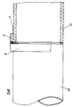
- the saddle part 12 is shown in a side view in section.
- the same components are labeled with the same reference numbers.
- Fig. 6 the wound washer 5 and the saddle part 12 is shown in an exploded view.
- the same components are labeled with the same reference numbers.
- Fig. 6 shows that in the bores 16 and 17 of the saddle part contact pins 18 and 19 can be inserted into which the free ends 10 and 11 of the wire winding can be inserted and fastened with solder drops 22 accordingly. Corresponding clamps of a welding unit can be connected to the contact pins.
- Fig. 7 shows a sectional view through a composite welding element, which consists of the washer 5 and the saddle part 12, wherein the projection 7 of the washer protrudes through the recess 15 in the saddle part.
- a heated welding bar can be pressed onto the edge of the projection 7 protruding from the recess 15, which plasticizes and broadly presses the edge, so that there is a firm connection between the washer and the saddle part.
- Fig. 7 also shows the arrangement of the contact pins 18 and 19, by means of which the connection of the heating wire winding on the washer 5 is ensured with a welding unit.
- the welding element designed in this way can, as shown in FIG. 8 is shown, are placed on two flush, butt-butted tubes 20 and 21.
- the washer 5 extends into the joint between the abutting pipe ends.
- the saddle part 12 fixes the pipe ends in the end position necessary for the welding.
- the welding element can remain on the pipe string after welding the pipe ends. However, measures can also be taken to release the connection between the saddle part and the ring disk melted by the welding process, so that the saddle part can be removed.
- the saddle part can also be made of other material, so that reuse is possible if necessary.
- the washer must in any case consist of weldable or heat-plastifiable material which can connect the pipe ends to be welded together.
Landscapes
- Engineering & Computer Science (AREA)
- Mechanical Engineering (AREA)
- General Engineering & Computer Science (AREA)
- Lining Or Joining Of Plastics Or The Like (AREA)
- Branch Pipes, Bends, And The Like (AREA)
Description
- Die Erfindung betrifft ein Schweißelement zum Verschweißen stumpfgestoßener Rohre aus Kunststoff, das mit einer Heizdrahtwicklung zur elektrischen Widerstandsbeheizung versehen ist und zwischen die aneinanderstoßenden Rohrenden legbar ist, die bei auf Schweißtemperatur erhitztem Schweißelement aneinander drückbar sind, und nach Abschalten der Beheizung solange aneinandergehalten bleiben, bis der verschweißte Bereich durch Erkalten erhärtet ist, wobei das Schweißelement als Ringscheibe ausgebildet ist, dessen Außendurchmesser etwa gleich dem Außendurchmesser der Rohre ist und dessen Innendurchmesser etwa gleich der Rohrnennweite ist und die Heizdrahtwicklung spiralförmig um das geometrische Zentrum der Ringscheibe läuft.
- Ein Schweißelement der vorbezeichneten Gattung ist nach der US-A-3 378 672 bekannt.
- Das bekannte Schweißelement ist gebildet aus einem im Profil rechteckigen Kunststoffband mit darin eingebettetem Heizdraht. Das Kunststoffband ist spiral- bzw. schneckenförmig aufgewickelt, so daß die Schnecke aus Kunststoffband eine scheibenförmige Gestalt hat. Eine solche scheibenförmige Schnecke läßt sich zwischen die miteinander zu verbindenden stumpfgestoßenen Rohrenden legen. Der im Kunststoff des Kunststoffbandes eingebettete Heizdraht bildet bei gewickeltem Kunststoffband ebenfalls eine spiralförmig verlaufende Heizdrahtwicklung, die zur elektrischen Widerstandsbeheizung genutzt wird.
- Bei einem Verschweißen stumpfgestoßener Rohre mit dem bekannten Schweißelement müssen die Enden der Heizdrahtwicklung vom Außenbereich der Rohre aus zugänglich sein, um die elektrischen Anschlüsse herzustellen. Bei dem bekannten Schweißelement erfordert dies eine Kreuzung von innen nach außen. Das innenliegende Ende des Kunststoffbandes mit dem darin eingebetteten Heizdraht muß die schneckenförmig gelegten Wicklungen des Kunststoffbandes kreuzen, was bei einer Stumpfschweißung zu Schwierigkeiten führt. Es bildet sich zum Beispiel im Kreuzungsbereich eine unerwünschte örtliche Verdickung aus, die zu einer ungleichmäßigen gegenseitigen Anlage der untereinander zu verschweißenden Teile führt. Darüber hinaus hat das bekannte Schweißelement auch den Nachteil, daß bei einer Erhitzung der eingebetteten Heizdrahtwicklung zwar das Kunststoffmaterial des Schweißelementes zum Schmelzen gebracht werden kann. Die aneinander zu stoßenden Rohrenden werden jedoch nicht soweit angeschmolzen, daß eine homogene und dauerhafte Schweißverbindung entsteht. Eine Schweißverbindung mit dem bekannten Schweißelement weist somit nicht einmal die Qualität auf, die mit herkömmlichen Schweißspiegeln erreichbar ist.
- Die EP-A-0 160 536 gibt ebenfalls ein Schweißelement in Form eines scheibenförmigen Ringes an, bei dem auf eine Ringseitenfläche eine spiralförmig verlaufende Heizdrahtwicklung gelegt ist, wobei Rillen vorhanden sind, die den Draht aufnehmen. Dieses Schweißelement ist jedoch nur an einer einzigen Ringseitenfläche mit Heizdraht ausgerüstet und es ergibt sich dadurch, daß die Zu- und Ableitungen jeweils auf die freie zweite Ringseitenfläche gelegt sind, das Problem der Drahtkreuzungen nicht. Gerade diese Ausbildung macht das bekannte Schweißelement jedoch ungeeignet für eine Stumpfschweißung. Darüber hinaus sind die Rillen nach Anbringen des Heizdrahtes durch Anlegen eines Schweißbalkens wieder verschlossen. Nach dem Verschließen der Rillen ist der darin eingelegte Heizdraht in das Schweißelement eingebettet, so daß ein Anschmelzen der aneinander zu stoßenden Rohrenden nicht möglich ist.
- Der Erfindung liegt die Aufgabe zugrunde, das Stumpfschweißen von Kunststoffrohren dahingehend zu verbessern, daß bei vereinfachter Handhabung eine optimale Qualität der Verschweißung gewährleistet ist.
- Diese Aufgabe ist erfindungsgemäß dadurch gelöst worden, daß die Heizdrahtwicklung auf beide mit den Rohrenden zur Anlage kommende Ringseitenflächen gelegt ist, wobei sie, auf einer Ringseitenfläche am Außenumfang beginnend, nach innen zum geometrischen Zentrum verläuft, dort auf die andere Ringseitenfläche durchläuft und dann von innen zum Außenumfang zurückgeführt ist und daß die beiden Ringseitenflächen der Ringscheibe den Verlauf des Drahtes vorgebende Rillen, in die der Draht unter Klemmung einlegbar ist, als Halteorgane für die Heizdrahtwicklung aufweisen.
- Bei dem erfindungsgemäßen Schweißelement ist auf beide Seitenflächen der Ringscheibe eine Heizdrahtwicklung gelegt, wobei der Heizdraht in den Verlauf des Drahtes vorgebende Rillen eingeklemmt ist. Durch das erfindungsgemäße beidseitige Anbringen der Heizdrahtwicklung stellt sich der Vorteil ein, daß eine nachteilige Kreuzung der Drahtwicklung entfällt. Die außen an der Ringseitenfläche freiliegende Heizdrahtwicklung hat darüber hinaus den Vorteil, daß nicht nur das Schweißelement selbst, sondern auch die aneinander stoßenden Rohrenden bei Erreichen der Schweißtemperatur plastifiziert sind, da der an den Ringseitenflächen freiliegende Heizdraht Kontakt mit den Rohrenden hat.
- Die Rohrenden können in eine endgültige Position ausgerichtet werden und werden lediglich aneinandergedrückt, was notfalls auch manuell ausgeführt werden kann.
- Eine Ringscheibe läßt sich mit Vorteil passend zwischen die Rohrenden setzen. Die äußere Umfangsfläche der Ringscheibe schließt bündig mit den Flächen der Rohrenden ab. Der freie Querschnitt der Rohre ist auch nach dem Verschweißen nur unwesentlich verkleinert, da sich durch das Aneinanderdrücken der Rohrenden lediglich ein kleiner Wulst an der Schweißfuge bildet.
- Bei Anlegen des Schweißstroms wird der Heizdraht gleichmäßig erwärmt und somit auch die mit den zu verschweißenden Rohrenden in Kontakt stehenden Oberflächen der Ringscheibe gleichmäßig auf Schweißtemperatur gebracht und die Wärme an die anliegenden Rohrenden weitergeleitet. Überhitzte Bereiche treten nicht auf. Die Wicklung ist kreuzungsfrei, da sie, auf einer Seite der Ringscheibe beginnend, spiralförmig nach innen verläuft, dort auf die andere Seite der Ringscheibe durchläuft und dann von innen nach außen wiederum spiralförmig geführt ist. Anfang und Ende des spiralförmig an die Ringseitenflächen gelegten Drahtes stehen von der Ringscheibe ab, so daß sie für den Anschluß der Schweißstromzuführung nutzbar bleiben.
- Damit die Heizdrahtwicklung an den Oberflächen der Ringscheibe, den Ringseitenflächen, festgehalten wird, weisen die Ringseitenflächen eingeformte Halteorgane für die Heizdrahtwicklung auf. Als Halteorgane können z.B. den Drahtverlauf vorgebende Rillen vorgesehen sein, in die der Draht unter Klemmung einlegbar ist. Die Heizdrahtwicklung kann einfach aufgebracht werden, indem die Ringscheibe gedreht wird, wobei der drehenden Ringscheibe der Draht fortlaufend zugeführt und in die jeweils zu beschickende, unter einer Drahtzuführung durchlaufende Rille der Ringscheibe eingedrückt wird.
- Selbstverständlich besteht die Ringscheibe aus einem bei Erwärmung plastifizierbaren Material, vorzugsweise aus dem gleichen Kunststoff, aus dem auch die zu verschweißenden Rohre gefertigt sind.
- Mit besonderem Vorteil kann die Ringscheibe in ein die Form eines Hülsenabschnittes aufweisendes Sattelteil eingesetzt sein. Das Sattelteil kann im Bereich der Rohrenden zweier miteinander fluchtender Rohre angesetzt werden, wobei die in das Sattelteil eingesetzte Ringscheibe dann in die Fuge zwischen den Rohrenden eingelegt ist, sobald das Sattelteil auf den miteinander fluchtenden Rohren aufliegt. Das Sattelteil erfüllt somit die vorteilhafte Funktion, die Ringscheibe zwischen den miteinander zu verschweißenden Rohrenden zu positionieren und in dieser Position zu halten, bis die Rohrenden aneinandergedrückt sind und somit die Ringscheibe zwischen sich klemmend halten. Gleichzeitig erfüllt das Sattelteil auch die Funktion, die miteinander zu verbindenden Rohrenden in einer Flucht zu halten, so daß ein nicht erwünschter Versatz der Rohrenden nicht auftreten kann.
- Weiterhin kann das Sattelteil Kontaktelemente aufnehmen, mit denen die Enden der Heizdrahtwicklungen auf der Ringscheibe verbunden sind. Der Anschluß an ein den Schweißstrom abgebendes Schweißaggregat ist dadurch einfach zu handhaben und betriebssicher.
- Ein Vorteil ergibt sich daraus, daß das Sattelteil die Ringscheibe in einem Umfang größer als 180° umschließt. Das Sattelteil kann dadurch auf die miteinander zu verbindenden Rohrenden wie eine Klemme wirken, welche die Rohre während des Schweißvorganges einwandfrei positioniert hält. Zusätzliche Haltevorrichtungen für die Rohre während des Verschweißvorganges sind nicht notwendig, da das Halten der Rohre von dem Sattelteil mit übernommen wird.
- Weiterhin zeichnet sich das Verschweißelement dadurch aus, daß die Ringscheibe und das Sattelteil gegenseitig in Eingriff bringbare Verbindungselemente aufweisen. Dadurch läßt sich die Ringscheibe separat vom Sattelteil fertigen, mit dem Vorteil, daß sich die Bewicklung der Ringscheibe mit Heizdraht einfacher gestaltet. Die fertig gewickelte Ringscheibe kann dann mit dem vorbereiteten Sattelteil zu einem einsatzbereiten Schweißelement verbunden werden.
- Als Verbindungselement ist wenigstens ein von der Ringscheibe radial abstehender Vorsprung und wenigsten eine den Vorsprung aufnehmende Ausnehmung in dem Sattelteil vorgesehen. Ausnehmung und Vorsprung lassen sich ineinanderstecken, so daß der Zusammenbau von Ringscheibe und Sattelteil einfach ist, auf besondere gegenseitige Ausrichtung und Positionierung braucht dabei nicht geachtet zu werden, denn die Teile passen nur dann ineinander, wenn Vorsprung und Ausnehmung miteinander kongruieren.
- Vorzugsweise ist die Verbindung so gestaltet, daß der Vorsprung durch die Ausnehmung ragt und daß aus der Ausnehmung vorstehende Ränder des Vorsprungs mit dem Sattelteil verbunden sind. Diese Verbindung kann durch Verkleben oder Verschweißen erfolgen. Beim Verschweißen wird beispielsweise ein erwärmter Balken auf den vorstehenden Rand des Vorsprungs gedrückt, bis dieser plastifiziert, breitgedrückt und die Verbindung zwischen Vorsprung und Sattelteil nach Erkalten voll gegeben ist.
- Da das Sattelteil die miteinander zu verschweißenden Rohrenden ohne Versatz ausrichten und halten soll, liegt es mit seinen Innenwandflächen an der äußeren Mantelfläche der Rohrenden an. Da während des Verschweißens die Rohrenden aneinandergedrückt werden, tritt durch die Erwärmung plastisch gewordenes Material aus der Schweißfuge aus und steht wulstartig vor, wie es bei Stumpfschweißverfahren üblich ist. Um trotz des engen Anliegens des Sattelteils an den Oberflächen der Rohrenden die Ausbildung eines Schweißwulstes zu ermöglichen, ist vorgesehen, daß die Innenmantelfläche des Sattelteils eine dem Umfangsrand der Ringscheibe aufnehmende Nut aufweist, deren Breite größer als die Dicke der Ringscheibe ist. In diese Nut kann plastifiziertes, aus der Schweißfuge zwischen den Rohrenden herausgedrücktes Material ausweichen, so daß sich ein sauberer Schweißwulst zwischen den Rohrenden ausbilden kann.
- Vorzugsweise ist der Werkstoff für die Ringscheibe und das Sattelteil Polyethylen, welcher Werkstoff für Rohre, insbesondere Gas- und Wasserrohre üblich ist.
- Ringscheibe und Sattelteil können in einem einfachen Spritzgußverfahren in großen Stückzahlen hergestellt werden. Da Abmessungen von Rohren genormt sind, können entsprechende Ringscheiben mit Sattelteilen ohne weiteres mit passenden Abmessungen hergestellt werden.
- Ein Ausführungsbeispiel der Erfindung, aus dem sich weitere erfinderische Merkmale ergeben, ist in der Zeichnung dargestellt. Es zeigen:
- Fig. 1
- eine Ansicht auf eine Scheibe im Stadium der Vorfertigung eines Schweißelements,
- Fig. 2
- eine Schnittansicht der Scheibe gemäß Fig. 1,
- Fig. 3
- die durch Einkreisung in Fig. 2 gekennzeichnete Einzelheit X in vergrößerndem Maßstab,
- Fig. 4
- eine Vorderansicht eines vorgefertigten Sattelteils im Schnitt,
- Fig. 5
- eine Seitenansicht des Sattelteils gemäß Fig. 4 im Schnitt
- Fig. 6
- verdeutlicht den Zusammenbau einer fertigen Ringscheibe mit dem Sattelteil zu einem Schweißelement,
- Fig. 7
- zeigt eine Ansicht eines zusammengebauten Schweißelements im Schnitt und
- Fig. 8
- eine Seitenansicht zweier stumpfgestoßener, miteinander zu verschweißender Rohrenden im Halbschnitt, mit angesetztem Schweißelement.
- In Fig. 1 ist eine Vorderansicht einer im Spritzgußverfahren aus Kunststoff gefertigten Scheibe 1 dargestellt, deren äußerer Kreisringbereich, der Ringseitenflächen 2, 2a bildet, mit einer um das geometrische Zentrum 3 der Scheibe spiralförmig verlaufenden Heizdrahtwicklung belegt werden kann. Nach Anbringen der Heizdrahtwicklung wird der schraffierte Zentralbereich 4 der Scheibe weggeschnitten, wodurch eine Ringscheibe 5 mit bewickelten Ringseitenflächen 2, 2a verbleibt.
- Im Übergangsbereich zwischen wegzuschneidendem zentralen Scheibenbereich 4 und der Ringseitenfläche 2 ist eine Durchbrechung 6 angeordnet, welche ermöglicht, den Draht der Wicklung von der hier sichbaren Ringseitenfläche 2 der Ringscheibe 5 auf die gegenüberliegende Ringseitenfläche 2a der Rihgscheibe zu führen und dort die Bewicklung dann von innen nach außen fortzusetzen.
- Im oberen Bereich ist der Rand der Scheibe mit einem Vorsprung 7 versehen. Der Vorsprung dient zur Befestigung der Ringscheibe an einem nachstehend noch näher erläuterten Sattelteil.
- In Fig. 2 ist ein Schnitt durch die Scheibe 1 dargestellt. Gleiche Bauteile sind mit gleichen Bezugszahlen bezeichnet. Fig. 2 läßt die beiden mit Heizdrahtwicklungen versehenen Ringseitenflächen 2 und 2a der Ringscheibe 5 erkennen.
- In Fig. 3 ist die durch Einkreisung in Fig. 2 gekennzeichnete Einzelheit X in vergrößerndem Maßstab dargestellt. Gleiche Bauteile sind wieder mit gleichen Bezugszahlen bezeichnet. Fig. 3 läßt erkennen, daß in die Ringseitenflächen 2 und 2a der Ringscheibe 5 Rillen 8 eingeformt sind, die spiralförmig verlaufen und der spiralförmigen Verlegung der Heizdrahtwicklung entsprechen. In die Rille ist ein Heizdraht 9 eingelegt. Der Drahtanfang 10 beginnt im Bereich des Außenumfangs der Ringscheibe 5 und verläuft spiralförmig in der Ebene der Ringseitenfläche 2, bis der Durchbruch 6 erreicht ist. Der Durchbruch ist so angeordnet, daß er sich bis in die unterste Rille erstreckt, so daß der Draht durch den Durchbruch 6 zur gegenüberliegenden Rille 8a geführt werden kann und in einer den Rillen in der Ringseitenfläche 2a folgenden Spirale zum Außenumfang zurückgeführt wird, bis das Drahtende 11 frei zur Verfügung steht. Eine derart bewickelte Scheibe 1 wird anschließend durch Ausstanzen des Zentralbereichs 4 zur Ringscheibe 5 ausgebildet.
- Die bewickelte Ringscheibe 5 wird in ein Sattelteil eingesetzt, das in Fig. 4 in einer Vorderansicht im Schnitt dargestellt ist. Das Sattelteil 12 umschließt die Ringscheibe, wie es hier dargestellt ist, in einem Umfang, der größer ist als 180°. Die Ringscheibe wird in eine Nut 13 an der Innenfläche 14 des Sattelteils eingelegt, wobei sich der Vorsprung 7 der Ringscheibe durch die Ausnehmung 15 des Sattelteils erstreckt. Das Sattelteil weist hier angedeutete Bohrungen 16 und 17 auf, die bei im Sattelteil gehaltener Ringscheibe die freien Drahtenden 10 und 11 aufnehmen können, so daß diese nach außen aus dem Sattelteil vorstehen.
- In Fig. 5 ist das Sattelteil 12 in einer Seitenansicht im Schnitt dargestellt. Gleiche Bauteile sind mit gleichen Bezugszahlen bezeichnet.
- In Fig. 6 ist in einer Explosionsdarstellung noch einmal die bewickelte Ringscheibe 5 und das Sattelteil 12 dargestellt. Gleiche Bauteile sind mit gleichen Bezugszahlen bezeichnet. Fig. 6 läßt erkennen, daß in die Bohrungen 16 und 17 des Sattelteils Kontaktstifte 18 und 19 steckbar sind, in die die freien Enden 10 und 11 der Drahtbewicklung einsteckbar und mit Löttropfen 22 entsprechend befestigt werden können. An die Kontaktstifte sind entsprechende Klemmen eines Schweißaggregats anschließbar.
- Fig. 7 zeigt eine Schnittansicht durch ein zusammengesetztes Schweißelement, das aus Ringscheibe 5 und Sattelteil 12 besteht, wobei der Vorsprung 7 der Ringscheibe durch die Ausnehmung 15 im Sattelteil vorsteht. Auf den aus der Ausnehmung 15 vorragenden Rand des Vorsprungs 7 kann ein erhitzter Schweißbalken gedrückt werden, der den Rand plastifiziert und breitdrückt, so daß eine feste Verbindung zwischen Ringscheibe und Sattelteil gegeben ist. Fig. 7 läßt auch die Anordnung der Kontaktstifte 18 und 19 erkennen, mittels welcher die Verbindung der Heizdrahtwicklung auf der Ringscheibe 5 mit einem Schweißaggregat gewährleistet ist.
- Das derart ausgebildete Schweißelement kann, wie es in Fig. 8 dargestellt ist, auf zwei miteinander fluchtende, stumpfgestoßene Rohre 20 und 21 gesetzt werden. Die Ringscheibe 5 erstreckt sich dabei in die Fuge zwischen den aneinanderstoßenden Rohrenden. Das Sattelteil 12 fixiert die Rohrenden in der für die Verschweißung notwendigen Endstellung.
- Das Schweißelement kann nach dem Schweißen der Rohrenden an dem Rohrstrang verbleiben. Es können jedoch auch Maßnahmen getroffen werden, um die Verbindung zwischen Sattelteil und durch den Schweißvorgang zerschmolzener Ringscheibe zu lösen, so daß das Sattelteil abgenommen werden kann.
- Das Sattelteil kann auch aus anderem Werkstoff gefertigt werden, so daß gegebenenfalls eine Wiederverwendung möglich ist. Die Ringscheibe muß in jedem Fall aus verschweißbarem, bzw. durch Wärmeeinwirkung plastifizierbarem Material bestehen, welches die miteinander zu verschweißenden Rohrenden verbinden kann.
Claims (9)
- Schweißelement zum Verschweißen Stumpfgestoßener Rohre aus Kunststoff, das mit einer Heizdrahtwicklung zur elektrischen Widerstandsbeheizung versehen ist und zwischen die aneinanderstoßenden Rohrenden legbar ist, die bei auf Schweißtemperatur erhitztem Schweißelement aneinander drückbar sind, und nach Abschalten der Beheizung solange aneinandergehalten bleiben, bis der verschweißte Bereich durch Erkalten erhärtet ist, wobei das Schweißelement als Ringscheibe ausgebildet ist, dessen Außendurchmesser etwa gleich dem Außendurchmesser der Rohre ist und dessen Innendurchmesser etwa gleich der Rohrnennweite ist und die Heizdrahtwicklung spiralförmig um das geometrische Zentrum der Ringscheibe läuft,
dadurch gekennzeichnet,
daß die Heizdrahtwicklung auf beide mit den Rohrenden (20,21) zur Anlage kommende Ringseitenflächen (2,2a) gelegt ist, wobei sie, auf einer Ringseitenfläche (2) am Außenumfang beginnend, nach innen zum geometrischen Zentrum verläuft, dort auf die andere Ringseitenfläche (2a) durchläuft und dann von innen zum Außenumfang zurückgeführt ist
und daß die beiden Ringseitenflächen (2,2a) der Ringscheibe (5) den Verlauf des Drahtes (9) vorgebende Rillen (8), in die der Draht (9) unter Klemmung einlegbar ist, als Halteorgane für die Heizdrahtwicklung aufweisen. - Schweißelement nach Anspruch 1, dadurch gekennzeichnet, daß die Ringscheibe (5) in ein die Form eines Hülsenabschnittes aufweisendes Sattelteil (12) eingesetzt ist.
- Schweißelement nach einem der Ansprüche 1 und 2, dadurch gekennzeichnet, daß die Enden (10,11) der Heizdrahtwicklungen auf der Ringscheibe (5) mit an dem Sattelteil (12) angeordneten Kontaktelementen (18,19) verbunden sind.
- Schweißelement nach einem der Ansprüche 1 bis 3, dadurch gekennzeichnet, daß das Sattelteil (12) die Ringscheibe (5) in einem Umfang größer als 180° umschließt.
- Schweißelement nach einem der Ansprüche 1 bis 4, dadurch gekennzeichnet, daß die Ringscheibe (5) und das Sattelteil (12) gegenseitig in Eingriff bringbare Verbindungselemente aufweisen.
- Schweißelement nach Anspruch 5, dadurch gekennzeichnet, daß als Verbindungselement wenigstens ein von der Ringscheibe (5) radial abstehender Vorsprung (7) und wenigstens eine den Vorsprung (7) aufnehmende Ausnehmung (15) in dem Sattelteil (12) vorgesehen ist.
- Schweißelement nach Anspruch 6, dadurch gekennzeichnet, daß der Vorsprung (7) durch die Ausnehmung (15) ragt und daß aus der Ausnehmung (15) vorstehende Ränder des Vorsprunges (7) mit dem Sattelteil (12) verbunden sind.
- Schweißelement nach einem der Ansprüche 1 bis 7, dadurch gekennzeichnet, daß die Innenmantelfläche (14) des Sattelteil (12) eine den Umfangsrand der Ringscheibe (5) aufnehmende Nut (13) aufweist, deren Breite größer als die Dicke der Ringscheibe (5) ist.
- Schweißelement nach einem der Ansprüche 1 bis 8, dadurch gekennzeichnet, daß der Werkstoff für Ringscheibe (5) und Sattelteil (12) Polyethylen ist.
Priority Applications (1)
| Application Number | Priority Date | Filing Date | Title |
|---|---|---|---|
| AT87103165T ATE95113T1 (de) | 1986-04-04 | 1987-03-05 | Schweisselement zum verschweissen stumpfgestossener rohre aus kunststoff. |
Applications Claiming Priority (2)
| Application Number | Priority Date | Filing Date | Title |
|---|---|---|---|
| DE19863611192 DE3611192A1 (de) | 1986-04-04 | 1986-04-04 | Verfahren zum verschweissen stumpfgestossener rohre aus kunststoff und schweisselement zur durchfuehrung des verfahrens |
| DE3611192 | 1986-04-04 |
Publications (3)
| Publication Number | Publication Date |
|---|---|
| EP0240732A2 EP0240732A2 (de) | 1987-10-14 |
| EP0240732A3 EP0240732A3 (en) | 1990-01-31 |
| EP0240732B1 true EP0240732B1 (de) | 1993-09-29 |
Family
ID=6297846
Family Applications (1)
| Application Number | Title | Priority Date | Filing Date |
|---|---|---|---|
| EP87103165A Expired - Lifetime EP0240732B1 (de) | 1986-04-04 | 1987-03-05 | Schweisselement zum Verschweissen stumpfgestossener Rohre aus Kunststoff |
Country Status (6)
| Country | Link |
|---|---|
| US (1) | US4851647A (de) |
| EP (1) | EP0240732B1 (de) |
| JP (1) | JPS631526A (de) |
| AT (1) | ATE95113T1 (de) |
| DE (2) | DE3611192A1 (de) |
| ES (1) | ES2047479T3 (de) |
Families Citing this family (15)
| Publication number | Priority date | Publication date | Assignee | Title |
|---|---|---|---|---|
| US5104468A (en) * | 1984-11-13 | 1992-04-14 | Riesselmann & Sohn | Method of producing a molded connection piece and method for joining tube with molded connection piece |
| NL8403462A (nl) * | 1984-11-13 | 1986-06-02 | Arie De Jong | Werkwijze voor het vervaardigen van een verbindingsvormstuk, in het bijzonder aanboorzadel en een volgens de werkwijze vervaardigd verbindingsvormstuk. |
| US5407514A (en) * | 1988-02-03 | 1995-04-18 | E. O. Butts Consultants Ltd. | Method for welding thermoplastic materials |
| JPH01124475U (de) * | 1988-02-17 | 1989-08-24 | ||
| GB8903223D0 (en) * | 1989-02-13 | 1989-03-30 | Du Pont Uk | Adjustable pipe bend with electrofusion facility |
| CH685814A5 (de) * | 1992-07-02 | 1995-10-13 | Fischer Georg Rohrleitung | Verfahren zum Verschweissen von rohrförmigen Teilen und ein Schweisselement zur Durchführung des Verfahrens. |
| US5494318A (en) * | 1993-04-29 | 1996-02-27 | Butts; Nicholas E. | Secondary containment system |
| GB2284179A (en) * | 1993-11-30 | 1995-05-31 | Uponor Aldyl Ltd | Electrofusion coupling element |
| WO1997001433A1 (en) * | 1995-06-28 | 1997-01-16 | Raymond Allan Goldsmid | Element for fusion welding plastics |
| GB2304073B (en) * | 1995-08-04 | 1999-06-16 | Uponor Ltd | Electrofusion element |
| US5736715A (en) * | 1996-03-19 | 1998-04-07 | Thermacor Process, Inc. | Method of forming pressure testable joint between insulated pipes using split sleeve arrangement |
| US6142483A (en) * | 1998-09-21 | 2000-11-07 | The United States Of America As Represented By The Administrator Of The National Aeronautics And Space Administration | Gasket assembly for sealing mating surfaces |
| US6840545B2 (en) * | 2001-10-22 | 2005-01-11 | Bernd Schulte-Ladbeck | Welded flange connection |
| DE102004023338A1 (de) * | 2004-05-12 | 2005-12-15 | Gwc Gas-Water-Valves-Components Gmbh | Heizvorrichtung zum Verschweißen von mindestens zwei aus einem Kunststoffmaterial bestehenden Gegenständen |
| US8741091B2 (en) * | 2012-04-26 | 2014-06-03 | Richard Hardy | Method for thermoplastic welding and welded composite structures |
Family Cites Families (16)
| Publication number | Priority date | Publication date | Assignee | Title |
|---|---|---|---|---|
| DD1161A (de) * | ||||
| DE7121715U (de) * | 1971-09-02 | Mannesmann Ag | Widerstandsheizelement zum Ver schweißen von Gegenstanden aus thermo plastischem Kunststoff | |
| US2744655A (en) * | 1953-09-22 | 1956-05-08 | Vnuk Josef | Lined container and closure therefor |
| DE1055305B (de) * | 1954-05-26 | 1959-04-16 | Ramsay Olaf St George | Verbindungsteil aus thermoplastischem Material in Form einer Muffe, eines T-Stueckesoder L-Stueckes |
| CH336980A (de) * | 1955-09-16 | 1959-03-15 | Fischer Ag Georg | Verfahren zum Zusammenschweissen von Rohrleitungselementen aus Kunststoff |
| US3378672A (en) * | 1966-03-18 | 1968-04-16 | Susquehanna Corp | Insulated, electrical resistance wire and welding sleeve made therefrom |
| DE1629221B2 (de) * | 1966-06-10 | 1972-12-21 | Wegener, Willy, Dipl.-Ing., 5100 Aachen | Schweißspiegel zum Stumpfschweißen von Rohren und Behältern aus thermoplastischem Kunststoff |
| CH507081A (de) * | 1969-04-09 | 1971-05-15 | Gebert & Cie | Verbindungsmuffe zum Verschweissen von Kunststoffrohren |
| JPS5150375A (de) * | 1974-10-30 | 1976-05-01 | Furukawa Electric Co Ltd | |
| FR2353381A1 (fr) * | 1976-06-03 | 1977-12-30 | Pont A Mousson | Procede d'assemblage par soudure de tubes plastiques et raccord pour un tel assemblage |
| US4313053A (en) * | 1980-01-02 | 1982-01-26 | Von Roll A.G. | Welding sleeve of thermoplastic material |
| MC1446A1 (fr) * | 1981-07-01 | 1982-12-06 | Innovation Tech Innotec | Derivation electrosoudable pour canalisation en materiau thermoplastique |
| FR2519578A1 (fr) * | 1981-07-01 | 1983-07-18 | Sam Innovation Tech | Dispositif en matiere plastique pour realiser une perforation dans un element sous-jacent en matiere plastique, procede de fabrication d'un tel dispositif et sa mise en oeuvre pour realiser des derivations de canalisations |
| GB8410765D0 (en) * | 1984-04-27 | 1984-06-06 | Glynwed Tubes & Fittings | Fusion pad |
| EP0170844B1 (de) * | 1984-08-08 | 1988-01-20 | Georg Fischer Aktiengesellschaft | Anbohrformstück aus schweissbarem Kunstoff |
| US4689108A (en) * | 1985-11-04 | 1987-08-25 | Gte Government Systems Corporation | Apparatus for assembling electrochemical batteries and similar articles |
-
1986
- 1986-04-04 DE DE19863611192 patent/DE3611192A1/de not_active Ceased
-
1987
- 1987-03-05 ES ES87103165T patent/ES2047479T3/es not_active Expired - Lifetime
- 1987-03-05 AT AT87103165T patent/ATE95113T1/de not_active IP Right Cessation
- 1987-03-05 EP EP87103165A patent/EP0240732B1/de not_active Expired - Lifetime
- 1987-03-05 DE DE87103165T patent/DE3787557D1/de not_active Expired - Fee Related
- 1987-04-02 JP JP62079842A patent/JPS631526A/ja active Pending
-
1988
- 1988-08-01 US US07/226,545 patent/US4851647A/en not_active Expired - Fee Related
Also Published As
| Publication number | Publication date |
|---|---|
| US4851647A (en) | 1989-07-25 |
| EP0240732A2 (de) | 1987-10-14 |
| DE3787557D1 (de) | 1993-11-04 |
| DE3611192A1 (de) | 1987-10-15 |
| JPS631526A (ja) | 1988-01-06 |
| EP0240732A3 (en) | 1990-01-31 |
| ES2047479T3 (es) | 1994-03-01 |
| ATE95113T1 (de) | 1993-10-15 |
Similar Documents
| Publication | Publication Date | Title |
|---|---|---|
| EP0240732B1 (de) | Schweisselement zum Verschweissen stumpfgestossener Rohre aus Kunststoff | |
| DE2724981C3 (de) | Schweißring zur Verbindung von Kunststoff rohren | |
| DE68909209T2 (de) | Verstellbarer Rohrbogen mit Elektroschweisseinrichtung. | |
| DE69024402T2 (de) | Elektroschweissmuffen | |
| EP0170845B1 (de) | Anbohrformstück zum Anschluss einer Abzweigleitung | |
| EP0035750A2 (de) | Schweissverbindung für Kunststoffrohre | |
| EP1756464B1 (de) | Verbindungsanordnung, insbesondere zum kraftschlüssigen anbinden von mindestens einem faserverbund-bauteil an ein weiteres bauteil | |
| EP0076460A1 (de) | Schweissverbindung für Kunststoffrohre | |
| EP0531750A2 (de) | Verfahren zum Verschweissen von aus thermoplastischem Kunststoff bestehenden Rohren | |
| EP0093328B1 (de) | Anschluss-Formstück | |
| EP0619176A2 (de) | Verfahren zum Verschweissen von aus thermoplastischem Kunststoff bestehenden Rohrstücken | |
| DE68914996T3 (de) | Verfahren und vorrichtung zur verbindung von zwei rohrförmigen kunststofferzeugnissen. | |
| DE4224680A1 (de) | Verfahren zum Verschweissen von rohrförmigen Teilen und ein Schweisselement zur Durchführung des Verfahrens | |
| EP3428097B1 (de) | Spule aus thermoplastischem material und verfahren zu ihrer herstellung | |
| EP0711948B1 (de) | Schweissmuffe zum Verbinden von Kunststoffrohrteilen | |
| DE9107311U1 (de) | Schweißmuffe | |
| DE19612279C2 (de) | Gehäuse, insbesondere Fassungsgehäuse für Glühlampen mit Schraubsockel sowie Verfahren zur Herstellung eines derartigen Gehäuses und Vorrichtungen zur Durchführung des Verfahrens | |
| EP0431288A2 (de) | Kugelhahn | |
| EP0305462B1 (de) | Vorrichtung zum verschweissen rohrförmiger kunststoffteile | |
| DE4214279C2 (de) | Verbindungselement zum Verschweißen von Rohren | |
| DE2431962C2 (de) | Rotor für einen induktiven Meßfühler und Verfahren zu seiner Herstellung | |
| DE4012297C1 (en) | Branch for plastics pipe - has saddle with electric heater to melt thermoplastics material to make welded joint | |
| EP3298316B1 (de) | Flanschverbindung für bauteile aus kunststoff, insbesondere für rohrförmige bauteile aus kunststoff | |
| EP0089638A2 (de) | Durchgangskupplung für Rohrleitungen oder Schläuche | |
| EP0204145A1 (de) | Verbindungsteil zum Verschweissen von Rohren |
Legal Events
| Date | Code | Title | Description |
|---|---|---|---|
| PUAI | Public reference made under article 153(3) epc to a published international application that has entered the european phase |
Free format text: ORIGINAL CODE: 0009012 |
|
| AK | Designated contracting states |
Kind code of ref document: A2 Designated state(s): AT BE CH DE ES FR GB GR IT LI LU NL SE |
|
| PUAL | Search report despatched |
Free format text: ORIGINAL CODE: 0009013 |
|
| AK | Designated contracting states |
Kind code of ref document: A3 Designated state(s): AT BE CH DE ES FR GB GR IT LI LU NL SE |
|
| 17P | Request for examination filed |
Effective date: 19900613 |
|
| 17Q | First examination report despatched |
Effective date: 19910610 |
|
| GRAA | (expected) grant |
Free format text: ORIGINAL CODE: 0009210 |
|
| AK | Designated contracting states |
Kind code of ref document: B1 Designated state(s): AT BE CH DE ES FR GB GR IT LI LU NL SE |
|
| REF | Corresponds to: |
Ref document number: 95113 Country of ref document: AT Date of ref document: 19931015 Kind code of ref document: T |
|
| REF | Corresponds to: |
Ref document number: 3787557 Country of ref document: DE Date of ref document: 19931104 |
|
| ITF | It: translation for a ep patent filed | ||
| ET | Fr: translation filed | ||
| GBT | Gb: translation of ep patent filed (gb section 77(6)(a)/1977) |
Effective date: 19940113 |
|
| REG | Reference to a national code |
Ref country code: GR Ref legal event code: FG4A Free format text: 3010319 |
|
| REG | Reference to a national code |
Ref country code: ES Ref legal event code: FG2A Ref document number: 2047479 Country of ref document: ES Kind code of ref document: T3 |
|
| PGFP | Annual fee paid to national office [announced via postgrant information from national office to epo] |
Ref country code: NL Payment date: 19940331 Year of fee payment: 8 Ref country code: LU Payment date: 19940331 Year of fee payment: 8 Ref country code: GB Payment date: 19940331 Year of fee payment: 8 Ref country code: FR Payment date: 19940331 Year of fee payment: 8 Ref country code: AT Payment date: 19940331 Year of fee payment: 8 |
|
| PGFP | Annual fee paid to national office [announced via postgrant information from national office to epo] |
Ref country code: BE Payment date: 19940401 Year of fee payment: 8 |
|
| PGFP | Annual fee paid to national office [announced via postgrant information from national office to epo] |
Ref country code: SE Payment date: 19940406 Year of fee payment: 8 |
|
| PGFP | Annual fee paid to national office [announced via postgrant information from national office to epo] |
Ref country code: DE Payment date: 19940412 Year of fee payment: 8 |
|
| PGFP | Annual fee paid to national office [announced via postgrant information from national office to epo] |
Ref country code: ES Payment date: 19940418 Year of fee payment: 8 |
|
| PGFP | Annual fee paid to national office [announced via postgrant information from national office to epo] |
Ref country code: GR Payment date: 19940427 Year of fee payment: 8 |
|
| PGFP | Annual fee paid to national office [announced via postgrant information from national office to epo] |
Ref country code: CH Payment date: 19940503 Year of fee payment: 8 |
|
| EPTA | Lu: last paid annual fee | ||
| PLBE | No opposition filed within time limit |
Free format text: ORIGINAL CODE: 0009261 |
|
| STAA | Information on the status of an ep patent application or granted ep patent |
Free format text: STATUS: NO OPPOSITION FILED WITHIN TIME LIMIT |
|
| 26N | No opposition filed | ||
| EAL | Se: european patent in force in sweden |
Ref document number: 87103165.4 |
|
| PG25 | Lapsed in a contracting state [announced via postgrant information from national office to epo] |
Ref country code: LU Free format text: LAPSE BECAUSE OF NON-PAYMENT OF DUE FEES Effective date: 19950305 Ref country code: GB Effective date: 19950305 Ref country code: AT Effective date: 19950305 |
|
| PG25 | Lapsed in a contracting state [announced via postgrant information from national office to epo] |
Ref country code: SE Effective date: 19950306 Ref country code: ES Free format text: LAPSE BECAUSE OF NON-PAYMENT OF DUE FEES Effective date: 19950306 |
|
| PG25 | Lapsed in a contracting state [announced via postgrant information from national office to epo] |
Ref country code: LI Effective date: 19950331 Ref country code: CH Effective date: 19950331 Ref country code: BE Effective date: 19950331 |
|
| BERE | Be: lapsed |
Owner name: RIESSELMANN & SOHN Effective date: 19950331 |
|
| PG25 | Lapsed in a contracting state [announced via postgrant information from national office to epo] |
Ref country code: GR Free format text: THE PATENT HAS BEEN ANNULLED BY A DECISION OF A NATIONAL AUTHORITY Effective date: 19950930 |
|
| PG25 | Lapsed in a contracting state [announced via postgrant information from national office to epo] |
Ref country code: NL Effective date: 19951001 |
|
| GBPC | Gb: european patent ceased through non-payment of renewal fee |
Effective date: 19950305 |
|
| PG25 | Lapsed in a contracting state [announced via postgrant information from national office to epo] |
Ref country code: FR Free format text: LAPSE BECAUSE OF NON-PAYMENT OF DUE FEES Effective date: 19951130 |
|
| REG | Reference to a national code |
Ref country code: CH Ref legal event code: PL Ref country code: GR Ref legal event code: MM2A Free format text: 3010319 |
|
| NLV4 | Nl: lapsed or anulled due to non-payment of the annual fee |
Effective date: 19951001 |
|
| PG25 | Lapsed in a contracting state [announced via postgrant information from national office to epo] |
Ref country code: DE Effective date: 19951201 |
|
| EUG | Se: european patent has lapsed |
Ref document number: 87103165.4 |
|
| REG | Reference to a national code |
Ref country code: FR Ref legal event code: ST |
|
| REG | Reference to a national code |
Ref country code: ES Ref legal event code: FD2A Effective date: 19990201 |
|
| PG25 | Lapsed in a contracting state [announced via postgrant information from national office to epo] |
Ref country code: IT Free format text: LAPSE BECAUSE OF NON-PAYMENT OF DUE FEES;WARNING: LAPSES OF ITALIAN PATENTS WITH EFFECTIVE DATE BEFORE 2007 MAY HAVE OCCURRED AT ANY TIME BEFORE 2007. THE CORRECT EFFECTIVE DATE MAY BE DIFFERENT FROM THE ONE RECORDED. Effective date: 20050305 |