EP0240536B1 - Method and apparatus for thermal treatment - Google Patents
Method and apparatus for thermal treatment Download PDFInfo
- Publication number
- EP0240536B1 EP0240536B1 EP86905950A EP86905950A EP0240536B1 EP 0240536 B1 EP0240536 B1 EP 0240536B1 EP 86905950 A EP86905950 A EP 86905950A EP 86905950 A EP86905950 A EP 86905950A EP 0240536 B1 EP0240536 B1 EP 0240536B1
- Authority
- EP
- European Patent Office
- Prior art keywords
- smelt
- pipe
- thermal treatment
- dividing wall
- decomposition products
- Prior art date
- Legal status (The legal status is an assumption and is not a legal conclusion. Google has not performed a legal analysis and makes no representation as to the accuracy of the status listed.)
- Expired - Lifetime
Links
Images

Classifications
-
- C—CHEMISTRY; METALLURGY
- C10—PETROLEUM, GAS OR COKE INDUSTRIES; TECHNICAL GASES CONTAINING CARBON MONOXIDE; FUELS; LUBRICANTS; PEAT
- C10B—DESTRUCTIVE DISTILLATION OF CARBONACEOUS MATERIALS FOR PRODUCTION OF GAS, COKE, TAR, OR SIMILAR MATERIALS
- C10B19/00—Heating of coke ovens by electrical means
-
- C—CHEMISTRY; METALLURGY
- C10—PETROLEUM, GAS OR COKE INDUSTRIES; TECHNICAL GASES CONTAINING CARBON MONOXIDE; FUELS; LUBRICANTS; PEAT
- C10B—DESTRUCTIVE DISTILLATION OF CARBONACEOUS MATERIALS FOR PRODUCTION OF GAS, COKE, TAR, OR SIMILAR MATERIALS
- C10B49/00—Destructive distillation of solid carbonaceous materials by direct heating with heat-carrying agents including the partial combustion of the solid material to be treated
- C10B49/14—Destructive distillation of solid carbonaceous materials by direct heating with heat-carrying agents including the partial combustion of the solid material to be treated with hot liquids, e.g. molten metals
-
- C—CHEMISTRY; METALLURGY
- C10—PETROLEUM, GAS OR COKE INDUSTRIES; TECHNICAL GASES CONTAINING CARBON MONOXIDE; FUELS; LUBRICANTS; PEAT
- C10B—DESTRUCTIVE DISTILLATION OF CARBONACEOUS MATERIALS FOR PRODUCTION OF GAS, COKE, TAR, OR SIMILAR MATERIALS
- C10B53/00—Destructive distillation, specially adapted for particular solid raw materials or solid raw materials in special form
Definitions
- the invention concerns an apparatus for thermal treatment of materials/substances which can be pumped or blown, particularly for the pyrolysis of waste products, where the material/ substance is pumped or blown into a heat chamber with a high temperature smelt, preferably a metal smelt, and where the heat chamber receives the thermal energy required from the electrical discharge between electrodes.
- a high temperature smelt preferably a metal smelt
- a range of chemical compounds are extremely stable or have stable decomposition products. Most of these compounds can however be broken down into their separate chemical components by maintaining the initial materials at a high temperature for a long period of time. This can be exemplified by the destruction of various types of waste, from for instance the production of plastics.
- pyrolysis plants with metal baths where the substance which is to be thermally processed or destructed is fed into the metal bath and heated by and in it by means of electrodes with an electrical discharge over the metal bath. Methods such as this will not produce high enough temperatures or long enough exposure for the most difficult thermal processes, such as the destruction of matter.
- the object of the invention is to provide an apparatus forthe thermal treatment of substances which can be pumped or blown, where a predetermined high temperature and sufficient exposure in the heated zone is obtained for a given substance. Another object is finding an apparatus where thermal treatment can be carried out without the addition of an oxidizing agent and which in a simple manner allows the collection of the gases and the other products of pyrolysis connected with the thermal treatment.
- the temperature is in the region of 5000°-12000°K, and the material to be destructed is forced to pass through this area. Lengthy exposure at a high temperature is ensured by forcing the products of the thermal treatment/pyrolysis in the vicinity of the electrodes to pass through a smelting bath which contributes to a final catalytic decomposition of extremely stable organic compounds.
- Thermal treatment with the apparatus according to the invention is possible without the addition of oxidizing agents. This reduces the amount of gas which has to be treated. Any valuable elements in the residual gas will consequently be more concentrated and in an easier utilised form than was previously found in combustion processes.
- the products or pyrolysis will contain carbon (Carbon Black) and smaller quantities of halogenides which can be filtered off from the gas.
- the gas may usually consist of 60-96% HCI, 1-30% CO, 1-5% H 2 as well as 2-8% N 2 all calculated on the basis of weight.
- Such a gas mixture is a suitable starting point for the production of technical hydrochloric acid using an existing method.
- the materials which are to be subjected to thermal treatment may contain heavy metals.
- the metal bath must consequently be refined in known manner from time to time to catch the heavy metals in a slag smelt.
- Some types of organic materials such as dioxines and polychlorinated biphenyls are difficult to destruct entirely by combustion processes alone, as the temperature should be in the region of 1200-1800°C for complete destruction.
- the method and apparatus according to the invention facilitate the destruction of such materials without the addition of combustibles at the same time as the destruction temperature can be selected independently of the combustible value of the material. This will result in less gas being produced than is the case with anyother method known.
- the pair of electrodes 15-16 constitute a unit and can be shaped as described in Norwegian Patent No. 141.183.
- Other heat sources based on electrodes can also be used providing they produce sufficiently high temperatures and where the electrodes can be built into a chamber where the exhaust gases from the combustion unit are forced to rise through a metal bath.
- the upper part of the electrode tube 15 is attached to a lower electrode holder 17 to which a coolant, preferably water, and electric current are supplied through a combined coolant and electric conductor 18.
- a coolant preferably water
- the coaxially-located electrode rod 16 is attached to the upper electrode holder 19 which has a combined supply of coolant and electric current 20.
- the upper electrode holder 19, is electrically insulated from the lower electrode holder 17 and vice versa.
- the upper electrode holder can be equipped with a device which can continuously displace the central electrode rod in an axial direction in relation to the outer electrode tube. This is not illustrated in Fig. 1.
- a device which can continuously displace the central electrode rod in an axial direction in relation to the outer electrode tube. This is not illustrated in Fig. 1.
- one or more supply conduits are led.
- the example shows two of these supply conduits, 22 and 23, which supply the material which is to be thermically treated and are supplied from a feed pipe 24.
- the feed pipe 24 can be linked to a dosage unit which pumps or blows controlled amounts of the substance into the annular space. Following the introduction of this matter, a gas zone will be formed in the lower part of the annular space 21 in the electrode tube 15.
- This gas zone will extend into the metal bath 12 and will be kept heated by the electrical discharge at the end of the electrodes. Thermal treatment such as the destruction of the material which has been fed in will commence in this area. The gas supplied and the gas generated by the heating will recede from the bottom of the metal bath 12 and flow up the outer side of the electrode tube 15.
- a pipe 25 has been located under the lid 13 with its free end 26 lowered into the metal bath to spread the discharged gas in a larger part of the metal bath 12. Furthermore, this allows longer contact time between the material and the hot metal bath.
- the free end 26 creates an annular space 27 around the electrode tube 15. From this annular space there are radial openings 28, for example four out from the pipe 25 in the metal bath.
- the mean specific weight of the metal bath will be reduced in the bubble region compared with the metal smelt without bubbles. This difference in density results in setting the metal bath into circulation, leading to increased contact time between the gas and the smelt.
- the metal spray is reduced by fitting the outlet for the products of pyrolysis through the connection pipe 14 with a stop plate 29 located on a central support 30.
- the intimate mixture of gas and smelt given by the pipe end 26 can also be achieved by other configurations.
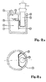
- One such design is exemplified in Figs. 2A and 2B, which illustrate a sealed thermically insulated receptacle or container 31 for a metal smelt 32.
- the combustion unit 35 and the supply conduits for the material to be thermically treated have been described above in connection with Fig. 1. However, in this configuration the combustion unit is located in a gas-tight chamber 36.
- the chamber 36 may be a part of the container 31 separated from the rest of the container with a vertical dividing wall 37 that is lowered into the metal smelt 32. There are gaps 38 in the dividing wall 37 which ensure the circulation of gas and smelt in the receptacle 31.
- the chamber 36 is gas-tight, the decomposition products from the combustion unit 35 are forced through the gaps 38 in the dividing wall 37 since the outlet for gas 34 is located outside the chamber 36.
- the chamber 36 and the combustion unit 35 can be located in different parts of the receptacle. There are a number of other usable configurations for the dividing wall than the one illustrated here.
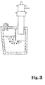
- Fig. 3 illustrates a third embodiment with a non- perforated dividing wall. More detailed information about materials and dimensions are not indicated, since these are considerations which have to be scientifically determined and adjusted to the various application areas.
- the configurations shown can be modified in a variety of ways.
- the electrode combustion unit described can be replaced by another type of electrode system where the pipe 25 is mounted on the electrode tube 15 to spread and increase the duration of the gas in the metal bath, and where the "mammoth pump" principle as it is frequently termed can either be excluded or made more extensive.
- the intimate mixture between the gas and the smelt which is the result of the skirt 26 can also be achieved by using other configurations.
- One example of such is shown in Fig. 2.
Landscapes
- Chemical & Material Sciences (AREA)
- Engineering & Computer Science (AREA)
- Oil, Petroleum & Natural Gas (AREA)
- Materials Engineering (AREA)
- Organic Chemistry (AREA)
- Combustion & Propulsion (AREA)
- Manufacture And Refinement Of Metals (AREA)
- Vertical, Hearth, Or Arc Furnaces (AREA)
- Processing Of Solid Wastes (AREA)
- Control Of Heat Treatment Processes (AREA)
- Heat Treatments In General, Especially Conveying And Cooling (AREA)
Applications Claiming Priority (2)
| Application Number | Priority Date | Filing Date | Title |
|---|---|---|---|
| NO853714 | 1985-09-23 | ||
| NO853714A NO157876C (no) | 1985-09-23 | 1985-09-23 | Fremgangsmaate og apparat for gjennomfoering av varmebehandling. |
Publications (2)
| Publication Number | Publication Date |
|---|---|
| EP0240536A1 EP0240536A1 (en) | 1987-10-14 |
| EP0240536B1 true EP0240536B1 (en) | 1990-05-16 |
Family
ID=19888492
Family Applications (1)
| Application Number | Title | Priority Date | Filing Date |
|---|---|---|---|
| EP86905950A Expired - Lifetime EP0240536B1 (en) | 1985-09-23 | 1986-09-19 | Method and apparatus for thermal treatment |
Country Status (5)
| Country | Link |
|---|---|
| US (1) | US4787320A (no) |
| EP (1) | EP0240536B1 (no) |
| DE (1) | DE3671283D1 (no) |
| NO (1) | NO157876C (no) |
| WO (1) | WO1987001792A1 (no) |
Families Citing this family (33)
| Publication number | Priority date | Publication date | Assignee | Title |
|---|---|---|---|---|
| US4960675A (en) * | 1988-08-08 | 1990-10-02 | Midwest Research Institute | Hydrogen ion microlithography |
| USRE35219E (en) * | 1988-09-14 | 1996-04-30 | Marine Shale Processors, Inc. | Apparatus for using hazardous waste to form non-hazardous aggregate |
| US5167919A (en) * | 1990-03-15 | 1992-12-01 | Wagner Anthony S | Waste treatment and metal reactant alloy composition |
| DE4211164C2 (de) * | 1992-03-31 | 1995-02-16 | Mannesmann Ag | Verfahren und Vorrichtung zum Behandeln von riesel- oder fließfähigem Material |
| US5095828A (en) * | 1990-12-11 | 1992-03-17 | Environmental Thermal Systems, Corp. | Thermal decomposition of waste material |
| US5143000A (en) * | 1991-05-13 | 1992-09-01 | Plasma Energy Corporation | Refuse converting apparatus using a plasma torch |
| DE4130416C1 (no) * | 1991-09-10 | 1992-12-10 | Thermoselect Ag, Vaduz, Li | |
| EP0520086B2 (de) * | 1991-06-18 | 1999-06-30 | Thermoselect Aktiengesellschaft | Verfahren zur Nutzbarmachung von Entsorgungsgütern aller Art |
| US5133267A (en) * | 1991-10-01 | 1992-07-28 | Marine Shale Processors, Inc. | Method and apparatus for using hazardous waste to form non-hazardous aggregate |
| CH686764A8 (de) * | 1994-09-29 | 1996-08-15 | Von Roll Umwelttechnik Ag | Verfahren zur Aufbereitung von festen Rückständen aus Müllverbrennungsanlagen und Vorrichtung zur Durchführung des Verfahrens. |
| CH688325A5 (de) * | 1994-11-25 | 1997-07-31 | Holderbank Financ Glarus | Verfahren zur Aufbereitung von festen Rueckstaenden aus Muellverbrennungsanlagen und Vorrichtung zur Drchfuehrung des Verfahrens. |
| US6227126B1 (en) | 1999-01-15 | 2001-05-08 | Clean Technologies, International Corporation | Molten metal reactor and treatment method for treating gaseous materials and materials which include volatile components |
| EP1201935A1 (en) | 2000-10-26 | 2002-05-02 | SONY-WEGA PRODUKTIONS GmbH | Fastening means |
| US6717026B2 (en) * | 2001-02-27 | 2004-04-06 | Clean Technologies International Corporation | Molten metal reactor utilizing molten metal flow for feed material and reaction product entrapment |
| IL168286A (en) * | 2005-04-28 | 2009-09-22 | E E R Env Energy Resrc Israel | Plasma torch for use in a waste processing chamber |
| US7752983B2 (en) * | 2006-06-16 | 2010-07-13 | Plasma Waste Recycling, Inc. | Method and apparatus for plasma gasification of waste materials |
| CN102989564B (zh) * | 2012-12-10 | 2014-09-17 | 湖南农业大学 | 一种家用食品垃圾处理机 |
| US11939477B2 (en) | 2014-01-30 | 2024-03-26 | Monolith Materials, Inc. | High temperature heat integration method of making carbon black |
| US10100200B2 (en) | 2014-01-30 | 2018-10-16 | Monolith Materials, Inc. | Use of feedstock in carbon black plasma process |
| US10138378B2 (en) | 2014-01-30 | 2018-11-27 | Monolith Materials, Inc. | Plasma gas throat assembly and method |
| US10370539B2 (en) | 2014-01-30 | 2019-08-06 | Monolith Materials, Inc. | System for high temperature chemical processing |
| BR112016017429B1 (pt) | 2014-01-31 | 2022-10-04 | Monolith Materials, Inc | Maçarico de plasma |
| CN113171740A (zh) | 2015-02-03 | 2021-07-27 | 巨石材料公司 | 炭黑生成系统 |
| BR112017016692A2 (pt) | 2015-02-03 | 2018-04-10 | Monolith Materials, Inc. | método e aparelho para resfriamento regenerativo |
| MX2018001259A (es) | 2015-07-29 | 2018-04-20 | Monolith Mat Inc | Aparato y método de diseño de energía eléctrica para soplete de plasma cc. |
| WO2017044594A1 (en) | 2015-09-09 | 2017-03-16 | Monolith Materials, Inc. | Circular few layer graphene |
| CN108352493B (zh) | 2015-09-14 | 2022-03-08 | 巨石材料公司 | 由天然气制造炭黑 |
| WO2017190015A1 (en) * | 2016-04-29 | 2017-11-02 | Monolith Materials, Inc. | Torch stinger method and apparatus |
| US11149148B2 (en) | 2016-04-29 | 2021-10-19 | Monolith Materials, Inc. | Secondary heat addition to particle production process and apparatus |
| EP3592810A4 (en) | 2017-03-08 | 2021-01-27 | Monolith Materials, Inc. | SYSTEMS AND METHODS FOR THE PRODUCTION OF CARBON PARTICLES WITH HEAT TRANSFER GAS |
| CA3060576A1 (en) | 2017-04-20 | 2018-10-25 | Monolith Materials, Inc. | Carbon particles with low sulfur, ash and grit impurities |
| CA3074220A1 (en) | 2017-08-28 | 2019-03-07 | Monolith Materials, Inc. | Systems and methods for particle generation |
| WO2019084200A1 (en) | 2017-10-24 | 2019-05-02 | Monolith Materials, Inc. | PARTICULAR SYSTEMS AND METHODS |
Citations (1)
| Publication number | Priority date | Publication date | Assignee | Title |
|---|---|---|---|---|
| WO1980000509A1 (en) * | 1978-08-21 | 1980-03-20 | Western Electric Co | Control techniques for annealing semiconductors |
Family Cites Families (7)
| Publication number | Priority date | Publication date | Assignee | Title |
|---|---|---|---|---|
| SE371651C (sv) * | 1973-03-30 | 1976-12-06 | Asea Ab | Sett och anordning for smeltreduktion |
| SE416656B (sv) * | 1979-04-12 | 1981-01-26 | Boliden Ab | Forfarande for utvinning av olja och/eller gas ur kolhaltiga material |
| JPS5682317A (en) * | 1979-12-08 | 1981-07-06 | Daido Steel Co Ltd | Processing method of refuse |
| WO1982000509A1 (en) * | 1980-07-25 | 1982-02-18 | I Faeldt | A method and an apparatus for thermal decomposition of stable compounds |
| CA1173784A (en) * | 1981-07-30 | 1984-09-04 | William H. Gauvin | Transferred-arc plasma reactor for chemical and metallurgical applications |
| CA1225441A (en) * | 1984-01-23 | 1987-08-11 | Edward S. Fox | Plasma pyrolysis waste destruction |
| GB2189508B (en) * | 1985-08-16 | 1990-12-05 | Bruss Ti Kirova | Method of treating molten metal and means for effecting the same |
-
1985
- 1985-09-23 NO NO853714A patent/NO157876C/no unknown
-
1986
- 1986-09-19 DE DE8686905950T patent/DE3671283D1/de not_active Expired - Fee Related
- 1986-09-19 US US07/053,851 patent/US4787320A/en not_active Expired - Fee Related
- 1986-09-19 WO PCT/NO1986/000066 patent/WO1987001792A1/en active IP Right Grant
- 1986-09-19 EP EP86905950A patent/EP0240536B1/en not_active Expired - Lifetime
Patent Citations (1)
| Publication number | Priority date | Publication date | Assignee | Title |
|---|---|---|---|---|
| WO1980000509A1 (en) * | 1978-08-21 | 1980-03-20 | Western Electric Co | Control techniques for annealing semiconductors |
Also Published As
| Publication number | Publication date |
|---|---|
| WO1987001792A1 (en) | 1987-03-26 |
| NO157876C (no) | 1988-06-01 |
| NO853714L (no) | 1987-03-24 |
| EP0240536A1 (en) | 1987-10-14 |
| US4787320A (en) | 1988-11-29 |
| DE3671283D1 (de) | 1990-06-21 |
| NO157876B (no) | 1988-02-22 |
Similar Documents
| Publication | Publication Date | Title |
|---|---|---|
| EP0240536B1 (en) | Method and apparatus for thermal treatment | |
| CA1209092A (en) | Method and apparatus for the decomposition of hazardous materials and the like | |
| US5809911A (en) | Multi-zone waste processing reactor system | |
| JP4048025B2 (ja) | 廃棄物、特に放射性廃棄物を焼却し且つガラス化する方法と装置 | |
| US4351734A (en) | Spark cell ozone generator | |
| EP0625869B1 (en) | Method for the melting, combustion or incineration of materials and apparatus therefor | |
| US20090093666A1 (en) | Vitrification Furnace With Dual Heating Means | |
| JPH03178981A (ja) | プラズマ反応装置 | |
| JPH07171543A (ja) | 坩堝内で廃棄物を灰化及びガラス化する方法 | |
| CA3160763A1 (en) | Plasma generator | |
| CN101616867A (zh) | 碳热法 | |
| US3706662A (en) | Non-polluting waste reducer and method | |
| JP2002503328A (ja) | 高温廃棄物処理の方法およびシステム | |
| US9376334B2 (en) | Method and device for treating wastes by means of injection into an immersed plasma | |
| KR100296495B1 (ko) | 수소산소 혼합가스 발생장치 | |
| JPH07509556A (ja) | 現場における生物有害廃棄物の処分システム | |
| EP1399284B1 (en) | Plasma arc treatment method using a dual mode plasma arc torch | |
| FI70998C (fi) | Saett och anlaeggning foer omvandling av avfallsmaterial till stabila slutprodukter | |
| US3075263A (en) | Apparatus for melting metals | |
| KR101218075B1 (ko) | 폐기물 처리 챔버에서 사용하기 위한 개선된 플라즈마 토치 | |
| UA81374C2 (en) | Device for treating liquid by plasma-chemical method | |
| CA1212355A (en) | Method and apparatus for the decomposition of hazardous materials and the like | |
| JP4166469B2 (ja) | プラズマ処理方法および装置 | |
| JP3505065B2 (ja) | プラズマ溶融炉及びその運転方法 | |
| RU2157060C2 (ru) | Плазмохимический реактор |
Legal Events
| Date | Code | Title | Description |
|---|---|---|---|
| PUAI | Public reference made under article 153(3) epc to a published international application that has entered the european phase |
Free format text: ORIGINAL CODE: 0009012 |
|
| 17P | Request for examination filed |
Effective date: 19870508 |
|
| AK | Designated contracting states |
Kind code of ref document: A1 Designated state(s): BE DE FR GB NL SE |
|
| 17Q | First examination report despatched |
Effective date: 19880620 |
|
| GRAA | (expected) grant |
Free format text: ORIGINAL CODE: 0009210 |
|
| AK | Designated contracting states |
Kind code of ref document: B1 Designated state(s): BE DE FR GB NL SE |
|
| ET | Fr: translation filed | ||
| REF | Corresponds to: |
Ref document number: 3671283 Country of ref document: DE Date of ref document: 19900621 |
|
| PLBE | No opposition filed within time limit |
Free format text: ORIGINAL CODE: 0009261 |
|
| STAA | Information on the status of an ep patent application or granted ep patent |
Free format text: STATUS: NO OPPOSITION FILED WITHIN TIME LIMIT |
|
| 26N | No opposition filed | ||
| EAL | Se: european patent in force in sweden |
Ref document number: 86905950.1 |
|
| PGFP | Annual fee paid to national office [announced via postgrant information from national office to epo] |
Ref country code: GB Payment date: 19980814 Year of fee payment: 13 |
|
| PGFP | Annual fee paid to national office [announced via postgrant information from national office to epo] |
Ref country code: FR Payment date: 19980821 Year of fee payment: 13 Ref country code: DE Payment date: 19980821 Year of fee payment: 13 |
|
| PGFP | Annual fee paid to national office [announced via postgrant information from national office to epo] |
Ref country code: SE Payment date: 19980824 Year of fee payment: 13 |
|
| PGFP | Annual fee paid to national office [announced via postgrant information from national office to epo] |
Ref country code: NL Payment date: 19980827 Year of fee payment: 13 |
|
| PGFP | Annual fee paid to national office [announced via postgrant information from national office to epo] |
Ref country code: BE Payment date: 19980908 Year of fee payment: 13 |
|
| PG25 | Lapsed in a contracting state [announced via postgrant information from national office to epo] |
Ref country code: GB Free format text: LAPSE BECAUSE OF NON-PAYMENT OF DUE FEES Effective date: 19990919 |
|
| PG25 | Lapsed in a contracting state [announced via postgrant information from national office to epo] |
Ref country code: SE Free format text: THE PATENT HAS BEEN ANNULLED BY A DECISION OF A NATIONAL AUTHORITY Effective date: 19990929 |
|
| PG25 | Lapsed in a contracting state [announced via postgrant information from national office to epo] |
Ref country code: BE Free format text: LAPSE BECAUSE OF NON-PAYMENT OF DUE FEES Effective date: 19990930 |
|
| BERE | Be: lapsed |
Owner name: STIFTELSEN FOR INDUSTRIELL OG TEKNISK FORSKNING VE Effective date: 19990930 |
|
| PG25 | Lapsed in a contracting state [announced via postgrant information from national office to epo] |
Ref country code: NL Free format text: LAPSE BECAUSE OF NON-PAYMENT OF DUE FEES Effective date: 20000401 |
|
| GBPC | Gb: european patent ceased through non-payment of renewal fee |
Effective date: 19990919 |
|
| EUG | Se: european patent has lapsed |
Ref document number: 86905950.1 |
|
| PG25 | Lapsed in a contracting state [announced via postgrant information from national office to epo] |
Ref country code: FR Free format text: LAPSE BECAUSE OF NON-PAYMENT OF DUE FEES Effective date: 20000531 |
|
| NLV4 | Nl: lapsed or anulled due to non-payment of the annual fee |
Effective date: 20000401 |
|
| PG25 | Lapsed in a contracting state [announced via postgrant information from national office to epo] |
Ref country code: DE Free format text: LAPSE BECAUSE OF NON-PAYMENT OF DUE FEES Effective date: 20000801 |
|
| REG | Reference to a national code |
Ref country code: FR Ref legal event code: ST |