EP0240440A2 - Hammer, especially for machines for grinding scrap or other metals - Google Patents
Hammer, especially for machines for grinding scrap or other metals Download PDFInfo
- Publication number
- EP0240440A2 EP0240440A2 EP87420075A EP87420075A EP0240440A2 EP 0240440 A2 EP0240440 A2 EP 0240440A2 EP 87420075 A EP87420075 A EP 87420075A EP 87420075 A EP87420075 A EP 87420075A EP 0240440 A2 EP0240440 A2 EP 0240440A2
- Authority
- EP
- European Patent Office
- Prior art keywords
- grooves
- joint plane
- hammer
- parts
- locking
- Prior art date
- Legal status (The legal status is an assumption and is not a legal conclusion. Google has not performed a legal analysis and makes no representation as to the accuracy of the status listed.)
- Withdrawn
Links
Images

Classifications
-
- B—PERFORMING OPERATIONS; TRANSPORTING
- B02—CRUSHING, PULVERISING, OR DISINTEGRATING; PREPARATORY TREATMENT OF GRAIN FOR MILLING
- B02C—CRUSHING, PULVERISING, OR DISINTEGRATING IN GENERAL; MILLING GRAIN
- B02C13/00—Disintegrating by mills having rotary beater elements ; Hammer mills
- B02C13/26—Details
- B02C13/28—Shape or construction of beater elements
Definitions
- the invention relates to a hammer in particular for machines for grinding scrap metal or other metals.
- the object of the invention relates to the technical sector of mechanical metalworking without substantial removal of material.
- the hammers have, in a monobloc manner with their coupling part, an active working part suitably profiled taking into account the operations to be carried out and in an attempt to reduce as much as possible the wear phenomenon which appears as the job.
- this active part which must shred very resistant products, must reach a very high hardness greater than 500 strands.
- the part for fixing these hammers to the shaft can be satisfied with a hardness of the order of 200 strands since this part is obviously not stressed in the same way.
- the whole hammer must therefore undergo a special heat treatment in order to progressively go from a low hardness to a very high hardness. This results in very important know-how. In most cases, the optimum value for the hardness of the active part cannot be reached.
- the invention set itself the aim of remedying these drawbacks by creating a hammer which is executed in two mechanically distinct parts, one part intended to be fixed on a support member of the machine and another active part of determined profile and intended to ensure striking, said parts being arranged in combination with complementary means of assembly and locking in position making it possible to ensure, at will, their relative assembly and disassembly.
- the fixing part is executed in high tenacity steel, while the active working part is executed in very high hardness steel.
- the hammer designated as a whole by (M) is executed in two mechanically distinct parts (1) and (2).
- the part (1) is intended to be coupled for example to an appropriate part of a grinding machine, while the part (2) constitutes the active working part.
- the fixing part (1) has a hardness of around 200 strands while the active part of the work (2) has a hardness of around 500 strands or more.
- a specific heat treatment based on know-how as indicated in the preamble is no longer necessary.
- the base of the active working part in combination with the lateral sides has a profile (2a) of any known and suitable type such as that frequently used for such hammers.
- the support part (1) has a central opening (1a) for its mounting in particular on a shaft.
- each part (1) and (2) is arranged in combination with complementary locking means making it possible to ensure their relative coupling at will.
- the support part has, in overflow from its joint plane (1c), a profiled cylindrical axial head (1b) capable of cooperating with a complementary housing (2b) formed axially in the thickness of the active working part. (2), from its joint plane (2c).
- the coupling head (1b) and its complementary housing (2b) have relief and hollow arrangements suitably profiled to ensure between the two parts (1) and (2) a mechanical assembly.
- the coupling head (1b) has vertically over its height, two raised impressions (1d) and (1e) diametrically opposite and each forming two frustoconical bearing surfaces of progressive section in the direction of its free end. Between the frustoconical imprints in relief (1d) and (1e) the coupling head (1b) therefore leaves two diametrically opposite semi-cylindrical housings (1b1).
- the axial housing (2b) of the active part (2) has, vertically over its height, two semi-cylindrical hollow imprints (2d) and (2e) diametrically opposite and determined to allow the engagement of the imprints in relief (1d) and (1e) of the head (1b).
- the housing (2b) leaves two diametrically opposed bearing surfaces (2b1), said bearing surfaces having a conicity corresponding to that of the relief imprints (1d) and (1e) .
- the footprints (1d-2d) and (1e-2e) are offset angularly by 90 degrees.
- the joint planes (1c) - (2c) of each of the parts (1) and (2) have in combination arrangements designed to allow indexing in the coupling position of said parts and the engagement of 'locking devices.
- the joint plane (1c) of the part (1) has two lugs (1f) and (1g) diagonally opposite and located beyond the corresponding ends of said plane (1c). These lugs act as angular stops for positioning and indexing the active working part (2) as indicated in the following description.
- the joint plane (1c) has a semi-circular profile (1h-1i) which acts as a ramp cooperating in support with a corresponding part of the joint plane (2c) of the active working part (2).
- the plane of the joint (1c) has symmetrically two grooves profiled in an arc (1j) and (1k).
- the joint plane (2c) of the active working part (2) symmetrically has two grooves profiled in an arc (2f) and (2g) so that in the coupling position of the two parts (1) and (2), said grooves (2f) - (2g) and (1j) - (1k) form a guide tunnel for the engagement of a locking member in angular position of said two parts (1) and (2).
- each locking member is constituted by a key (3) profiled in an arc of a circle in a manner complementary to the grooves (2f-2g) and (1j-1k).
- the cross section of each of the keys is semi-circular to correspond to the guide tunnel, resulting from the juxtaposition of the profiled grooves (2f-2g) and (1j-1k).
- the key (3) is extended by a flat part (3a), a transverse pre-folding line (3b) making it possible to angularly fold this part (3a) into a complementary imprint (1m) - (1n) established in the thickness of each of the transverse faces of the upper body (1), in continuity and in correspondence with each of the grooves (1d) and (1k).
- the active part of the work (2) is arranged opposite the support part (1), perpendicularly to the latter so that the indentations (2d) and (2e) of the part (2) are in correspondence and alignment with the imprints (1d) and (1e) of the support part (1) figure (4).
- the axial housing (2b) of the active part (2) is then engaged on the conical centering and coupling head (1b) so that the semi-cylindrical impressions (2d) and (2e) are engaged and positioned on the tapered relief imprints (1d) and (1e).
- the active part is always oriented perpendicular to the support part (1) ( Figure 5).
- the frustoconical surfaces (1d) and (1e) therefore escape the cylindrical housings (2d) and (2e). During rotation, the frusto-conical surfaces (1d) and (1e) are not in contact with the subsequent frusto-conical surfaces (2b1), which makes rotation easy.
- the semi-circular profile forming a ramp (1h) and (1i) of the part (1) very slightly spreads the active part (2) thus advantageously catching up with the functional play.
- the lugs (1f) and (1g) ensure the angular indexing of the two parts.
- each of the indentations (1m) and (1n) has in the lower part, a hollow deformation (1m1) and (1n1) to allow the passage of any tool to raise the part (3a) of the key in view to remove the latter to unlock the two constituent parts of the hammer.
- the invention finds a particularly advantageous application for equipping machines for grinding the bodies of motor vehicles as illustrated in FIG. 16.
- the invention is in no way limited to that of its modes of application any more than to those of embodiments of its various parts having been more specially indicated; on the contrary, it embraces all its variants.
Abstract
Description
L'invention concerne un marteau notamment pour machines à broyer la ferraille ou autres métaux.The invention relates to a hammer in particular for machines for grinding scrap metal or other metals.
L'objet de l'invention se rattache au secteur technique du travail mécanique des métaux sans enlèvement substantiel de matière.The object of the invention relates to the technical sector of mechanical metalworking without substantial removal of material.
Il est connu d'employer dans les machines à broyer la ferraille, des marteaux convenablement montés d'une manière décalée sur un rotor principal, chaque marteau étant lui-même monté tournant sur un arbre support. De telles machines trouvent une application par exemple pour le broyage de carcasses de véhicules automobiles .It is known to use in machines for crushing scrap metal, hammers suitably mounted in an offset manner on a main rotor, each hammer being itself mounted rotating on a support shaft. Such machines find an application for example for the grinding of carcasses of motor vehicles.
Les marteaux présentent, d'une manière monobloc avec leur partie d'accouplement, une partie active de travail convenablement profilée compte-tenu des opérations à effectuer et pour tenter de diminuer au mieux le phénomène d'usure qui apparaît au fur et à mesure du travail.The hammers have, in a monobloc manner with their coupling part, an active working part suitably profiled taking into account the operations to be carried out and in an attempt to reduce as much as possible the wear phenomenon which appears as the job.
D'autre part, cette partie active qui doit déchiqueter des produits très résistants, doit atteindre une dureté très élevée supérieure à 500 brinells.On the other hand, this active part which must shred very resistant products, must reach a very high hardness greater than 500 strands.
Par contre, la partie de fixation de ces marteaux sur l'arbre peut se contenter d'une dureté de l'ordre de 200 brinells étant donné que cette partie n'est évidemment pas sollicitée de la même façon. L'ensemble du marteau doit donc faire l'objet d'un traitement thermique spécial pour passer progressivement d'une dureté peu élevée, à une dureté très élevée. Il en résulte un savoir-faire très important. Le plus souvent, la valeur optimale de la dureté de la partie active ne peut être atteinte.On the other hand, the part for fixing these hammers to the shaft can be satisfied with a hardness of the order of 200 strands since this part is obviously not stressed in the same way. The whole hammer must therefore undergo a special heat treatment in order to progressively go from a low hardness to a very high hardness. This results in very important know-how. In most cases, the optimum value for the hardness of the active part cannot be reached.
Quoi qu'il en soit, et même dans l'hypothèse où la partie active du marteau présente la dureté requise, le phénomène d'usure de cette partie s'avère très important obligeant à changer fréquemment l'ensemble du marteau, non sans avoir au préalable changé plusieurs fois le sens de travail de celui-ci pour assurer une usure régulière des deux côtés utiles. Cela constitue une opération longue et parfois délicate étant donné qu'il est nécessaire d'intervenir directement sur le rotor où sont montés les marteaux.Anyway, and even in the event that the active part of the hammer has the required hardness, the wear phenomenon of this part proves to be very important requiring frequent replacement of the whole hammer, not without having previously changed its working direction several times to ensure regular wear on both sides. This is a long and sometimes delicate operation since it is necessary to intervene directly on the rotor where the hammers are mounted.
Le problème étant ainsi posé, l'invention s'est fixée pour but de remédier à ces inconvénients en créant un marteau qui est exécuté en deux parties mécaniquement distinctes , une partie destinée à être fixée sur un organe-support de la machine et une autre partie active de profil déterminé et destinée à assurer la frappe, lesdites parties étant agencées en combinaison avec des moyens complémentaires d'assemblage et de verrouillage en position permettant d'assurer à volonté, leur montage et démontage relatifs.The problem being thus posed, the invention set itself the aim of remedying these drawbacks by creating a hammer which is executed in two mechanically distinct parts, one part intended to be fixed on a support member of the machine and another active part of determined profile and intended to ensure striking, said parts being arranged in combination with complementary means of assembly and locking in position making it possible to ensure, at will, their relative assembly and disassembly.
La partie de fixation est exécutée dans un acier de haute ténacité, tandis que la partie active de travail est exécutée dans un acier de très haute dureté.The fixing part is executed in high tenacity steel, while the active working part is executed in very high hardness steel.
L'invention est exposée ci-après plus en détail à l'aide des dessins qui représentent seulement un mode d'exécution :
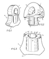
- - la figure 1 est une vue en perspective du marteau, les deux parties étant assemblées,
- - la figure 2 est une vue en perspective de la partie support,
- - la figure 3 est une vue en perspective de la partie active,
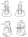
- - les figures 4, 5, 6 et 7 illustrent par différente vue en perspective la mise en place des deux parties constitutives du marteau,
- - la figure 8 est une vue de face de la partie support,
- - la figure 9 est une vue de dessus correspondant à la figure 8,
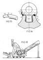
- - la figure 10 est une vue de profil correspondant à la figure 8,
- - la figure 11 est une vue de face et en coupe de la partie active de travail,
- - la figure 12 est une vue en plan correspondant à la figure 11,
- - la figure 13 est une vue en coupe transversale considérée selon les lignes 13-13 de la figure 11,
- - la figure 14 est une vue en coupe montrant l'assemblage des deux parties constitutives du marteau,
- - la figure 15 montre un exemple de réalisation d'un moyen de verrouillage entre les deux parties,
- - la figure 16 est une vue à caractère schématique montrant un exemple d'application du marteau dans une machine de broyage des carrosseries de véhicules automobiles.
- FIG. 1 is a perspective view of the hammer, the two parts being assembled,
- FIG. 2 is a perspective view of the support part,
- FIG. 3 is a perspective view of the active part,
- FIGS. 4, 5, 6 and 7 illustrate by different perspective view the positioning of the two constituent parts of the hammer,
- FIG. 8 is a front view of the support part,
- FIG. 9 is a top view corresponding to FIG. 8,
- FIG. 10 is a side view corresponding to FIG. 8,
- FIG. 11 is a front view in section of the active working part,
- FIG. 12 is a plan view corresponding to FIG. 11,
- FIG. 13 is a cross-sectional view taken along lines 13-13 of FIG. 11,
- FIG. 14 is a sectional view showing the assembly of the two constituent parts of the hammer,
- FIG. 15 shows an exemplary embodiment of a locking means between the two parts,
- - Figure 16 is a schematic view showing an example of application of the hammer in a grinding machine for motor vehicle bodies.
Afin de rendre plus concret l'objet de l'invention, on le décrit maintenant d'une manière non limitative en se référant aux exemples de réalisation des figures des dessins.In order to make the object of the invention more concrete, it is now described in a nonlimiting manner with reference to the exemplary embodiments of the figures of the drawings.
Selon l'invention, le marteau désigné dans son ensemble par (M) est exécuté en deux parties mécaniquement distinctes (1) et (2). La partie (1) est destinée à être accouplée par exemple sur une partie appropriée d'une machine à broyer, tandis que la partie (2) constitue la partie active de travail.According to the invention, the hammer designated as a whole by (M) is executed in two mechanically distinct parts (1) and (2). The part (1) is intended to be coupled for example to an appropriate part of a grinding machine, while the part (2) constitutes the active working part.
Compte-tenu du caractère indépendant des deux parties (1) et (2), il est donc aisé de les exécuter selon des degrés de dureté différent. Par exemple, la partie de fixation (1) à une dureté de l'ordre de 200 brinells alors que la partie active du travail (2) à une dureté de l'ordre de 500 brinells ou plus. Un traitement thermique particulier relevant d'un savoir-faire comme indiqué en préambule ne s'impose plus.Given the independent nature of the two parts (1) and (2), it is therefore easy to execute them according to different degrees of hardness. For example, the fixing part (1) has a hardness of around 200 strands while the active part of the work (2) has a hardness of around 500 strands or more. A specific heat treatment based on know-how as indicated in the preamble is no longer necessary.
On souligne que la base de la partie active de travail en combinaison avec les côtés latéraux, présente un profil (2a) de tout type connu et approprié tel que celui fréquemment utilisé pour de tels marteaux. La partie support (1) présente une ouvertrue centrale (1a) pour son montage notamment sur un arbre.It is emphasized that the base of the active working part in combination with the lateral sides, has a profile (2a) of any known and suitable type such as that frequently used for such hammers. The support part (1) has a central opening (1a) for its mounting in particular on a shaft.
D'une manière importante, chaque partie (1) et (2) est agencée en combinaison avec des moyens complémentaires de verrouillage permettant d'assurer à volonté leur accouplement relatif. Dans ce but, la partie support présente, en débordement de son plan de joint (1c), une tête axiale cylindrique profilée (1b) susceptible de coopérer avec un logement complémentaire (2b) formé axialement dans l'épaisseur de la partie active de travail (2), à partir de son plan de joint (2c).Importantly, each part (1) and (2) is arranged in combination with complementary locking means making it possible to ensure their relative coupling at will. For this purpose, the support part has, in overflow from its joint plane (1c), a profiled cylindrical axial head (1b) capable of cooperating with a complementary housing (2b) formed axially in the thickness of the active working part. (2), from its joint plane (2c).
D'une manière préférée, la tête d'accouplement (1b) et son logement complémentaire (2b) présentent des agencements en relief et en creux convenablement profilés pour assurer entre les deux parties (1) et (2) un assemblage mécanique. La tête d'accouplement (1b) présente verticalement sur sa hauteur, deux empreintes en relief (1d) et (1e) diamètralement opposées et formant chacune deux portées tronconiques de section progressive en direction de son extrémité libre. Entre les empreintes tronconiques en relief (1d) et (1e) la tête d'accouplement (1b) laisse donc subsister deux logements semi-cylindriques (1b1) diamètralement opposées.Preferably, the coupling head (1b) and its complementary housing (2b) have relief and hollow arrangements suitably profiled to ensure between the two parts (1) and (2) a mechanical assembly. The coupling head (1b) has vertically over its height, two raised impressions (1d) and (1e) diametrically opposite and each forming two frustoconical bearing surfaces of progressive section in the direction of its free end. Between the frustoconical imprints in relief (1d) and (1e) the coupling head (1b) therefore leaves two diametrically opposite semi-cylindrical housings (1b1).
De façon complémentaire, le logement axial (2b) de la partie active (2) présente, verticalement sur sa hauteur, deux empreintes en creux semi-cylindrique (2d) et (2e) diamètralement opposées et déterminées pour permettre l'engagement des empreintes en relief (1d) et (1e) de la tête (1b). Entre les empreintes en creux semi-cylindriques (2d) et (2e), le logement (2b) laisse subsister deux portées (2b1) diamétralement opposées, lesdites portées présentant une conicité correspondante à celle des empreintes en relief (1d) et (1e). Les empreintes (1d-2d) et (1e-2e) sont décalées angulairement de 90 degrés.In a complementary manner, the axial housing (2b) of the active part (2) has, vertically over its height, two semi-cylindrical hollow imprints (2d) and (2e) diametrically opposite and determined to allow the engagement of the imprints in relief (1d) and (1e) of the head (1b). Between the semi-cylindrical hollow imprints (2d) and (2e), the housing (2b) leaves two diametrically opposed bearing surfaces (2b1), said bearing surfaces having a conicity corresponding to that of the relief imprints (1d) and (1e) . The footprints (1d-2d) and (1e-2e) are offset angularly by 90 degrees.
Suivant une autre caractéristique, les plans de joint (1c)-(2c) de chacune des parties (1) et (2) présentent en combinaison des agencements conformés pour autoriser l'indexation en position d'accouplement desdites parties et l'engagement d'organes de verrouillage. Le plan de joint (1c) de la partie (1) présente deux ergots (1f) et (1g) diagonalement opposés et situés en débordement des extrémités correspondantes dudit plan (1c). Ces ergots font office de butées angulaires pour le positionnement et l'indexation de la partie active de travail (2) comme indiqué dans la suite de la description.According to another characteristic, the joint planes (1c) - (2c) of each of the parts (1) and (2) have in combination arrangements designed to allow indexing in the coupling position of said parts and the engagement of 'locking devices. The joint plane (1c) of the part (1) has two lugs (1f) and (1g) diagonally opposite and located beyond the corresponding ends of said plane (1c). These lugs act as angular stops for positioning and indexing the active working part (2) as indicated in the following description.
A proximité de chacun des ergots d'arrêt (1f) et (1g) et concentriquement à la tête (1b), le plan de joints (1c) présente un profil semi-circuliare (1h-1i) qui fait office de rampe coopérant en appui avec une partie correspondante du plan de joint (2c) de la partie active de travail (2).Close to each of the stop lugs (1f) and (1g) and concentrically with the head (1b), the joint plane (1c) has a semi-circular profile (1h-1i) which acts as a ramp cooperating in support with a corresponding part of the joint plane (2c) of the active working part (2).
Du côté opposé aux ergots d'arrêt (1f) et (1g), le plan du joint (1c) présente symétriquement deux rainures profilées en arc de cercle (1j) et (1k). D'une manière correspondante, le plan de joint (2c) de la partie active de travail (2), présente symétriquement deux rainures profilées en arc de cercle (2f) et (2g) de sorte qu'en position d'accouplement des deux parties (1) et (2), lesdites rainures (2f)-(2g) et (1j)-(1k) forment un tunnel de guidage pour l'engagement d'un organe de verrouillage en position angulaire desdites deux parties (1) et (2).On the side opposite to the locking pins (1f) and (1g), the plane of the joint (1c) has symmetrically two grooves profiled in an arc (1j) and (1k). Correspondingly, the joint plane (2c) of the active working part (2), symmetrically has two grooves profiled in an arc (2f) and (2g) so that in the coupling position of the two parts (1) and (2), said grooves (2f) - (2g) and (1j) - (1k) form a guide tunnel for the engagement of a locking member in angular position of said two parts (1) and (2).
A noter que la section transversale des rainures (1j) et (1k) est méplate, tandis que la section transversale des rainures (2f) et (2g) est semi-circulaire (figure 8 et 11).Note that the cross section of the grooves (1j) and (1k) is flat, while the cross section of the grooves (2f) and (2g) is semi-circular (Figure 8 and 11).
Comme illustré à la figure 15, chaque organe de verrouillage est constitué par une clavette (3) profilée en arc de cercle d'une manière complémentaire aux rainures (2f-2g) et (1j-1k). La section transversale de chacune des clavettes est semi-circulaire pour correspondre au tunnel de guidage, résultant de la juxtaposition des rainures profilées (2f-2g) et (1j-1k).As illustrated in FIG. 15, each locking member is constituted by a key (3) profiled in an arc of a circle in a manner complementary to the grooves (2f-2g) and (1j-1k). The cross section of each of the keys is semi-circular to correspond to the guide tunnel, resulting from the juxtaposition of the profiled grooves (2f-2g) and (1j-1k).
A l'une des extrémités, la clavette (3) est prolongée par une partie méplate (3a), une ligne transversale de prépliage (3b) permettant de rabattre angulairement cette partie (3a) dans une empreinte complémentaire (1m)-(1n) établie dans l'épaisseur de chacune des faces transversales du corps supérieur (1), en continuité et en correspondance avec chacune des rainures (1j) et (1k).At one end, the key (3) is extended by a flat part (3a), a transverse pre-folding line (3b) making it possible to angularly fold this part (3a) into a complementary imprint (1m) - (1n) established in the thickness of each of the transverse faces of the upper body (1), in continuity and in correspondence with each of the grooves (1d) and (1k).
A ce stade de la description, il convient d'analyser comment on opère l'accouplement et le verrouillage en position angulaire des deux parties (1) et (2) en se référant plus particulièrement aux figures 4, 5, 6 et 7. On suppose la partie support (1) montée sur l'arbre de rotor par exemple, qui n'est pas représenté dans ces vues pour une meilleure clarté.At this stage of the description, it is necessary to analyze how the coupling and the locking in angular position of the two parts (1) and (2) are operated, with particular reference to FIGS. 4, 5, 6 and 7. On assumes the support part (1) mounted on the rotor shaft for example, which is not shown in these views for better clarity.
La partie active du travail (2) est disposée en regard de la partie support (1), d'une manière perpendiculaire à cette dernière pour que les empreintes en creux (2d) et (2e) de la partie (2) se trouvent en correspondance et en alignement avec les empreintes (1d) et (1e) de la partie support (1) figure (4). On engage alors le logement axial (2b) de la partie active (2) sur la tête conique de centrage et d'accouplement (1b) de sorte que les empreintes semi-cylindriques (2d) et (2e) sont engagées et postionnées sur les empreintes en relief tronconiques (1d) et (1e). La partie active est toujours orientée d'une manière perpendiculaire à la partie support (1) (figure 5).The active part of the work (2) is arranged opposite the support part (1), perpendicularly to the latter so that the indentations (2d) and (2e) of the part (2) are in correspondence and alignment with the imprints (1d) and (1e) of the support part (1) figure (4). The axial housing (2b) of the active part (2) is then engaged on the conical centering and coupling head (1b) so that the semi-cylindrical impressions (2d) and (2e) are engaged and positioned on the tapered relief imprints (1d) and (1e). The active part is always oriented perpendicular to the support part (1) (Figure 5).
Les deux plans de joints (1c) et (2c) étant en contact, il suffit de faire pivoter circulairement de 90 degrés la partie (2) autour de la tête d'accouplement (1b).The two joint planes (1c) and (2c) being in contact, it suffices to rotate the part (2) circularly by 90 degrees around the coupling head (1b).
Les portées tronconiques (1d) et (1e) échappent de ce fait les logements cylindriques (2d) et (2e). Pendant la rotation, les portées tronconiques (1d) et (1e) ne sont pas en contact avec les portées tronconiques subséquentes (2b1), ce qui rend la rotation facile.The frustoconical surfaces (1d) and (1e) therefore escape the cylindrical housings (2d) and (2e). During rotation, the frusto-conical surfaces (1d) and (1e) are not in contact with the subsequent frusto-conical surfaces (2b1), which makes rotation easy.
En fin de rotation de la partie (2), le profil semi-circulaire formant rampe (1h) et (1i) de la partie (1) écarte très légèrement la partie active (2) rattrapant ainsi avantageusement le jeu fonctionnel.At the end of rotation of the part (2), the semi-circular profile forming a ramp (1h) and (1i) of the part (1) very slightly spreads the active part (2) thus advantageously catching up with the functional play.
Les ergots (1f) et (1g) assurent l'indexation angulaire des deux parties.The lugs (1f) and (1g) ensure the angular indexing of the two parts.
Dans cette position d'indexation et de verrouillage, il suffit d'engager comme indiqué, les clavettes (3) pour obtenir la mise en contact parfaite des parties tronconiques (1d - 1e) et (2b1) par rattrapage complet du jeu fonctionnel ainsi que le blocage angulaire des deux parties (1) et (2) dans le sens opposé aux ergots (1f - 1g). Chaque clavette est engagée dans le tunnel profilé en arc de cercle résultant des empreintes (1j-2f) et (1h-2g), tandis que la partie méplate (3a) des clavettes est rabaissée et plaquée dans l'empreinte correspondante (1m) et (1n). A noter que chacune des empreintes (1m) et (1n) présente en partie basse, une déformation en creux (1m1) et (1n1) pour autoriser le passage d'un outil quelconque pour relever la partie (3a) de la clavette en vue de retirer cette dernière pour le déverrouillage des deux parties constitutives du marteau.In this indexing and locking position, it suffices to engage, as indicated, the keys (3) for obtain perfect contacting of the frustoconical parts (1d - 1e) and (2b1) by completely taking up the functional clearance as well as the angular blocking of the two parts (1) and (2) in the opposite direction to the pins (1f - 1g) . Each key is engaged in the tunnel shaped in a circular arc resulting from the imprints (1d-2f) and (1h-2g), while the flat part (3a) of the keys is lowered and pressed into the corresponding imprint (1m) and (1n). Note that each of the indentations (1m) and (1n) has in the lower part, a hollow deformation (1m1) and (1n1) to allow the passage of any tool to raise the part (3a) of the key in view to remove the latter to unlock the two constituent parts of the hammer.
On conçoit donc, compte-tenu des caractéristiques de construction et de conception du marteau, qu'il est nécessaire après usure, de changer uniquement la partie active.It is therefore conceivable, taking into account the construction and design characteristics of the hammer, that it is necessary after wear, to change only the active part.
Outre l'économie en résultant, il n'est plus nécessaire d'intervenir sur la machine recevant ces marteaux, notamment au niveau de leur accouplement sur ladite machine. Enfin, comme indiqué précédemment, l'ensemble du marteau peut de ce fait être soumis à deux traitements thermiques distincts pour obtenir des degrés de dureté différents eu égard aux efforts respectifs auxquels sont soumises les parties constitutives dudit marteau.In addition to the resulting economy, it is no longer necessary to intervene on the machine receiving these hammers, in particular at the level of their coupling on said machine. Finally, as indicated above, the whole hammer can therefore be subjected to two separate heat treatments to obtain different degrees of hardness having regard to the respective forces to which the constituent parts of said hammer are subjected.
L'invention trouve une application particulièrement avantageuse pour équiper les machines à broyer les carrosseries de véhicules automobiles comme illustré figure 16.The invention finds a particularly advantageous application for equipping machines for grinding the bodies of motor vehicles as illustrated in FIG. 16.
Il est souligné que le mode d'assemblage et d'accouplement décrit pour un marteau de broyage, peut s'appliquer, sans pour cela sortir du cadre de l'invention, à d'autres types d'outils.It is emphasized that the method of assembly and coupling described for a grinding hammer can be applied, without departing from the scope of the invention, to other types of tools.
L'invention ne se limite aucunement à celui de ses modes d'application non plus qu'à ceux des modes de réalisation de ses diverses parties ayant plus spécialement été indiquées ; elle en embrasse au contraire toutes les variantes.The invention is in no way limited to that of its modes of application any more than to those of embodiments of its various parts having been more specially indicated; on the contrary, it embraces all its variants.
Claims (7)
Applications Claiming Priority (2)
| Application Number | Priority Date | Filing Date | Title |
|---|---|---|---|
| FR8604205A FR2595960B1 (en) | 1986-03-18 | 1986-03-18 | HAMMER IN PARTICULAR FOR MACHINES FOR GRINDING SCRAP OR OTHER METALS |
| FR8604205 | 1986-03-18 |
Publications (2)
| Publication Number | Publication Date |
|---|---|
| EP0240440A2 true EP0240440A2 (en) | 1987-10-07 |
| EP0240440A3 EP0240440A3 (en) | 1989-03-15 |
Family
ID=9333477
Family Applications (1)
| Application Number | Title | Priority Date | Filing Date |
|---|---|---|---|
| EP87420075A Withdrawn EP0240440A3 (en) | 1986-03-18 | 1987-03-18 | Hammer, especially for machines for grinding scrap or other metals |
Country Status (2)
| Country | Link |
|---|---|
| EP (1) | EP0240440A3 (en) |
| FR (1) | FR2595960B1 (en) |
Cited By (5)
| Publication number | Priority date | Publication date | Assignee | Title |
|---|---|---|---|---|
| CN101703952B (en) * | 2009-01-11 | 2011-04-27 | 李正峰 | Hammer of hammer crusher |
| CN102327795A (en) * | 2011-08-05 | 2012-01-25 | 昆明理工大学 | Chromium (Cr)-free high-boron iron-based wear-resistant duplex metal composite hammerhead and preparation method thereof |
| US8308094B2 (en) | 2009-02-26 | 2012-11-13 | Esco Corp. | Shredder hammers including improved engagement between the hammer pin and the hammer |
| EP2377619A3 (en) * | 2010-04-16 | 2013-08-28 | Betek GmbH & Co. KG | Cutting body |
| US10525477B2 (en) | 2014-04-30 | 2020-01-07 | Esco Group Llc | Hammer for material reducing machines |
Citations (1)
| Publication number | Priority date | Publication date | Assignee | Title |
|---|---|---|---|---|
| DE1142267B (en) * | 1960-05-03 | 1963-01-10 | Eickhoff Geb | Striking tool for beater mills |
Family Cites Families (1)
| Publication number | Priority date | Publication date | Assignee | Title |
|---|---|---|---|---|
| FR2257343A1 (en) * | 1974-01-16 | 1975-08-08 | Matelest Sa | Two-part refuse comminuter arm - impact block fits into recess in impact face, secured by bolts |
-
1986
- 1986-03-18 FR FR8604205A patent/FR2595960B1/en not_active Expired
-
1987
- 1987-03-18 EP EP87420075A patent/EP0240440A3/en not_active Withdrawn
Patent Citations (1)
| Publication number | Priority date | Publication date | Assignee | Title |
|---|---|---|---|---|
| DE1142267B (en) * | 1960-05-03 | 1963-01-10 | Eickhoff Geb | Striking tool for beater mills |
Cited By (6)
| Publication number | Priority date | Publication date | Assignee | Title |
|---|---|---|---|---|
| CN101703952B (en) * | 2009-01-11 | 2011-04-27 | 李正峰 | Hammer of hammer crusher |
| US8308094B2 (en) | 2009-02-26 | 2012-11-13 | Esco Corp. | Shredder hammers including improved engagement between the hammer pin and the hammer |
| EP2377619A3 (en) * | 2010-04-16 | 2013-08-28 | Betek GmbH & Co. KG | Cutting body |
| CN102327795A (en) * | 2011-08-05 | 2012-01-25 | 昆明理工大学 | Chromium (Cr)-free high-boron iron-based wear-resistant duplex metal composite hammerhead and preparation method thereof |
| US10525477B2 (en) | 2014-04-30 | 2020-01-07 | Esco Group Llc | Hammer for material reducing machines |
| US11951484B2 (en) | 2014-04-30 | 2024-04-09 | Esco Group Llc | Hammer for material reducing machines |
Also Published As
| Publication number | Publication date |
|---|---|
| FR2595960B1 (en) | 1989-11-10 |
| EP0240440A3 (en) | 1989-03-15 |
| FR2595960A1 (en) | 1987-09-25 |
Similar Documents
| Publication | Publication Date | Title |
|---|---|---|
| EP1846665B1 (en) | Conical roller bearing comprising a filter cage | |
| LU86192A1 (en) | MOLD FOR PNEUMATIC TIRES | |
| FR2640010A1 (en) | ARRANGEMENT FOR FIXING A HIGH-HARDNESS BEARING RING INTO THE LOWEST HARDNESS OF A HOUSING OF A HOUSING OR ON THE LOWEST HARDNESS SURFACE OF A SHAFT OR THE LIKE | |
| EP0240440A2 (en) | Hammer, especially for machines for grinding scrap or other metals | |
| EP0359885B1 (en) | Key with a sliding element, safety cylinder, and lock provided with such a cylinder | |
| EP0664184B1 (en) | Ball-joint bearing with high mechanical strength and method for manufacturing it | |
| FR2752022A1 (en) | CONNECTING ROD FOR INTERNAL COMBUSTION ENGINES | |
| EP0263769A1 (en) | Door or window hinge with an axially fixed pin | |
| EP1702693B1 (en) | Tool chuck for a rotating machine | |
| FR2538754A1 (en) | Transfer press with tool change mechanism | |
| EP3412523A1 (en) | Linkage subassembly and linkage held in a transport position by means of a locking element, and method for locking said linkage by means of such a locking element | |
| FR2577969A1 (en) | Piston-type cylinder lock for a key with indentations | |
| FR2523010A1 (en) | Method of milling external or internal surfaces of cylindrical work - uses free wheel with helical teeth moved axially through or over work | |
| FR2703289A3 (en) | Electric perforator. | |
| FR2994887A1 (en) | DEVICE AND METHOD FOR PRODUCING PREFORMS | |
| FR2738518A1 (en) | Interchangeable grinding head for grinding spot welding electrodes | |
| FR3066973B1 (en) | LOCKING KEY FOR A WHEELHOUSE, WAREHOUSE SUB-ASSEMBLY AND WHEELHOUSE HAVING SUCH A LOCK KEY AND METHOD OF SETTING SUCH A LOCKING KEY ON A WHEELHOUSE | |
| EP2086722B1 (en) | Tool for roller burnishing a toroidal fillet | |
| FR2468463A1 (en) | DEVICE FOR LOCKING PLATE PLATES ON PRINTING MACHINE | |
| CA2308860C (en) | Drain inlet with articulated and locked cover and grating | |
| FR2785341A1 (en) | Releasable shaft lock for drive transmission has recessed key fitting in hole in component to be mounted on shaft to releasable lock them together | |
| EP0034977B1 (en) | Industrial process for making jewellery, especially rings, rather of precious metal, provided with set stones, device for performing said process of obtaining jewellery | |
| FR2803230A1 (en) | Sheet steel press e.g. for vehicle body components has recessed matrix forming relaxation cavity | |
| EP2268879B1 (en) | Method for making a pivoting ratchet for the lock of an automobile door leaf | |
| EP0038749A1 (en) | Chuck, e.g. for machine tools |
Legal Events
| Date | Code | Title | Description |
|---|---|---|---|
| PUAI | Public reference made under article 153(3) epc to a published international application that has entered the european phase |
Free format text: ORIGINAL CODE: 0009012 |
|
| AK | Designated contracting states |
Kind code of ref document: A2 Designated state(s): AT BE CH DE ES GB GR IT LI LU NL SE |
|
| PUAL | Search report despatched |
Free format text: ORIGINAL CODE: 0009013 |
|
| AK | Designated contracting states |
Kind code of ref document: A3 Designated state(s): AT BE CH DE ES GB GR IT LI LU NL SE |
|
| STAA | Information on the status of an ep patent application or granted ep patent |
Free format text: STATUS: THE APPLICATION IS DEEMED TO BE WITHDRAWN |
|
| 18D | Application deemed to be withdrawn |
Effective date: 19890916 |
|
| RIN1 | Information on inventor provided before grant (corrected) |
Inventor name: PASQUALINI,CHARLES |