EP0240440A2 - Hammer für Maschinen zum Zerkleinern von Schrott oder anderen Metallen - Google Patents
Hammer für Maschinen zum Zerkleinern von Schrott oder anderen Metallen Download PDFInfo
- Publication number
- EP0240440A2 EP0240440A2 EP87420075A EP87420075A EP0240440A2 EP 0240440 A2 EP0240440 A2 EP 0240440A2 EP 87420075 A EP87420075 A EP 87420075A EP 87420075 A EP87420075 A EP 87420075A EP 0240440 A2 EP0240440 A2 EP 0240440A2
- Authority
- EP
- European Patent Office
- Prior art keywords
- grooves
- joint plane
- hammer
- parts
- locking
- Prior art date
- Legal status (The legal status is an assumption and is not a legal conclusion. Google has not performed a legal analysis and makes no representation as to the accuracy of the status listed.)
- Withdrawn
Links
Images

Classifications
-
- B—PERFORMING OPERATIONS; TRANSPORTING
- B02—CRUSHING, PULVERISING, OR DISINTEGRATING; PREPARATORY TREATMENT OF GRAIN FOR MILLING
- B02C—CRUSHING, PULVERISING, OR DISINTEGRATING IN GENERAL; MILLING GRAIN
- B02C13/00—Disintegrating by mills having rotary beater elements ; Hammer mills
- B02C13/26—Details
- B02C13/28—Shape or construction of beater elements
Definitions
- the invention relates to a hammer in particular for machines for grinding scrap metal or other metals.
- the object of the invention relates to the technical sector of mechanical metalworking without substantial removal of material.
- the hammers have, in a monobloc manner with their coupling part, an active working part suitably profiled taking into account the operations to be carried out and in an attempt to reduce as much as possible the wear phenomenon which appears as the job.
- this active part which must shred very resistant products, must reach a very high hardness greater than 500 strands.
- the part for fixing these hammers to the shaft can be satisfied with a hardness of the order of 200 strands since this part is obviously not stressed in the same way.
- the whole hammer must therefore undergo a special heat treatment in order to progressively go from a low hardness to a very high hardness. This results in very important know-how. In most cases, the optimum value for the hardness of the active part cannot be reached.
- the invention set itself the aim of remedying these drawbacks by creating a hammer which is executed in two mechanically distinct parts, one part intended to be fixed on a support member of the machine and another active part of determined profile and intended to ensure striking, said parts being arranged in combination with complementary means of assembly and locking in position making it possible to ensure, at will, their relative assembly and disassembly.
- the fixing part is executed in high tenacity steel, while the active working part is executed in very high hardness steel.
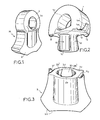
- the hammer designated as a whole by (M) is executed in two mechanically distinct parts (1) and (2).
- the part (1) is intended to be coupled for example to an appropriate part of a grinding machine, while the part (2) constitutes the active working part.
- the fixing part (1) has a hardness of around 200 strands while the active part of the work (2) has a hardness of around 500 strands or more.
- a specific heat treatment based on know-how as indicated in the preamble is no longer necessary.
- the base of the active working part in combination with the lateral sides has a profile (2a) of any known and suitable type such as that frequently used for such hammers.
- the support part (1) has a central opening (1a) for its mounting in particular on a shaft.
- each part (1) and (2) is arranged in combination with complementary locking means making it possible to ensure their relative coupling at will.
- the support part has, in overflow from its joint plane (1c), a profiled cylindrical axial head (1b) capable of cooperating with a complementary housing (2b) formed axially in the thickness of the active working part. (2), from its joint plane (2c).
- the coupling head (1b) and its complementary housing (2b) have relief and hollow arrangements suitably profiled to ensure between the two parts (1) and (2) a mechanical assembly.
- the coupling head (1b) has vertically over its height, two raised impressions (1d) and (1e) diametrically opposite and each forming two frustoconical bearing surfaces of progressive section in the direction of its free end. Between the frustoconical imprints in relief (1d) and (1e) the coupling head (1b) therefore leaves two diametrically opposite semi-cylindrical housings (1b1).
- the axial housing (2b) of the active part (2) has, vertically over its height, two semi-cylindrical hollow imprints (2d) and (2e) diametrically opposite and determined to allow the engagement of the imprints in relief (1d) and (1e) of the head (1b).
- the housing (2b) leaves two diametrically opposed bearing surfaces (2b1), said bearing surfaces having a conicity corresponding to that of the relief imprints (1d) and (1e) .
- the footprints (1d-2d) and (1e-2e) are offset angularly by 90 degrees.
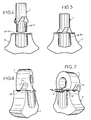
- the joint planes (1c) - (2c) of each of the parts (1) and (2) have in combination arrangements designed to allow indexing in the coupling position of said parts and the engagement of 'locking devices.
- the joint plane (1c) of the part (1) has two lugs (1f) and (1g) diagonally opposite and located beyond the corresponding ends of said plane (1c). These lugs act as angular stops for positioning and indexing the active working part (2) as indicated in the following description.
- the joint plane (1c) has a semi-circular profile (1h-1i) which acts as a ramp cooperating in support with a corresponding part of the joint plane (2c) of the active working part (2).
- the plane of the joint (1c) has symmetrically two grooves profiled in an arc (1j) and (1k).
- the joint plane (2c) of the active working part (2) symmetrically has two grooves profiled in an arc (2f) and (2g) so that in the coupling position of the two parts (1) and (2), said grooves (2f) - (2g) and (1j) - (1k) form a guide tunnel for the engagement of a locking member in angular position of said two parts (1) and (2).
- each locking member is constituted by a key (3) profiled in an arc of a circle in a manner complementary to the grooves (2f-2g) and (1j-1k).
- the cross section of each of the keys is semi-circular to correspond to the guide tunnel, resulting from the juxtaposition of the profiled grooves (2f-2g) and (1j-1k).
- the key (3) is extended by a flat part (3a), a transverse pre-folding line (3b) making it possible to angularly fold this part (3a) into a complementary imprint (1m) - (1n) established in the thickness of each of the transverse faces of the upper body (1), in continuity and in correspondence with each of the grooves (1d) and (1k).
- the active part of the work (2) is arranged opposite the support part (1), perpendicularly to the latter so that the indentations (2d) and (2e) of the part (2) are in correspondence and alignment with the imprints (1d) and (1e) of the support part (1) figure (4).
- the axial housing (2b) of the active part (2) is then engaged on the conical centering and coupling head (1b) so that the semi-cylindrical impressions (2d) and (2e) are engaged and positioned on the tapered relief imprints (1d) and (1e).
- the active part is always oriented perpendicular to the support part (1) ( Figure 5).
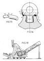
- the frustoconical surfaces (1d) and (1e) therefore escape the cylindrical housings (2d) and (2e). During rotation, the frusto-conical surfaces (1d) and (1e) are not in contact with the subsequent frusto-conical surfaces (2b1), which makes rotation easy.
- the semi-circular profile forming a ramp (1h) and (1i) of the part (1) very slightly spreads the active part (2) thus advantageously catching up with the functional play.
- the lugs (1f) and (1g) ensure the angular indexing of the two parts.
- each of the indentations (1m) and (1n) has in the lower part, a hollow deformation (1m1) and (1n1) to allow the passage of any tool to raise the part (3a) of the key in view to remove the latter to unlock the two constituent parts of the hammer.
- the invention finds a particularly advantageous application for equipping machines for grinding the bodies of motor vehicles as illustrated in FIG. 16.
- the invention is in no way limited to that of its modes of application any more than to those of embodiments of its various parts having been more specially indicated; on the contrary, it embraces all its variants.
Landscapes
- Engineering & Computer Science (AREA)
- Food Science & Technology (AREA)
- Percussive Tools And Related Accessories (AREA)
- Crushing And Pulverization Processes (AREA)
Applications Claiming Priority (2)
| Application Number | Priority Date | Filing Date | Title |
|---|---|---|---|
| FR8604205 | 1986-03-18 | ||
| FR8604205A FR2595960B1 (fr) | 1986-03-18 | 1986-03-18 | Marteau notamment pour machines a broyer la ferraille ou autres metaux |
Publications (2)
| Publication Number | Publication Date |
|---|---|
| EP0240440A2 true EP0240440A2 (de) | 1987-10-07 |
| EP0240440A3 EP0240440A3 (de) | 1989-03-15 |
Family
ID=9333477
Family Applications (1)
| Application Number | Title | Priority Date | Filing Date |
|---|---|---|---|
| EP87420075A Withdrawn EP0240440A3 (de) | 1986-03-18 | 1987-03-18 | Hammer für Maschinen zum Zerkleinern von Schrott oder anderen Metallen |
Country Status (2)
| Country | Link |
|---|---|
| EP (1) | EP0240440A3 (de) |
| FR (1) | FR2595960B1 (de) |
Cited By (5)
| Publication number | Priority date | Publication date | Assignee | Title |
|---|---|---|---|---|
| CN101703952B (zh) * | 2009-01-11 | 2011-04-27 | 李正峰 | 锤式破碎机锤头 |
| CN102327795A (zh) * | 2011-08-05 | 2012-01-25 | 昆明理工大学 | 一种无Cr高硼铁基耐磨双金属复合锤头及其制备方法 |
| US8308094B2 (en) | 2009-02-26 | 2012-11-13 | Esco Corp. | Shredder hammers including improved engagement between the hammer pin and the hammer |
| EP2377619A3 (de) * | 2010-04-16 | 2013-08-28 | Betek GmbH & Co. KG | Schneidkörper |
| US10525477B2 (en) | 2014-04-30 | 2020-01-07 | Esco Group Llc | Hammer for material reducing machines |
Families Citing this family (1)
| Publication number | Priority date | Publication date | Assignee | Title |
|---|---|---|---|---|
| RU2246354C1 (ru) * | 2003-12-15 | 2005-02-20 | Северо-Кавказский горно-металлургический институт (государственный технологический университет) (СКГМИ (ГТУ) | Центробежная дробильно-измельчительная установка |
Family Cites Families (2)
| Publication number | Priority date | Publication date | Assignee | Title |
|---|---|---|---|---|
| DE1142267B (de) * | 1960-05-03 | 1963-01-10 | Eickhoff Geb | Schlagwerkzeug fuer Schlaegermuehlen |
| FR2257343A1 (en) * | 1974-01-16 | 1975-08-08 | Matelest Sa | Two-part refuse comminuter arm - impact block fits into recess in impact face, secured by bolts |
-
1986
- 1986-03-18 FR FR8604205A patent/FR2595960B1/fr not_active Expired
-
1987
- 1987-03-18 EP EP87420075A patent/EP0240440A3/de not_active Withdrawn
Cited By (6)
| Publication number | Priority date | Publication date | Assignee | Title |
|---|---|---|---|---|
| CN101703952B (zh) * | 2009-01-11 | 2011-04-27 | 李正峰 | 锤式破碎机锤头 |
| US8308094B2 (en) | 2009-02-26 | 2012-11-13 | Esco Corp. | Shredder hammers including improved engagement between the hammer pin and the hammer |
| EP2377619A3 (de) * | 2010-04-16 | 2013-08-28 | Betek GmbH & Co. KG | Schneidkörper |
| CN102327795A (zh) * | 2011-08-05 | 2012-01-25 | 昆明理工大学 | 一种无Cr高硼铁基耐磨双金属复合锤头及其制备方法 |
| US10525477B2 (en) | 2014-04-30 | 2020-01-07 | Esco Group Llc | Hammer for material reducing machines |
| US11951484B2 (en) | 2014-04-30 | 2024-04-09 | Esco Group Llc | Hammer for material reducing machines |
Also Published As
| Publication number | Publication date |
|---|---|
| FR2595960A1 (fr) | 1987-09-25 |
| EP0240440A3 (de) | 1989-03-15 |
| FR2595960B1 (fr) | 1989-11-10 |
Similar Documents
| Publication | Publication Date | Title |
|---|---|---|
| LU86192A1 (fr) | Moule pour bandages pneumatiques | |
| EP1846665B1 (de) | Konisches kugellager mit filterkäfig | |
| FR2640010A1 (fr) | Agencement pour la fixation d'une bague de roulement de grande durete dans la surface d'alesage de plus faible durete d'un logement ou sur la surface laterale de plus faible durete d'un arbre ou d'un organe analogue | |
| CA2606243A1 (fr) | Procede et dispositif de liaison entre une piece d'usure et son support mis en jeu sur les equipements de manutention de materiaux par les engins de travaux publics | |
| EP0240440A2 (de) | Hammer für Maschinen zum Zerkleinern von Schrott oder anderen Metallen | |
| WO2000005035A1 (fr) | Dispositif de centrage et de bridage d'un ensemble de tolerie oud'une piece mecanique | |
| FR2752022A1 (fr) | Bielle de moteur a combustion interne | |
| EP0359885B1 (de) | Schlüssel mit Schiebeelement, Sicherheitszylinder, und Schloss mit solchen Zylindern | |
| EP0664184B1 (de) | Kugelgelenklager mit hoher mechanischer Festigkeit und sein Herstellungsverfahren | |
| EP0263769A1 (de) | Tür- oder Fensterscharnier mit axialer Blockierung des Bolzens | |
| FR3097144A1 (fr) | Outil de sertissage par frottement | |
| FR2538754A1 (fr) | Dispositif pour l'assemblage detachable d'elements de rails preneurs dans une presse-transfert | |
| FR2738518A1 (fr) | Tete de rodage amovible pour le rodage d'electrodes d'appareils de soudage | |
| FR2577969A1 (fr) | Serrure a cylindre a pistons pour clef a empreintes en creux | |
| FR2703289A3 (fr) | Perforateur électrique. | |
| FR3132036A1 (fr) | Outillage de poinçonnage de tôle et procédé de réglage de celui-ci | |
| FR2994887A1 (fr) | Dispositif et procede pour la realisation de preformes | |
| FR2468463A1 (fr) | Dispositif pour le verrouillage de plaques de cliches sur machine a imprimer | |
| CA2308860C (fr) | Bouche d'egout a couvercle et grille articules et verrouilles | |
| FR3066973B1 (fr) | Cle de blocage d'une timonerie, sous-ensemble de timonerie et timonerie presentant une telle cle de blocage et procede de mise en place d'une telle cle de blocage sur une timonerie | |
| EP0034977B1 (de) | Industrielles Verfahren zur Herstellung von Schmuck, insbesondere von mit eingefassten Steinen versehenen Ringen, vorzugsweise aus Edelmetall, Vorrichtung zur Durchführung dieses Verfahrens und der erhaltene Schmuck | |
| FR2721243A1 (fr) | Procédé de fabrication d'une charnière pour portes de véhicules. | |
| FR2803230A1 (fr) | Dispositif et procede de formage d'une tole permettant de limiter le retour elastique de la tole apres formage et utilisation | |
| EP2268879B1 (de) | Verfahren zur herstellung einer schwenksperrklinke für das schloss eines kraftfahrzeugtürflügels | |
| EP0038269A1 (de) | Spannfutter für Werkzeugmaschinen |
Legal Events
| Date | Code | Title | Description |
|---|---|---|---|
| PUAI | Public reference made under article 153(3) epc to a published international application that has entered the european phase |
Free format text: ORIGINAL CODE: 0009012 |
|
| AK | Designated contracting states |
Kind code of ref document: A2 Designated state(s): AT BE CH DE ES GB GR IT LI LU NL SE |
|
| PUAL | Search report despatched |
Free format text: ORIGINAL CODE: 0009013 |
|
| AK | Designated contracting states |
Kind code of ref document: A3 Designated state(s): AT BE CH DE ES GB GR IT LI LU NL SE |
|
| STAA | Information on the status of an ep patent application or granted ep patent |
Free format text: STATUS: THE APPLICATION IS DEEMED TO BE WITHDRAWN |
|
| 18D | Application deemed to be withdrawn |
Effective date: 19890916 |
|
| RIN1 | Information on inventor provided before grant (corrected) |
Inventor name: PASQUALINI,CHARLES |