EP0240358A2 - Maschine zum Trennen von Strickwaren - Google Patents
Maschine zum Trennen von Strickwaren Download PDFInfo
- Publication number
- EP0240358A2 EP0240358A2 EP87302921A EP87302921A EP0240358A2 EP 0240358 A2 EP0240358 A2 EP 0240358A2 EP 87302921 A EP87302921 A EP 87302921A EP 87302921 A EP87302921 A EP 87302921A EP 0240358 A2 EP0240358 A2 EP 0240358A2
- Authority
- EP
- European Patent Office
- Prior art keywords
- fabric
- belt
- roller
- output
- portions
- Prior art date
- Legal status (The legal status is an assumption and is not a legal conclusion. Google has not performed a legal analysis and makes no representation as to the accuracy of the status listed.)
- Withdrawn
Links
Images


Classifications
-
- D—TEXTILES; PAPER
- D06—TREATMENT OF TEXTILES OR THE LIKE; LAUNDERING; FLEXIBLE MATERIALS NOT OTHERWISE PROVIDED FOR
- D06H—MARKING, INSPECTING, SEAMING OR SEVERING TEXTILE MATERIALS
- D06H7/00—Apparatus or processes for cutting, or otherwise severing, specially adapted for the cutting, or otherwise severing, of textile materials
- D06H7/22—Severing by heat or by chemical agents
- D06H7/221—Severing by heat or by chemical agents by heat
- D06H7/225—Severing by heat or by chemical agents by heat using meltable yarns or interwoven metal wires heated by an electric current
-
- D—TEXTILES; PAPER
- D04—BRAIDING; LACE-MAKING; KNITTING; TRIMMINGS; NON-WOVEN FABRICS
- D04B—KNITTING
- D04B19/00—Unravelling knitted fabrics
-
- D—TEXTILES; PAPER
- D06—TREATMENT OF TEXTILES OR THE LIKE; LAUNDERING; FLEXIBLE MATERIALS NOT OTHERWISE PROVIDED FOR
- D06F—LAUNDERING, DRYING, IRONING, PRESSING OR FOLDING TEXTILE ARTICLES
- D06F73/00—Apparatus for smoothing or removing creases from garments or other textile articles by formers, cores, stretchers, or internal frames, with the application of heat or steam
Definitions
- the invention relates to machines for the separation of knitted fabrics into discrete portions by the effective removal of threads linking the portions.
- the object of the invention is to provide a machine for separating portions of knitted fabric linked by such resistant link threads whilst avoiding damage to the fabric portions.
- apparatus for separating knitted fabric comprising fabric portions linked by link threads, said apparatus comprising means for conveying the said fabric from an input station towards an output station, infra-red radiation means positioned so as, when connected to a source of electric power, to irradiate the fabric intermediate the stations, and means for controlling the output of the radiation means.
- the apparatus may further comprise means for treating the fabric intermediate the stations with steam.
- the control means may control the output of the radiation means in accordance with one or both of the rate of conveyance of the fabric intermediate the stations and the nature of the fabric.
- the apparatus may also provide means for distancing the fabric portions from one another after the separation thereof.
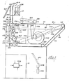
- the apparatus comprises essentially a free-standing cabinet 2, an infra-red heating unit 4 mounted transversely above the cabinet at the front end thereof by means of supports 6, and a control console 8.
- the upper part of the cabinet 2 projects rearwardly of the lower part, and the upper surface of the cabinet is defined by a portion of a continuous and permeable belt l0 extending between transverse roller l2 towards the front of the machine and a further transverse roller l4 towards the rear of the rearward extension l6 of the cabinet.
- the remainder of the path of the belt l0 is defined by transverse rollers 20, and 22.
- An electric motor 50 coupled to a tachogenerator l04 and to a speed reduction gear 52 having an output shaft 5l is located within the cabinet 2.
- the tachogenerator is replaced by an encoder or other device capable of producing an electrical output proportional to the motor speed.
- Drive belt ll0 is driven by a first pulley l20 on shaft 5l, and this in turn drives a pulley which is fast to one end of the rollers 20.
- a further belt ll2 similarly drives roller l4 at the same speed as roller 20 and in the same direction so that the upper reach of belt l0 travels in the direction of arrow l8.
- the belts driving the rollers l4 and 20, and those driving other rollers as will be described below, are generally accommodated in housings l5 to each side of the upper portion of cabinet 2.
- the other rollers supporting belt l0 are idlers.
- Transverse rollers 26 and 28 are mounted in bearings above the level of the upper reach of belt l0, intermediate rollers l2 and l4.
- a permeable conveyor belt 30 is arranged tautly about the roller 26,28, and roller 28 is driven from roller l4 via drive belt l08 which passes over pulleys fast to the rollers and two loose pulleys l24. This drive ensures that the lower reach of belt 30 moves in the same direction and at the same surface speed as belt l0.
- roller 26 The bearings of roller 26 are adjustably mounted so that the roller may be raised in an arcuate path of which the centre is the axis of roller 28. Moreover, the bearings of both rollers are so adjustable (and the belt l08 is sufficiently extensible) that the unit comprising roller 26 and 28 and the belt 30 can be moved a short distance bodily towards roller l2 or roller l4 if required.
- nip rollers 32, 34 are mounted forwardly of the cabinet, parallel to roller l2 and with their nip at about the level of the upper reach of belt l0.
- the bearings of upper roller 34 which is freely rotatable, are carried at the end of arms 36 which can be raised or lowered to provide an open or a tight nip between the rollers as required.
- Roller 32 is rotated by a V-belt ll4 driven by a spring-loaded variable-pitch V-belt pulley l22 on the shaft 5l of speed-reduction gear 52, the pulley ensuring that the roller 32 rotates at a surface speed proportional to but less than that of belt l0.
- a compensating pulley ll6 By adjusting the position of a compensating pulley ll6 between positions shown in full and in dotted lines in Fig l, the belt ll4 is caused to run at a different effective diameter of pulley l22 and so the speed differential between the roller 32 and the belt l0 can be varied as required and as will be explained below.
- a steam chamber 38 having a perforated lid, a steam inlet pipe 40 and a condensate outlet 42 is located below the upper reach of belt l0 intermediate rollers l2 and 26.
- the inlet pipe 40 is connected externally of the cabinet 2 to a pressure reducing valve l28 and a water-separator l30 (shown schematically), which in turn are for connection to a source of steam at pressure in the region of 2 atmospheres.
- An air duct l00 connected to an electric blower l02, is arranged within the cabinet 2 rearwardly of the steam chamber and terminates below the upper reach of belt l0 where it passes under belt 30.
- the blower is connected to a source of electric power so that ambient air is forced through the belts l0 and 30 and any permeable material which lies between the belts.
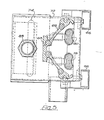
- the heating unit 4 is supported over the cabinet by a structure comprising end plates 44, each supported by an upright 6 which in turn is secured to a side of the cabinet 2.
- Each end plate is provided with two vertical slots 46, and the unit 4 is attached to the respective plates by bolts passing through the slots.
- the unit is intended to be arranged parallel to the belt l0 and, by fixing the bolts in the slots at different heights, at variable distance therefrom.
- the heating unit 4 comprises two elongate parallel channel members 66 supporting, at their ends, housings 68, 70, and terminating in end plates 72.
- Each of the end plates 72 has a horizontal slot 74 through which the bolts pass which have been described in relation to the vertical slots 46.
- the slot 74 is longer than the spacing of the slots 46 and allows adjustment of the location of the heating unit forwardly or rearwardly of the underlying cabinet 2.
- Each of the housings 68,70 encloses sockets 72 for the reception of the ends of two twin short-wave infra-red heating tubes 78,80, ceramic terminal blocks 74, 76 and an electric fan 79.
- Blocks 74 serve to connect the heating tubes to mains via a controller to be described below, whilst blocks 76 are for connecting the fans 79 to mains through a switch.
- the fans serve to draw air downwardly into the housings through openings 90 in the lids 92 for the cooling of the sockets and terminal blocks.
- the openings 90 are protected by guards 94.
- the heating tubes are arranged parallel to one another and are surmounted by a reflector 82 which is in the form of an elongate aluminium extrusion having three lengthwise rows of holes 83 for ventilation purposes.
- the reflector 82 is of formed sheet metal.
- the reflector is secured at its ends to the respective terminal housings 68, 70.
- the housings also provide support for the ends of a cylindrical conduit 85 which is mounted above the reflector and which carries electrical cables from one housing to the other.
- Housing 68 is provided with an entry socket 86 for input power cables and each housing has an earthing or grounding stud 88.
- a vertical safety screen 48 of expanded metal is fixed between the end plates 44 and a tinted, transparent screen 60 of toughened glass is removably supported in front of screen 48 by inclined arms 62 which in turn are tiltably supported by beam 64 which extends between the supports 6 at their upper ends.
- the control console 8 which stands at the side of cabinet 2 and is shown schematically, contains a triac l06 of which the input is provided by mains electricity and of which the output is connected to the heating tubes 78,80.
- the triac is operatively connected to the tachogenerator l04 so that the output potential of the triac fed to the heating tubes is directly related to the speed of the motor 50 and thus to the surface speed of the belts l0 and 30, which typically ranges between 0 and 8 m/min.
- the output of the triac can also be manually varied by means of a potentiometer to adjust the heat of the tubes to suit the fabric being handled.
- a length of knitted fabric comprising a lengthwise series of fabric portions linked together with a link-thread degradable by heat, is fed into the light nip between rollers 32 and 34 from the front of the cabinet so that the fabric emerging rearwardly of the rollers is carried on the upper reach of belt l0 towards the belt 30.
- the surface speed of the roller 32 is set at up to 20% less than the surface speed of the belts l0, 30 so that all portions of the fabric which are firmly linked to the portion held, for the time being, in the nip between rollers 32 and 34 lag behind the faster-moving belt l0, which thus slips forwardly of and below the fabric.
- the height of the roller 26 and thus the depth of the entry between the belts l0 and 30 is adjusted in accordance with the nature, and in particular of the thickness, of the fabric, in order that the belt 30 bears so lightly on the fabric as not to exert longitudinal tension on fabric thus held in the nip.
- the motor 50 is switched on to initiate the motion of the rollers and belts, and the fabric to be separated is fed between rollers 32 and 34.
- a speed-related potential is fed to the tubes 78, 80, so that they generate heat in direct relation to the rate of the fabric advancement through the nip between rollers 32 and 34 and over belt l0 in the direction of arrow l8.
- the steam box 38 is also operated by connecting it to the steam source referred to above and adjusting the pressure transmitted thereto to about 0.5 atmospheres. Steam passes out of the box through the perforations therein, penetrates the belt l0, and thus reaches the fabric.
- the blower l02 is also switched on so that the steam is discharged from the fabric by a current of air as it passes under roller 30.
- the radiant heat generated by unit 4 and falling on the fabric is intended on the one hand to degrade the material of the link threads so much that it loses its coherence, and on the other hand to cause no damage to the fabric portions.
- This objective is primarily attained by the control of the output of the tubes in accordance with the speed of the fabric so that fabric remaining under the tubes for a longer period receives heat energy at a lower rate, whilst more intense heat is fed to fabrics passing more quickly through the apparatus.
- the tubes respond very quickly to the electrical input, so that any slowing of the movement of the fabric results in a rapid reduction of radiant heat received by the fabric, and unwanted damage is thereby avoided.
- conventional devices may be added to detect a breakage of any of the drive belts l08, ll0 ll2 and ll4, and consequently to isolate the tubes.
- a radiation pyrometer may be mounted above the belt 30 to measure radiation from the heated fabric and to operate a switch to break the electrical connection to the tubes in the event of the temperature of the fabric becoming excessive.
Landscapes
- Engineering & Computer Science (AREA)
- Textile Engineering (AREA)
- Treatment Of Fiber Materials (AREA)
- Knitting Of Fabric (AREA)
Applications Claiming Priority (2)
| Application Number | Priority Date | Filing Date | Title |
|---|---|---|---|
| GB8608183 | 1986-04-03 | ||
| GB868608183A GB8608183D0 (en) | 1986-04-03 | 1986-04-03 | Knitted fabric separating machines |
Publications (2)
| Publication Number | Publication Date |
|---|---|
| EP0240358A2 true EP0240358A2 (de) | 1987-10-07 |
| EP0240358A3 EP0240358A3 (de) | 1987-12-09 |
Family
ID=10595631
Family Applications (1)
| Application Number | Title | Priority Date | Filing Date |
|---|---|---|---|
| EP87302921A Withdrawn EP0240358A3 (de) | 1986-04-03 | 1987-04-03 | Maschine zum Trennen von Strickwaren |
Country Status (2)
| Country | Link |
|---|---|
| EP (1) | EP0240358A3 (de) |
| GB (2) | GB8608183D0 (de) |
Cited By (2)
| Publication number | Priority date | Publication date | Assignee | Title |
|---|---|---|---|---|
| EP0427933A1 (de) * | 1989-11-15 | 1991-05-22 | Vaupel Textilmaschinen Kg | Verfahren und Vorrichtung zur Herstellung eines durch Figurschüsse gemusterten textilen Bandes, insbesondere eines Etikettenbandes, aus einer Breitbahn mit schmelzfähigem Fadenwerkstoff |
| WO2007069285A1 (en) * | 2005-12-16 | 2007-06-21 | Mirco Magnani | Automatic device for finishing semifinished products by knitting |
Families Citing this family (1)
| Publication number | Priority date | Publication date | Assignee | Title |
|---|---|---|---|---|
| US5353486A (en) * | 1992-11-13 | 1994-10-11 | Minnesota Mining And Manufacturing Company | Narrow fiberglass knit tape |
Citations (5)
| Publication number | Priority date | Publication date | Assignee | Title |
|---|---|---|---|---|
| US2969580A (en) * | 1958-12-04 | 1961-01-31 | Shawmut Inc | Method of separating a continuous series of knit articles |
| DE2056210A1 (de) * | 1970-11-16 | 1972-05-31 | Schiesser Ag, 7760 Radolfzell | Verfahren und Vorrichtung zum Trennen von Warenlängen |
| US3908250A (en) * | 1972-06-23 | 1975-09-30 | Oxford Industries | Garment production process |
| FR2373976A1 (fr) * | 1976-12-16 | 1978-07-13 | Dim Rosy | Procede de production en continu d'articles de bonneterie tels que des chaussettes, bas et mi-bas et machine pour la mise en oeuvre du procede |
| EP0040036A1 (de) * | 1980-05-06 | 1981-11-18 | Hirohisa Dei | Verfahren zur Herstellung von Strickwaren |
Family Cites Families (8)
| Publication number | Priority date | Publication date | Assignee | Title |
|---|---|---|---|---|
| GB707322A (en) * | 1950-12-29 | 1954-04-14 | William Franklin & Son Ltd | An improved method of and means for finishing fabrics |
| GB840535A (en) * | 1958-01-27 | 1960-07-06 | Millville Mfg Co | Method and machine for forming textile articles having selvage |
| US3499231A (en) * | 1964-06-23 | 1970-03-10 | Fostoria Fannon Inc | A fast automatic infrared drying and fusing apparatus for a high melt coating on an easily combustible web |
| ZA711340B (en) * | 1970-03-19 | 1972-10-25 | Wiggins Teape Res Dev | Improvements in methods and apparatus for drying sheet material |
| JPS5241370B2 (de) * | 1973-09-14 | 1977-10-18 | ||
| CA1052994A (en) * | 1976-10-13 | 1979-04-24 | B And K Machinery International Limited | Convection oven and method of drying solvents |
| DE2966649D1 (en) * | 1979-12-28 | 1984-03-15 | Ichikin Kogyosha Kk | Method and apparatus for aftertreatment of textile sheet by application of microwaves |
| DE3522695C1 (de) * | 1985-06-25 | 1987-01-15 | Monforts Gmbh & Co A | Infrarottrockner |
-
1986
- 1986-04-03 GB GB868608183A patent/GB8608183D0/en active Pending
-
1987
- 1987-04-02 GB GB08707860A patent/GB2189421A/en not_active Withdrawn
- 1987-04-03 EP EP87302921A patent/EP0240358A3/de not_active Withdrawn
Patent Citations (5)
| Publication number | Priority date | Publication date | Assignee | Title |
|---|---|---|---|---|
| US2969580A (en) * | 1958-12-04 | 1961-01-31 | Shawmut Inc | Method of separating a continuous series of knit articles |
| DE2056210A1 (de) * | 1970-11-16 | 1972-05-31 | Schiesser Ag, 7760 Radolfzell | Verfahren und Vorrichtung zum Trennen von Warenlängen |
| US3908250A (en) * | 1972-06-23 | 1975-09-30 | Oxford Industries | Garment production process |
| FR2373976A1 (fr) * | 1976-12-16 | 1978-07-13 | Dim Rosy | Procede de production en continu d'articles de bonneterie tels que des chaussettes, bas et mi-bas et machine pour la mise en oeuvre du procede |
| EP0040036A1 (de) * | 1980-05-06 | 1981-11-18 | Hirohisa Dei | Verfahren zur Herstellung von Strickwaren |
Cited By (2)
| Publication number | Priority date | Publication date | Assignee | Title |
|---|---|---|---|---|
| EP0427933A1 (de) * | 1989-11-15 | 1991-05-22 | Vaupel Textilmaschinen Kg | Verfahren und Vorrichtung zur Herstellung eines durch Figurschüsse gemusterten textilen Bandes, insbesondere eines Etikettenbandes, aus einer Breitbahn mit schmelzfähigem Fadenwerkstoff |
| WO2007069285A1 (en) * | 2005-12-16 | 2007-06-21 | Mirco Magnani | Automatic device for finishing semifinished products by knitting |
Also Published As
| Publication number | Publication date |
|---|---|
| GB8608183D0 (en) | 1986-05-08 |
| EP0240358A3 (de) | 1987-12-09 |
| GB8707860D0 (en) | 1987-05-07 |
| GB2189421A (en) | 1987-10-28 |
Similar Documents
| Publication | Publication Date | Title |
|---|---|---|
| US3605280A (en) | Combination drying and tentering machine | |
| KR900000539A (ko) | 열을 공급하여 꿀로 오염된 면섬유군의 점착성을 줄이는 방법 및 장치 | |
| KR101874349B1 (ko) | 섬유원단 후가공 재단 기능을 가진 가공장치 | |
| EP0240358A2 (de) | Maschine zum Trennen von Strickwaren | |
| SE446106B (sv) | Anleggning for hantering av foliematerial vid en konfektioneringsmaskin | |
| CA1037986A (en) | Tension control for continuous lenghts of textile material | |
| US5003670A (en) | Apparatus for reducing the stickiness of cotton flocks | |
| JP3181891B2 (ja) | 筒状編地の処理方法とその装置 | |
| US4935077A (en) | Process for bonding cellulosic nonwovens with thermoplastic fibers using infrared radiation | |
| US3879816A (en) | Machine for finishing textile material, especially knitted fabric, in a continuous manner | |
| EP1057921B1 (de) | Vorrichtung sowie Verfahren zum thermischen Fixieren von Maschenwaren in Schlauchform | |
| US3438139A (en) | Apparatus for setting fabric | |
| US4722121A (en) | Apparatus for separating knitted garment pieces | |
| US3696522A (en) | Drier for paper webs | |
| US3909890A (en) | Method for heat-treating knitted fabric in tubular distended form | |
| US3470636A (en) | Laundry flatwork feeder | |
| US2597490A (en) | Apparatus for treating textile materials | |
| US3961400A (en) | Perforated drum drier | |
| US4759106A (en) | Method for knitting and separating garment pieces | |
| US2635872A (en) | Means for feeding lengths of material between series of rollers | |
| USRE29267E (en) | Apparatus for straightening fabric | |
| US3098264A (en) | Multiple swift textile waste tearing machine | |
| GB1178270A (en) | An Apparatus for the Continuous Finish Treatment of Knitted Fabric Webs. | |
| US3818607A (en) | Process and apparatus for the treatment of material lengths | |
| CN212227632U (zh) | 一种用于缝被机的灭菌干燥装置 |
Legal Events
| Date | Code | Title | Description |
|---|---|---|---|
| PUAI | Public reference made under article 153(3) epc to a published international application that has entered the european phase |
Free format text: ORIGINAL CODE: 0009012 |
|
| AK | Designated contracting states |
Kind code of ref document: A2 Designated state(s): BE DE FR IT LU NL |
|
| PUAL | Search report despatched |
Free format text: ORIGINAL CODE: 0009013 |
|
| AK | Designated contracting states |
Kind code of ref document: A3 Designated state(s): BE DE FR IT LU NL |
|
| STAA | Information on the status of an ep patent application or granted ep patent |
Free format text: STATUS: THE APPLICATION IS DEEMED TO BE WITHDRAWN |
|
| 18D | Application deemed to be withdrawn |
Effective date: 19880610 |
|
| RIN1 | Information on inventor provided before grant (corrected) |
Inventor name: CLARKE, FREDERIC |