EP0240048B1 - Umrissbearbeitungsmaschine - Google Patents
Umrissbearbeitungsmaschine Download PDFInfo
- Publication number
- EP0240048B1 EP0240048B1 EP87200375A EP87200375A EP0240048B1 EP 0240048 B1 EP0240048 B1 EP 0240048B1 EP 87200375 A EP87200375 A EP 87200375A EP 87200375 A EP87200375 A EP 87200375A EP 0240048 B1 EP0240048 B1 EP 0240048B1
- Authority
- EP
- European Patent Office
- Prior art keywords
- working
- reaction force
- load sensor
- axes
- tool
- Prior art date
- Legal status (The legal status is an assumption and is not a legal conclusion. Google has not performed a legal analysis and makes no representation as to the accuracy of the status listed.)
- Expired - Lifetime
Links
Images


Classifications
-
- B—PERFORMING OPERATIONS; TRANSPORTING
- B23—MACHINE TOOLS; METAL-WORKING NOT OTHERWISE PROVIDED FOR
- B23Q—DETAILS, COMPONENTS, OR ACCESSORIES FOR MACHINE TOOLS, e.g. ARRANGEMENTS FOR COPYING OR CONTROLLING; MACHINE TOOLS IN GENERAL CHARACTERISED BY THE CONSTRUCTION OF PARTICULAR DETAILS OR COMPONENTS; COMBINATIONS OR ASSOCIATIONS OF METAL-WORKING MACHINES, NOT DIRECTED TO A PARTICULAR RESULT
- B23Q17/00—Arrangements for observing, indicating or measuring on machine tools
- B23Q17/22—Arrangements for observing, indicating or measuring on machine tools for indicating or measuring existing or desired position of tool or work
- B23Q17/2233—Arrangements for observing, indicating or measuring on machine tools for indicating or measuring existing or desired position of tool or work for adjusting the tool relative to the workpiece
-
- B—PERFORMING OPERATIONS; TRANSPORTING
- B24—GRINDING; POLISHING
- B24B—MACHINES, DEVICES, OR PROCESSES FOR GRINDING OR POLISHING; DRESSING OR CONDITIONING OF ABRADING SURFACES; FEEDING OF GRINDING, POLISHING, OR LAPPING AGENTS
- B24B19/00—Single-purpose machines or devices for particular grinding operations not covered by any other main group
- B24B19/20—Single-purpose machines or devices for particular grinding operations not covered by any other main group for grinding dies
-
- B—PERFORMING OPERATIONS; TRANSPORTING
- B24—GRINDING; POLISHING
- B24B—MACHINES, DEVICES, OR PROCESSES FOR GRINDING OR POLISHING; DRESSING OR CONDITIONING OF ABRADING SURFACES; FEEDING OF GRINDING, POLISHING, OR LAPPING AGENTS
- B24B49/00—Measuring or gauging equipment for controlling the feed movement of the grinding tool or work; Arrangements of indicating or measuring equipment, e.g. for indicating the start of the grinding operation
- B24B49/16—Measuring or gauging equipment for controlling the feed movement of the grinding tool or work; Arrangements of indicating or measuring equipment, e.g. for indicating the start of the grinding operation taking regard of the load
-
- G—PHYSICS
- G05—CONTROLLING; REGULATING
- G05B—CONTROL OR REGULATING SYSTEMS IN GENERAL; FUNCTIONAL ELEMENTS OF SUCH SYSTEMS; MONITORING OR TESTING ARRANGEMENTS FOR SUCH SYSTEMS OR ELEMENTS
- G05B19/00—Programme-control systems
- G05B19/02—Programme-control systems electric
- G05B19/18—Numerical control [NC], i.e. automatically operating machines, in particular machine tools, e.g. in a manufacturing environment, so as to execute positioning, movement or co-ordinated operations by means of programme data in numerical form
- G05B19/41—Numerical control [NC], i.e. automatically operating machines, in particular machine tools, e.g. in a manufacturing environment, so as to execute positioning, movement or co-ordinated operations by means of programme data in numerical form characterised by interpolation, e.g. the computation of intermediate points between programmed end points to define the path to be followed and the rate of travel along that path
-
- G—PHYSICS
- G05—CONTROLLING; REGULATING
- G05B—CONTROL OR REGULATING SYSTEMS IN GENERAL; FUNCTIONAL ELEMENTS OF SUCH SYSTEMS; MONITORING OR TESTING ARRANGEMENTS FOR SUCH SYSTEMS OR ELEMENTS
- G05B2219/00—Program-control systems
- G05B2219/30—Nc systems
- G05B2219/49—Nc machine tool, till multiple
- G05B2219/49362—Tool, probe at constant height to surface during machining
-
- Y—GENERAL TAGGING OF NEW TECHNOLOGICAL DEVELOPMENTS; GENERAL TAGGING OF CROSS-SECTIONAL TECHNOLOGIES SPANNING OVER SEVERAL SECTIONS OF THE IPC; TECHNICAL SUBJECTS COVERED BY FORMER USPC CROSS-REFERENCE ART COLLECTIONS [XRACs] AND DIGESTS
- Y10—TECHNICAL SUBJECTS COVERED BY FORMER USPC
- Y10T—TECHNICAL SUBJECTS COVERED BY FORMER US CLASSIFICATION
- Y10T409/00—Gear cutting, milling, or planing
- Y10T409/30—Milling
- Y10T409/304536—Milling including means to infeed work to cutter
- Y10T409/304648—Milling including means to infeed work to cutter with control means energized in response to activator stimulated by condition sensor
- Y10T409/304704—In response to cutter or cutter carriage
-
- Y—GENERAL TAGGING OF NEW TECHNOLOGICAL DEVELOPMENTS; GENERAL TAGGING OF CROSS-SECTIONAL TECHNOLOGIES SPANNING OVER SEVERAL SECTIONS OF THE IPC; TECHNICAL SUBJECTS COVERED BY FORMER USPC CROSS-REFERENCE ART COLLECTIONS [XRACs] AND DIGESTS
- Y10—TECHNICAL SUBJECTS COVERED BY FORMER USPC
- Y10T—TECHNICAL SUBJECTS COVERED BY FORMER US CLASSIFICATION
- Y10T409/00—Gear cutting, milling, or planing
- Y10T409/30—Milling
- Y10T409/306664—Milling including means to infeed rotary cutter toward work
- Y10T409/306776—Axially
- Y10T409/306832—Axially with infeed control means energized in response to activator stimulated by condition sensor
- Y10T409/306888—In response to cutter condition
-
- Y—GENERAL TAGGING OF NEW TECHNOLOGICAL DEVELOPMENTS; GENERAL TAGGING OF CROSS-SECTIONAL TECHNOLOGIES SPANNING OVER SEVERAL SECTIONS OF THE IPC; TECHNICAL SUBJECTS COVERED BY FORMER USPC CROSS-REFERENCE ART COLLECTIONS [XRACs] AND DIGESTS
- Y10—TECHNICAL SUBJECTS COVERED BY FORMER USPC
- Y10T—TECHNICAL SUBJECTS COVERED BY FORMER US CLASSIFICATION
- Y10T409/00—Gear cutting, milling, or planing
- Y10T409/30—Milling
- Y10T409/306664—Milling including means to infeed rotary cutter toward work
- Y10T409/307224—Milling including means to infeed rotary cutter toward work with infeed control means energized in response to activator stimulated by condition sensor
- Y10T409/30728—In response to cutter condition
-
- Y—GENERAL TAGGING OF NEW TECHNOLOGICAL DEVELOPMENTS; GENERAL TAGGING OF CROSS-SECTIONAL TECHNOLOGIES SPANNING OVER SEVERAL SECTIONS OF THE IPC; TECHNICAL SUBJECTS COVERED BY FORMER USPC CROSS-REFERENCE ART COLLECTIONS [XRACs] AND DIGESTS
- Y10—TECHNICAL SUBJECTS COVERED BY FORMER USPC
- Y10T—TECHNICAL SUBJECTS COVERED BY FORMER US CLASSIFICATION
- Y10T409/00—Gear cutting, milling, or planing
- Y10T409/30—Milling
- Y10T409/30784—Milling including means to adustably position cutter
- Y10T409/307952—Linear adjustment
- Y10T409/308008—Linear adjustment with control for adjustment means responsive to activator stimulated by condition sensor
Definitions
- This invention relates to a profile working machine such as die-finishing grinding machine, ceramics- working grinding machine, three-dimensional milling machine or the like.
- the working or machining is in many instances conducted by mounting a ball end mill or the like on an NC milling machine or a machining center. After such working or machining is performed, cutting tool marks are caused to remain on the thus-finished die. Hence, it cannot be used as a die without any additional machining or treatment. It has thus been required to add a further step in which such cutting tool marks are removed with a shafted grinder held by a hand while observing them.
- Such a manual work has prevented full automation of machining steps in profile machining work, thereby imposing a serious limitation on the profile machining work.
- FIG. 9 is a side view of a working tool and a work.
- a table 1 of a working machine a work 2 fixedly held on the table 1, and a working tool 3 for grinding the work 2.
- Letter T indicates a point of action (working point) by the working tool 3 on the work 2
- letter F designates a working reaction force exerted on the working tool 3.
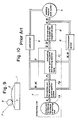
- FIG 10 is a system diagram of the profile working machine.
- a working tool/work system 5 which includes the table 1 and working tool 3, and a load sensor 6 for detecting a force (with force components and moment components applied respectively along and about respective axes) to the working tool 3.
- Designated as letter F are the force components detected by the load sensor 6, while indicated as letter M are the moment components detected by the load sensor 6.
- Numeral 7 indicates a computing unit for control, which is composed of a unit 7A for outputting data on the shape of each working tool (hereinafter called “working tool shape data output unit 7A"), a unit 7B for calculating each working point and tangential plane (hereinafter called “working point/tangential plane calculation unit 7B), and a unit 7C for computing each working point and working reaction force (hereinafter called “working point/working reaction force computing unit 7C).
- the working tool shape data output unit 7A outputs, as a signal, data S on the shape of the working tool 3, for example, a ball having a radius of such and such millimeters or a cylinder having a radius of such and such millimeters and a length of such and such millimeters.
- the working point/tangential plane calculation unit 7B calculates the position of the working point T and the tangential plane P t at the working point T on the basis of the data S output from the working tool shape data output unit 7A and the force F and moment M detected by the load sensor 6.
- the working point/working reaction force computing unit 7C judges, based on the working reaction force F detected by the load sensor 6 and the working point T and tangential plane P t calculated by the working point/tangential plane calculation unit 7B, whether the working reaction force F is suitable or not for the working point T and tangential plane P t , and outputs a position signal X and spatial orientation signal a to correct, if necessary, the working reaction force F.
- Designated as numeral 8 is a drive and control system for respective axes, which operates upon input of the signals X, .
- the drive and control system 8 controls the relative positions X and relative spatial orientations between the table 1 and working tool 3.
- Numeral 9 indicates displacement sensors for detecting the present positions and spatial orientations of the table 1 and working tool 3, and outputs the so-detected position signals X and spatial orientation signals 9.
- the working point T and tangential plane P t are always calculated by the working point/tangential plane calculation unit 7B, and a judgement is made to determine whether the working point T is located at a point where the working tool 3 can perform machining.
- a judgement is made by the working point/working reaction force computing unit 7C to determine whether the present working reaction force F is suitable for the working point T and tangential plane P t .
- the present working reaction force F is suitable, the working is continued as is.
- computation is performed to determine how the relative positions X and relative spatial orientations of the working tool 3 and table 1 should be corrected to adjust the working reaction force F to suitable values.
- the working point/working reaction force computing unit 7C gives commands X, (HJ) to the drive and control system 8 for the respective axes.
- the commands may generally be input in the form of target relative positions X and target relative spatial orientations or in the form of displacements AX, A@ over which the relative positions and relative spatial orientations should be corrected from the present state.
- the above-described profile working machine can perform machining copying the profile, namely, the curved surface of the work 2 while always maintaining the working reaction force exerted on the working tool 3 at the most suitable value. Therefore, the profile working machine allows to conduct profile machining work automatically under ideal working conditions.
- the coordinate system of the working tool 3 is usually different from that of the load sensor 6. No particular correlation is contemplated either between both coordinate systems in the above-described conventional profile working machine. Therefore, the each load component detected by the load sensor is based on the coordinate system of the load sensor 6. In order to determine the working reaction force exerted on the working tool 3, computation is required to transform the value detected by the load sensor 6 into a value under the coordinate system of the working tool 3. Since this computation is complex, the computing unit requires lots of time for its design and fabrication and correspondingly, a rather long period of time is needed to perform the computation.
- the above computation includes a computation step in which the working point T and tangential plane P t are determined.
- This computation is more complex than the above-mentioned computation for the transformation of the coordinate system.
- One example of this computation is described in European Patent Application EP-A-0 177 084. It will be clearly understood from said example how complex the computation is.
- the exemplified computation is limited to a simple example in which the working tool 3 is spherical. Where the working tool 3 has various shapes other than sphere, the computation of the working point T and tangential plane P t will apparently become more complex.
- the computing unit of the working point T and tangential plane P t requires still more manpower and time for its design and fabrication and at the same time, their computation requires substantial time.
- the conventional profile working machine contains, in its control loop, a computation step which requires significant computing time.
- the conventional profile working machine is therefore accompanied by such drawbacks that its computing unit requires a high fabrication cost and since its responsibility, which is needed for the control of forces, is reduced, it cannot achieve any high working speed.
- An object of this invention is to provide a profile working machine which is free of the above-described drawbacks of the prior art and can improve the working speed and responsibility.
- the present invention provides a profile working machine equipped with a support portion for holding a work thereon, a working tool for machining the work and a drive and control system for controlling the relative spatial displacements between the support portion and the working tool and adapted to machine the work into a desired profile, comprising:
- a working reaction force in suitable working conditions has a specific magnitude and direction relative to the tangential plane P t at the working point T on a curved surface to be machined.
- Such working reaction force will hereinafter be called “the suitable working reaction force” for the sake of brevity.
- the actual working reaction force varies depending on working conditions.
- the magnitude of the suitable working reaction force is stored resolved in a load vector value in each of the three directions of a coordinate system fixed on the load sensor.
- a working reaction force is detected in three vector values by the load sensor during the working operation. Each set of detected vector values is compared with the set of vector values stored in the memory unit.
- the suitable working reaction force is set, the set of vector values detected by the load sensor and stored in the memory unit, a set of vector values of an actual working reaction force detected by the load sensor in the course of a working operation is compared with the set of stored vector values, and the relative positions and relative spatial orientations of the table and working tool support mechanism are then controlled on the basis of the deviation of the detected values from the stored values so as to make the detected values equal to the stored values as described above, keeping, relative to the load sensor, the spatial orientation of the actual working reaction force identical to the spatial orientation of the suitable working reaction force. It is therefore possible to omit computing steps substantially, to reduce the cost for the fabrication of the unit required for computation and to increase the working speed and responsibility, so that the working capacity can be improved.
- the expression “the direction is constant relative to the working surface” in case of profile working should read that "the direction is constant relative to the tangential plane for the curved surface, which is to be worked, at the working point as a point of contact between the working tool and work".
- the former expression will be used instead of the latter expression for the sake of simplicity.
- the above description of the empirical fact is now supplemented. If grinding conditions such as material to be ground, working tool, feeding speed and depth of grinding are kept constant, the direction of the actual working reaction force is automatically set as long as the magnitude of the working reaction force is controlled to have the suitable value. In other words, suitable working conditions can be maintained as long as the magnitude of the actual working reaction force is controlled solely.
- the present invention has now materialized a machine capable of performing smooth profile grinding while always maintaining ideal working conditions for a momentarily-changing curved surface.
- FIG. 1 is a system diagram of a profile working machine according to the preferred embodiment of this invention.
- parts of structure similar to their corresponding parts shown in Figure 10 are identified by like reference numerals and their description is omitted.
- Numeral 10 indicates a computing unit for a constant load vector control.
- the computing unit 10 is composed of a memory unit 11, deviation computing unit 12 and displacement computing unit 13.
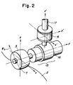
- FIG 2 is a perspective view of the working tool/work system and load sensor, both, illustrated in Figure 1.
- a work 2 fixed on a table and a working tool 3. They are the same as those depicted in Figure 9.
- Designated at numeral 6 is the load sensor shown in Figure 1.
- the load sensor 6 serves to detect force components and moment components along and about the respective axes which extend at right angles.
- a working tool support mechanism 15 for holding and driving the working tool 3
- a coupling member 16 coupling the load sensor 6 and working tool support mechanism 15 together
- a connecting member 17 connecting the unillustrated main body of the working machine and the load sensor 6 to each other.
- the illustrated embodiment is different from the conventional machine in that the conventional machine requires a computing step for the transformation of each coordinate system and another computing step for computing the working point T and tangential plane P t while these computing steps are not needed for the illustrated embodiment of this invention. These differences will next be described with reference to Figure 1 and Figure 2.
- the load sensor 6 detects load components corresponding to the working reaction force F o with respect to the respective x', y' and z' axes.
- load components force components along the x', y' and z' axes will now be identified respectively by F xo ',F yo ' and Fzo' while moment components about the x', y' and z' axes will hereinafter be identified respectively by M XO , Myo and MZO .
- the above force components F xo ,F yo ',F zo and moment components M xo ',M yo ',M zo are first of all stored in the memory unit 11 of the computing unit constant load vector control 10.
- the force components F x ,F y ',F z and moment components F x ,F y ',F z of each actual working reaction force F detected respectively along and about the x', y' and z' axes by the load sensor 6 are compared, at the deviation computing unit 12, respectively with the above-mentioned force components F xo ', F yo ', F zo ' and moment components M xo ',M yo ',M zo ' stored in the memory unit 11, whereby the deviations of the former force and moment components from the latter force and moment components are calculated.
- the respective deviations calculated at the deviation computing unit 12 are then input to the displacement computing unit 13, where based on the thus-input deviations and the present relative positions and relative spatial orientations of the table 1 and working tool support mechanism 15 detected by the displacement sensors 9, computation is performed to determine how much the table 1 and working tool support mechanism 15 should be moved from their present positions and spatial orientations to reduce the deviations to 0.
- Values computed at the displacement computing unit 13 are output to the drive and control system 8 for the respective axes. In accordance with these values, the relative positions and spatial orientations of the table 1 and working tool support mechanism 15 are controlled to reduce the above-described deviations to 0.
- the working reaction force is maintained constant in direction relative to the curved surface under working while maintaining its initial value F o , and at the same time, the direction of the working reaction force and the spatial orientation of the load sensor 6 is always maintained constant in the same relation as the initial relation. In this manner, the profile working operation is performed smoothly.
- the displacement computing unit 13 serves to compute how the relative positions X and relative spatial orientations (the combination of these two vectors will hereinafter be identified by a vector D) between the table 1 and working tool support mechanism 15 should be corrected from their present positions and spatial orientations in order to reduce the deviation of the working reaction force to 0.
- the displacement correcting value AD can be represented by the following linear approximation:
- a determinant expressed in terms of the individual elements of the approximation (1) will next be described as a determinant (2).
- the correcting values ⁇ x , ⁇ y , ⁇ z and the correcting values ⁇ x , ⁇ y , ⁇ z are collectively identified by ⁇ X and ⁇ respectively.
- the values C 11 -C 66 change depending on conditions such as the rigidity of the working machine itself, the rigidity of the work 2 to be worked, the present position and spatial orientation of the working machine, etc. They can be determined when these conditions are specifically indicated.
- control is performed in this embodiment in such a manner that the detected values F x' ,F y' ,F z' ,M x' ,M y' ,M z' remain always equal to their corresponding constant values F xo ',F yo ',F zo ',M xo ',M yo ',M zo '.
- This means that the position and spatial orientation of the load sensor 6 are maintained constant relative to the direction and working point T of the prescribed suitable working reaction force F o .
- the working point T is always maintained at a point satisfying a certain constant positional relation relative to the working tool support mechanism 15, because the relative positional relation between the working tool support mechanism 15 holding the working tool 3 in place thereon and the load sensor 6 is constant. It is therefore possible to avoid the need for the computation of the working point T and hence to omit the computing step for the working point T, so long as control is effected in the above-described manner. It is also unnecessary to compare the actual working reaction force to the prescribed suitable one in the coordinate system of the working tool 3. This eliminates the computation for the transformation of the actual working reaction force detected as values in the coordinate system of the load sensor 6 to those in the coordinate system of the working tool 3, thereby permitting the omission of the computing step for the transformation.
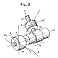
- FIG 3 is a perspective view of a working tool, work and load sensor according to the first specific example of this embodiment.
- parts of structure similar to their corresponding parts shown in Figure 2 are identified by like reference numerals and letters and their description is omitted.
- the relation between the load sensor 6 and the suitable working reaction force F o in this specific example is chosen in such a way that one of the coordinate axes of the load sensor 6 (the z' axis in the illustrated example) extends in parallel with the direction of the working reaction force F o .
- the force components (F xo ', F yo ', F zo ') and moment components (M xo ',M yo ',M zo ') detected by the load sensor 6 upon exertion of the working reaction force F o on the working point T are obviously values conforming the coordinate axes x',y',z' shown in Figure 3. These values are stored in the memory unit 11 of the computing unit for constant load vector control 10.
- the force components (F xo ',F yo ',F zo ') and moment components (M xo ',M yo ',M zo ') detected by the load sensor 6 are compared, at the deviation computing unit 12, axis by axis with their corresponding values stored in the memory unit 11 to compute their differences.
- the so-computed deviations are input to the displacement computing unit 13 to calculate the relative positions and relative spatial orientations of the table 1 and working tool support mechanism 15 for their correction.
- the respective axes are then driven by way of the drive and control system 8 for the respective axes.
- the table 1 and working tool support mechanism 15 are controlled in such a manner that the z' axis of the load sensor 6 is always maintained coincident with the suitable working reaction force F o .
- the force components F xo ',F yo ' and moment components M yo ',M zo ' detected by the load sensor 6 upon exertion of the working reaction force F o are 0 and their corresponding values stored in the memory unit 11 are also 0. Accordingly, the force components Fx',Fy' and moment components MY,MZ detected by the load sensor 6 in the course of the working operation are deviations by themselves. It is thus unnecessary to perform computation with respect to these components at the deviation computing unit 12, thereby simplifying the computation.
- the present embodiment makes it possible to increase the sensitivity with respect to moments about the y' and z' axes so that a significant contribution has been brought about to the control accuracy.
- FIGs 4 and 5 are respectively front and side views of a working and load sensor according to the second specific example of the present embodiment.
- parts of structure similar to their corresponding parts shown in Figure 2 are identified by like reference numerals and letters.
- Numerals 18,18' indicate load sensor support members which are connected respectively to the shaft of the working tool 3 and the coupling member 16 and support the load sensor 6.
- the load sensor 6 and suitable working reaction force F o are chosen in such a relation that one (the z' axis) of the coordinate axes of the load sensor 6 coincides with the direction of the suitable working reaction force F o .
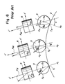
- Figure 6 shows how a working operation making use of the conventional machine proceeds.
- the drawing illustrates the manner of progress of the working operation to positions P 1 ,P 2 ,P 3 in order.
- working points T 1 , T 2 , T 3 at the positions P l ,P 2 ,P 3 and central points 0 1 ,0 2 ,0 3 of the working tool 3 at the positions P l ,P 2 ,P 3 .
- control is performed to maintain the suitable working reaction force F o and its direction ⁇ o (the angle between the normal at the working point T and the direction of the working reaction force F o ) constant relative to the curved surface 2 under the working operation while not changing the spatial orientation of the load sensor 6.
- the angle a between the z'-axis of the load sensor 6 and the normal at the working point T (the angle a is considered to be a parameter representing a relative direction of the tangential plane to the load sensor 6 because the tangential plane is perpendicular to O i T i at the working point T i ) changes.
- Figure 7 shows the manner of working at a certain working position in the course of a working operation which is being performed in the same manner as that depicted in Figure 6. Let's now assume:
- the working reaction force F and its direction ⁇ can be determined for the first time by ascertaining the position of the working point T and the tangential plane (angle a) at the working point T while making use of the detected load information F x ' ' F z ' ' M y ' in their entirety.
- the deviation AF of the working reaction force and the deviation ⁇ of its direction are:
- the conventional machine needs such cumbersome computation as mentioned above to obtain the required deviations even in the simplest case having a degree of freedom with respect to three axes only.
- the complexity of computation apparently increases in a geometric series as the degree of freedom increases one axis by one axis.
- Such computation may itself be performed so long as it is done by those skilled in the art. If it is performed at the control and computing unit 7 of the conventional machine shown in Figure 10, a long computing time is required, the performance of the control is reduced, and the fabrication cost of the computing means increases.
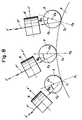
- Figure 8 shows the manner of progress of a working operation in the second specific example. Parts of structure and positions similar to their corresponding parts and positions as depicted in Figure 6 are identified by like reference numerals and letters. As will be understood immediately from the drawing, it is only necessary in this specific example to control the direction ⁇ o of the suitable working reaction force F o and the z'-axis in such a way that they are always coincided with each other.
- the complexity of the computation increases in a geometric series in the conventional machine as the degree of freedom increases.
- the computation is simplified further as the degree of freedom increases.
- the rated moment value is increased in view of the large moments, the rated force value has to be increased correspondingly. Small forces must thus be measured in the large measurement range, leading to a drawback that the control accuracy is reduced considerably. Since all moment components are detected with small values in the present specific example, it is feasible to determine the rated force value in accordance with the magnitudes of forces which occur actually. This improves the control accuracy and at the same time, permits use of a load sensor having a rated capacity smaller compared with the conventional method. The machine can therefore be fabricated at a lower cost.
- the machine of this invention allows to control greater loads with the same load sensor although the conventional machine does not permit application of large forces due to increased moments and the working capacity is considerably limited. Unlike the conventional machine, the machine of this invention permits the control of greater loads by using the same load sensor.
- the present specific example brings about the same effects as the second specific example and at the same time, increases the working capacity compared with the conventional machine equipped with the same load sensor.
- a load sensor having a smaller rated capacity it is feasible to improve the working accuracy and to construct the machine at a lower cost.
- the present embodiment can omit computing steps which have been considered to be indispensable in the conventional machine. It is therefore possible to reduce the fabrication cost for the part required for computation.
- the present embodiment has also brought about such additional effects that the computing speed can be shortened considerably and the responsibility can be improved. It is also possible to retain, without any problems, the characteristic feature that a work can be worked automatically while always maintaining the working reaction force at a suitable value.
- the present embodiment has another a further advantage that it permits use of a load sensor having a smaller rated capacity.
Landscapes
- Engineering & Computer Science (AREA)
- Mechanical Engineering (AREA)
- Computing Systems (AREA)
- Theoretical Computer Science (AREA)
- Human Computer Interaction (AREA)
- Manufacturing & Machinery (AREA)
- Physics & Mathematics (AREA)
- General Physics & Mathematics (AREA)
- Automation & Control Theory (AREA)
- Automatic Control Of Machine Tools (AREA)
- Numerical Control (AREA)
- Constituent Portions Of Griding Lathes, Driving, Sensing And Control (AREA)
- Machine Tool Sensing Apparatuses (AREA)
Claims (3)
Applications Claiming Priority (2)
| Application Number | Priority Date | Filing Date | Title |
|---|---|---|---|
| JP44165/86 | 1986-03-03 | ||
| JP61044165A JPH074765B2 (ja) | 1986-03-03 | 1986-03-03 | 曲面加工装置 |
Publications (3)
| Publication Number | Publication Date |
|---|---|
| EP0240048A2 EP0240048A2 (de) | 1987-10-07 |
| EP0240048A3 EP0240048A3 (en) | 1989-03-29 |
| EP0240048B1 true EP0240048B1 (de) | 1994-06-15 |
Family
ID=12683977
Family Applications (1)
| Application Number | Title | Priority Date | Filing Date |
|---|---|---|---|
| EP87200375A Expired - Lifetime EP0240048B1 (de) | 1986-03-03 | 1987-03-02 | Umrissbearbeitungsmaschine |
Country Status (4)
| Country | Link |
|---|---|
| US (1) | US4772161A (de) |
| EP (1) | EP0240048B1 (de) |
| JP (1) | JPH074765B2 (de) |
| DE (1) | DE3750050T2 (de) |
Families Citing this family (20)
| Publication number | Priority date | Publication date | Assignee | Title |
|---|---|---|---|---|
| US5157878A (en) * | 1987-03-19 | 1992-10-27 | Canon Kabushiki Kaisha | Polishing method with error correction |
| JP2977203B2 (ja) * | 1989-04-19 | 1999-11-15 | 株式会社東芝 | 研磨装置 |
| DE69028041T2 (de) * | 1989-05-17 | 1997-01-09 | Fujitsu Ltd | Profilsteuerungssystem für Roboter |
| US6205371B1 (en) * | 1990-08-11 | 2001-03-20 | Dieter Wolter-Doll | Method and apparatus for detecting machining flaws, especially caused by grinding machines |
| JP2838014B2 (ja) * | 1993-03-31 | 1998-12-16 | マツダ株式会社 | 研磨装置 |
| JP3497031B2 (ja) * | 1995-03-07 | 2004-02-16 | 日立建機株式会社 | 油圧ポンプ制御装置 |
| US5788435A (en) * | 1995-04-28 | 1998-08-04 | Mccarthy; John F. | Automated diamond cutter apparatus |
| JPH0997112A (ja) * | 1995-09-28 | 1997-04-08 | Toyota Motor Corp | 軌跡制御方法および装置 |
| EP0810497B1 (de) * | 1995-12-19 | 2002-12-18 | Hitachi Construction Machinery Co., Ltd. | Verfahren zur korrektur des ausgangsignals eines steuergerätes, steuergerät und steuergerät für hydraulikpumpe |
| US6934616B2 (en) * | 2002-12-17 | 2005-08-23 | Caterpillar Inc | System for determining an implement arm position |
| JP4435526B2 (ja) * | 2003-09-19 | 2010-03-17 | 独立行政法人理化学研究所 | 自由曲面精密加工ツール |
| DE102004003203A1 (de) * | 2004-01-22 | 2005-08-11 | Robert Bosch Gmbh | Elektro-Handwerkzeug mit optimiertem Arbeitsbereich |
| US20070033785A1 (en) * | 2005-08-09 | 2007-02-15 | Kohring Mark D | Ridge vent with biocidal source |
| JP5260139B2 (ja) * | 2008-05-22 | 2013-08-14 | 株式会社日進製作所 | 砥石接触感知方法およびその装置、ならびにホーニング加工方法およびホーニング盤 |
| US8550876B2 (en) * | 2011-08-08 | 2013-10-08 | Apple Inc. | Force-controlled surface finishing through the use of a passive magnetic constant-force device |
| CN114127659B (zh) | 2019-07-18 | 2024-02-27 | 株式会社安川电机 | 控制系统、控制方法以及非易失性存储器件 |
| WO2021009903A1 (ja) | 2019-07-18 | 2021-01-21 | 株式会社安川電機 | ロボットシステム、ロボットの制御方法、サーボシステム |
| JP7294448B2 (ja) * | 2019-11-27 | 2023-06-20 | 株式会社安川電機 | 研削システム、補正量推定装置、コンピュータプログラム及び研削方法 |
| CN112720060B (zh) * | 2020-12-18 | 2022-08-05 | 湖北三江航天红阳机电有限公司 | 一种双型线曲面窄长涵道零件加工基准确定方法 |
| CN118357784B (zh) * | 2024-04-24 | 2024-10-15 | 力鼎智能装备(青岛)集团有限公司 | 一种基于人工智能的加工设备运行监控系统 |
Family Cites Families (12)
| Publication number | Priority date | Publication date | Assignee | Title |
|---|---|---|---|---|
| US3548172A (en) * | 1964-08-24 | 1970-12-15 | Bendix Corp | Adaptive control system for numerically controlled machine tool |
| CH486289A (de) * | 1968-08-08 | 1970-02-28 | Kistler Instrumente Ag | Elektrische Überwachungsanlage für Werkzeugmaschinen |
| JPS5114745B1 (de) * | 1970-03-24 | 1976-05-12 | ||
| US3665493A (en) * | 1970-03-30 | 1972-05-23 | Bendix Corp | Adaptive numerical control system for a machine tool |
| JPS4849088A (de) * | 1971-10-22 | 1973-07-11 | ||
| IT1078641B (it) * | 1976-09-14 | 1985-05-08 | Olivetti & Co Spa | Perfezionamenti a un centro di lavorazione autoadattativo per automazione programmabile |
| SU709325A1 (ru) * | 1977-12-19 | 1980-01-15 | Ордена Трудового Красного Знамени Экспериментальный Научно-Исследовательский Институт Металлорежущих Станков | Устройство автоматического контрол процесса резани |
| JPS5754054A (en) * | 1980-09-11 | 1982-03-31 | Toyoda Mach Works Ltd | Tool correcting apparatus provided with contact detector |
| JPS5834746A (ja) * | 1981-08-20 | 1983-03-01 | Toshiba Mach Co Ltd | ロ−ル研削盤の制御装置 |
| JPS5973272A (ja) * | 1982-10-18 | 1984-04-25 | Inoue Japax Res Inc | 数値制御研磨装置 |
| US4523409A (en) * | 1983-05-19 | 1985-06-18 | The Charles Stark Draper Laboratory, Inc. | Automatic contour grinding system |
| JPS6179549A (ja) * | 1984-09-28 | 1986-04-23 | Takaaki Nagao | 曲面加工装置 |
-
1986
- 1986-03-03 JP JP61044165A patent/JPH074765B2/ja not_active Expired - Lifetime
-
1987
- 1987-02-27 US US07/020,123 patent/US4772161A/en not_active Expired - Fee Related
- 1987-03-02 DE DE3750050T patent/DE3750050T2/de not_active Expired - Fee Related
- 1987-03-02 EP EP87200375A patent/EP0240048B1/de not_active Expired - Lifetime
Also Published As
| Publication number | Publication date |
|---|---|
| JPH074765B2 (ja) | 1995-01-25 |
| EP0240048A2 (de) | 1987-10-07 |
| US4772161A (en) | 1988-09-20 |
| EP0240048A3 (en) | 1989-03-29 |
| JPS62203756A (ja) | 1987-09-08 |
| DE3750050D1 (de) | 1994-07-21 |
| DE3750050T2 (de) | 1994-12-15 |
Similar Documents
| Publication | Publication Date | Title |
|---|---|---|
| EP0240048B1 (de) | Umrissbearbeitungsmaschine | |
| US4906907A (en) | Robot system | |
| US5509847A (en) | Control robot | |
| US5711697A (en) | Robot control system | |
| CN107498388B (zh) | 用于偏摆头的旋转中心校正装置 | |
| US5765976A (en) | Method of controlling the normal direction of the main shaft of the numerical control machine tool | |
| US5661654A (en) | Method of correcting error in mounting workpiece and apparatus therefor | |
| US20230347463A1 (en) | Control device, industrial machine, and control method | |
| JPH07205022A (ja) | 力制御ロボットの砥石摩耗補正方法 | |
| EP0364593B1 (de) | Werkzeugmaschine mit zwei hauptspindeln | |
| US5479353A (en) | System for correcting tool deformation amount | |
| US20180203429A1 (en) | Controller | |
| JPH05116081A (ja) | 力制御作業機械の重量・重心位置補正装置 | |
| JP3119308B2 (ja) | マシニングセンタ | |
| TWI638250B (zh) | 用於偏擺頭的旋轉中心校正裝置 | |
| JPH05318283A (ja) | 工具たわみ補正方式 | |
| JPH052455B2 (de) | ||
| JP2980933B2 (ja) | 衝撃試験片自動加工システム及び衝撃試験片自動加工方法 | |
| JPH03149171A (ja) | 産業用ロボットの工具軌跡制御装置 | |
| JP2508719B2 (ja) | 自動研削装置の位置補正方法およびその装置 | |
| JPH0357422Y2 (de) | ||
| JPH1158180A (ja) | 磁気軸受スピンドルの切削位置補正装置 | |
| JPS61230841A (ja) | 数値制御工作機械の工具の軌跡修正方法 | |
| JP2920677B2 (ja) | 摩耗する工具の摩耗補正方法 | |
| JPS6347579B2 (de) |
Legal Events
| Date | Code | Title | Description |
|---|---|---|---|
| PUAI | Public reference made under article 153(3) epc to a published international application that has entered the european phase |
Free format text: ORIGINAL CODE: 0009012 |
|
| AK | Designated contracting states |
Kind code of ref document: A2 Designated state(s): DE FR GB NL SE |
|
| PUAL | Search report despatched |
Free format text: ORIGINAL CODE: 0009013 |
|
| AK | Designated contracting states |
Kind code of ref document: A3 Designated state(s): DE FR GB NL SE |
|
| 17P | Request for examination filed |
Effective date: 19890816 |
|
| 17Q | First examination report despatched |
Effective date: 19910820 |
|
| GRAA | (expected) grant |
Free format text: ORIGINAL CODE: 0009210 |
|
| AK | Designated contracting states |
Kind code of ref document: B1 Designated state(s): DE FR GB NL SE |
|
| PG25 | Lapsed in a contracting state [announced via postgrant information from national office to epo] |
Ref country code: FR Free format text: THE PATENT HAS BEEN ANNULLED BY A DECISION OF A NATIONAL AUTHORITY Effective date: 19940615 |
|
| REF | Corresponds to: |
Ref document number: 3750050 Country of ref document: DE Date of ref document: 19940721 |
|
| ET | Fr: translation filed | ||
| EAL | Se: european patent in force in sweden |
Ref document number: 87200375.1 |
|
| PG25 | Lapsed in a contracting state [announced via postgrant information from national office to epo] |
Ref country code: GB Effective date: 19950302 |
|
| PG25 | Lapsed in a contracting state [announced via postgrant information from national office to epo] |
Ref country code: SE Effective date: 19950303 |
|
| PLBE | No opposition filed within time limit |
Free format text: ORIGINAL CODE: 0009261 |
|
| STAA | Information on the status of an ep patent application or granted ep patent |
Free format text: STATUS: NO OPPOSITION FILED WITHIN TIME LIMIT |
|
| 26N | No opposition filed | ||
| PG25 | Lapsed in a contracting state [announced via postgrant information from national office to epo] |
Ref country code: NL Effective date: 19951001 |
|
| GBPC | Gb: european patent ceased through non-payment of renewal fee |
Effective date: 19950302 |
|
| NLV4 | Nl: lapsed or anulled due to non-payment of the annual fee |
Effective date: 19951001 |
|
| PG25 | Lapsed in a contracting state [announced via postgrant information from national office to epo] |
Ref country code: DE Effective date: 19951201 |
|
| EUG | Se: european patent has lapsed |
Ref document number: 87200375.1 |
|
| REG | Reference to a national code |
Ref country code: FR Ref legal event code: ST |