EP0240048B1 - Profile working machine - Google Patents
Profile working machine Download PDFInfo
- Publication number
- EP0240048B1 EP0240048B1 EP87200375A EP87200375A EP0240048B1 EP 0240048 B1 EP0240048 B1 EP 0240048B1 EP 87200375 A EP87200375 A EP 87200375A EP 87200375 A EP87200375 A EP 87200375A EP 0240048 B1 EP0240048 B1 EP 0240048B1
- Authority
- EP
- European Patent Office
- Prior art keywords
- working
- reaction force
- load sensor
- axes
- tool
- Prior art date
- Legal status (The legal status is an assumption and is not a legal conclusion. Google has not performed a legal analysis and makes no representation as to the accuracy of the status listed.)
- Expired - Lifetime
Links
Images


Classifications
-
- B—PERFORMING OPERATIONS; TRANSPORTING
- B23—MACHINE TOOLS; METAL-WORKING NOT OTHERWISE PROVIDED FOR
- B23Q—DETAILS, COMPONENTS, OR ACCESSORIES FOR MACHINE TOOLS, e.g. ARRANGEMENTS FOR COPYING OR CONTROLLING; MACHINE TOOLS IN GENERAL CHARACTERISED BY THE CONSTRUCTION OF PARTICULAR DETAILS OR COMPONENTS; COMBINATIONS OR ASSOCIATIONS OF METAL-WORKING MACHINES, NOT DIRECTED TO A PARTICULAR RESULT
- B23Q17/00—Arrangements for observing, indicating or measuring on machine tools
- B23Q17/22—Arrangements for observing, indicating or measuring on machine tools for indicating or measuring existing or desired position of tool or work
- B23Q17/2233—Arrangements for observing, indicating or measuring on machine tools for indicating or measuring existing or desired position of tool or work for adjusting the tool relative to the workpiece
-
- B—PERFORMING OPERATIONS; TRANSPORTING
- B24—GRINDING; POLISHING
- B24B—MACHINES, DEVICES, OR PROCESSES FOR GRINDING OR POLISHING; DRESSING OR CONDITIONING OF ABRADING SURFACES; FEEDING OF GRINDING, POLISHING, OR LAPPING AGENTS
- B24B19/00—Single-purpose machines or devices for particular grinding operations not covered by any other main group
- B24B19/20—Single-purpose machines or devices for particular grinding operations not covered by any other main group for grinding dies
-
- B—PERFORMING OPERATIONS; TRANSPORTING
- B24—GRINDING; POLISHING
- B24B—MACHINES, DEVICES, OR PROCESSES FOR GRINDING OR POLISHING; DRESSING OR CONDITIONING OF ABRADING SURFACES; FEEDING OF GRINDING, POLISHING, OR LAPPING AGENTS
- B24B49/00—Measuring or gauging equipment for controlling the feed movement of the grinding tool or work; Arrangements of indicating or measuring equipment, e.g. for indicating the start of the grinding operation
- B24B49/16—Measuring or gauging equipment for controlling the feed movement of the grinding tool or work; Arrangements of indicating or measuring equipment, e.g. for indicating the start of the grinding operation taking regard of the load
-
- G—PHYSICS
- G05—CONTROLLING; REGULATING
- G05B—CONTROL OR REGULATING SYSTEMS IN GENERAL; FUNCTIONAL ELEMENTS OF SUCH SYSTEMS; MONITORING OR TESTING ARRANGEMENTS FOR SUCH SYSTEMS OR ELEMENTS
- G05B19/00—Program-control systems
- G05B19/02—Program-control systems electric
- G05B19/18—Numerical control [NC], i.e. automatically operating machines, in particular machine tools, e.g. in a manufacturing environment, so as to execute positioning, movement or co-ordinated operations by means of program data in numerical form
- G05B19/41—Numerical control [NC], i.e. automatically operating machines, in particular machine tools, e.g. in a manufacturing environment, so as to execute positioning, movement or co-ordinated operations by means of program data in numerical form characterised by interpolation, e.g. the computation of intermediate points between programmed end points to define the path to be followed and the rate of travel along that path
-
- G—PHYSICS
- G05—CONTROLLING; REGULATING
- G05B—CONTROL OR REGULATING SYSTEMS IN GENERAL; FUNCTIONAL ELEMENTS OF SUCH SYSTEMS; MONITORING OR TESTING ARRANGEMENTS FOR SUCH SYSTEMS OR ELEMENTS
- G05B2219/00—Program-control systems
- G05B2219/30—Nc systems
- G05B2219/49—Nc machine tool, till multiple
- G05B2219/49362—Tool, probe at constant height to surface during machining
-
- Y—GENERAL TAGGING OF NEW TECHNOLOGICAL DEVELOPMENTS; GENERAL TAGGING OF CROSS-SECTIONAL TECHNOLOGIES SPANNING OVER SEVERAL SECTIONS OF THE IPC; TECHNICAL SUBJECTS COVERED BY FORMER USPC CROSS-REFERENCE ART COLLECTIONS [XRACs] AND DIGESTS
- Y10—TECHNICAL SUBJECTS COVERED BY FORMER USPC
- Y10T—TECHNICAL SUBJECTS COVERED BY FORMER US CLASSIFICATION
- Y10T409/00—Gear cutting, milling, or planing
- Y10T409/30—Milling
- Y10T409/304536—Milling including means to infeed work to cutter
- Y10T409/304648—Milling including means to infeed work to cutter with control means energized in response to activator stimulated by condition sensor
- Y10T409/304704—In response to cutter or cutter carriage
-
- Y—GENERAL TAGGING OF NEW TECHNOLOGICAL DEVELOPMENTS; GENERAL TAGGING OF CROSS-SECTIONAL TECHNOLOGIES SPANNING OVER SEVERAL SECTIONS OF THE IPC; TECHNICAL SUBJECTS COVERED BY FORMER USPC CROSS-REFERENCE ART COLLECTIONS [XRACs] AND DIGESTS
- Y10—TECHNICAL SUBJECTS COVERED BY FORMER USPC
- Y10T—TECHNICAL SUBJECTS COVERED BY FORMER US CLASSIFICATION
- Y10T409/00—Gear cutting, milling, or planing
- Y10T409/30—Milling
- Y10T409/306664—Milling including means to infeed rotary cutter toward work
- Y10T409/306776—Axially
- Y10T409/306832—Axially with infeed control means energized in response to activator stimulated by condition sensor
- Y10T409/306888—In response to cutter condition
-
- Y—GENERAL TAGGING OF NEW TECHNOLOGICAL DEVELOPMENTS; GENERAL TAGGING OF CROSS-SECTIONAL TECHNOLOGIES SPANNING OVER SEVERAL SECTIONS OF THE IPC; TECHNICAL SUBJECTS COVERED BY FORMER USPC CROSS-REFERENCE ART COLLECTIONS [XRACs] AND DIGESTS
- Y10—TECHNICAL SUBJECTS COVERED BY FORMER USPC
- Y10T—TECHNICAL SUBJECTS COVERED BY FORMER US CLASSIFICATION
- Y10T409/00—Gear cutting, milling, or planing
- Y10T409/30—Milling
- Y10T409/306664—Milling including means to infeed rotary cutter toward work
- Y10T409/307224—Milling including means to infeed rotary cutter toward work with infeed control means energized in response to activator stimulated by condition sensor
- Y10T409/30728—In response to cutter condition
-
- Y—GENERAL TAGGING OF NEW TECHNOLOGICAL DEVELOPMENTS; GENERAL TAGGING OF CROSS-SECTIONAL TECHNOLOGIES SPANNING OVER SEVERAL SECTIONS OF THE IPC; TECHNICAL SUBJECTS COVERED BY FORMER USPC CROSS-REFERENCE ART COLLECTIONS [XRACs] AND DIGESTS
- Y10—TECHNICAL SUBJECTS COVERED BY FORMER USPC
- Y10T—TECHNICAL SUBJECTS COVERED BY FORMER US CLASSIFICATION
- Y10T409/00—Gear cutting, milling, or planing
- Y10T409/30—Milling
- Y10T409/30784—Milling including means to adustably position cutter
- Y10T409/307952—Linear adjustment
- Y10T409/308008—Linear adjustment with control for adjustment means responsive to activator stimulated by condition sensor
Definitions
- This invention relates to a profile working machine such as die-finishing grinding machine, ceramics- working grinding machine, three-dimensional milling machine or the like.
- the working or machining is in many instances conducted by mounting a ball end mill or the like on an NC milling machine or a machining center. After such working or machining is performed, cutting tool marks are caused to remain on the thus-finished die. Hence, it cannot be used as a die without any additional machining or treatment. It has thus been required to add a further step in which such cutting tool marks are removed with a shafted grinder held by a hand while observing them.
- Such a manual work has prevented full automation of machining steps in profile machining work, thereby imposing a serious limitation on the profile machining work.
- FIG. 9 is a side view of a working tool and a work.
- a table 1 of a working machine a work 2 fixedly held on the table 1, and a working tool 3 for grinding the work 2.
- Letter T indicates a point of action (working point) by the working tool 3 on the work 2
- letter F designates a working reaction force exerted on the working tool 3.
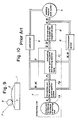
- FIG 10 is a system diagram of the profile working machine.
- a working tool/work system 5 which includes the table 1 and working tool 3, and a load sensor 6 for detecting a force (with force components and moment components applied respectively along and about respective axes) to the working tool 3.
- Designated as letter F are the force components detected by the load sensor 6, while indicated as letter M are the moment components detected by the load sensor 6.
- Numeral 7 indicates a computing unit for control, which is composed of a unit 7A for outputting data on the shape of each working tool (hereinafter called “working tool shape data output unit 7A"), a unit 7B for calculating each working point and tangential plane (hereinafter called “working point/tangential plane calculation unit 7B), and a unit 7C for computing each working point and working reaction force (hereinafter called “working point/working reaction force computing unit 7C).
- the working tool shape data output unit 7A outputs, as a signal, data S on the shape of the working tool 3, for example, a ball having a radius of such and such millimeters or a cylinder having a radius of such and such millimeters and a length of such and such millimeters.
- the working point/tangential plane calculation unit 7B calculates the position of the working point T and the tangential plane P t at the working point T on the basis of the data S output from the working tool shape data output unit 7A and the force F and moment M detected by the load sensor 6.
- the working point/working reaction force computing unit 7C judges, based on the working reaction force F detected by the load sensor 6 and the working point T and tangential plane P t calculated by the working point/tangential plane calculation unit 7B, whether the working reaction force F is suitable or not for the working point T and tangential plane P t , and outputs a position signal X and spatial orientation signal a to correct, if necessary, the working reaction force F.
- Designated as numeral 8 is a drive and control system for respective axes, which operates upon input of the signals X, .
- the drive and control system 8 controls the relative positions X and relative spatial orientations between the table 1 and working tool 3.
- Numeral 9 indicates displacement sensors for detecting the present positions and spatial orientations of the table 1 and working tool 3, and outputs the so-detected position signals X and spatial orientation signals 9.
- the working point T and tangential plane P t are always calculated by the working point/tangential plane calculation unit 7B, and a judgement is made to determine whether the working point T is located at a point where the working tool 3 can perform machining.
- a judgement is made by the working point/working reaction force computing unit 7C to determine whether the present working reaction force F is suitable for the working point T and tangential plane P t .
- the present working reaction force F is suitable, the working is continued as is.
- computation is performed to determine how the relative positions X and relative spatial orientations of the working tool 3 and table 1 should be corrected to adjust the working reaction force F to suitable values.
- the working point/working reaction force computing unit 7C gives commands X, (HJ) to the drive and control system 8 for the respective axes.
- the commands may generally be input in the form of target relative positions X and target relative spatial orientations or in the form of displacements AX, A@ over which the relative positions and relative spatial orientations should be corrected from the present state.
- the above-described profile working machine can perform machining copying the profile, namely, the curved surface of the work 2 while always maintaining the working reaction force exerted on the working tool 3 at the most suitable value. Therefore, the profile working machine allows to conduct profile machining work automatically under ideal working conditions.
- the coordinate system of the working tool 3 is usually different from that of the load sensor 6. No particular correlation is contemplated either between both coordinate systems in the above-described conventional profile working machine. Therefore, the each load component detected by the load sensor is based on the coordinate system of the load sensor 6. In order to determine the working reaction force exerted on the working tool 3, computation is required to transform the value detected by the load sensor 6 into a value under the coordinate system of the working tool 3. Since this computation is complex, the computing unit requires lots of time for its design and fabrication and correspondingly, a rather long period of time is needed to perform the computation.
- the above computation includes a computation step in which the working point T and tangential plane P t are determined.
- This computation is more complex than the above-mentioned computation for the transformation of the coordinate system.
- One example of this computation is described in European Patent Application EP-A-0 177 084. It will be clearly understood from said example how complex the computation is.
- the exemplified computation is limited to a simple example in which the working tool 3 is spherical. Where the working tool 3 has various shapes other than sphere, the computation of the working point T and tangential plane P t will apparently become more complex.
- the computing unit of the working point T and tangential plane P t requires still more manpower and time for its design and fabrication and at the same time, their computation requires substantial time.
- the conventional profile working machine contains, in its control loop, a computation step which requires significant computing time.
- the conventional profile working machine is therefore accompanied by such drawbacks that its computing unit requires a high fabrication cost and since its responsibility, which is needed for the control of forces, is reduced, it cannot achieve any high working speed.
- An object of this invention is to provide a profile working machine which is free of the above-described drawbacks of the prior art and can improve the working speed and responsibility.
- the present invention provides a profile working machine equipped with a support portion for holding a work thereon, a working tool for machining the work and a drive and control system for controlling the relative spatial displacements between the support portion and the working tool and adapted to machine the work into a desired profile, comprising:
- a working reaction force in suitable working conditions has a specific magnitude and direction relative to the tangential plane P t at the working point T on a curved surface to be machined.
- Such working reaction force will hereinafter be called “the suitable working reaction force” for the sake of brevity.
- the actual working reaction force varies depending on working conditions.
- the magnitude of the suitable working reaction force is stored resolved in a load vector value in each of the three directions of a coordinate system fixed on the load sensor.
- a working reaction force is detected in three vector values by the load sensor during the working operation. Each set of detected vector values is compared with the set of vector values stored in the memory unit.
- the suitable working reaction force is set, the set of vector values detected by the load sensor and stored in the memory unit, a set of vector values of an actual working reaction force detected by the load sensor in the course of a working operation is compared with the set of stored vector values, and the relative positions and relative spatial orientations of the table and working tool support mechanism are then controlled on the basis of the deviation of the detected values from the stored values so as to make the detected values equal to the stored values as described above, keeping, relative to the load sensor, the spatial orientation of the actual working reaction force identical to the spatial orientation of the suitable working reaction force. It is therefore possible to omit computing steps substantially, to reduce the cost for the fabrication of the unit required for computation and to increase the working speed and responsibility, so that the working capacity can be improved.
- the expression “the direction is constant relative to the working surface” in case of profile working should read that "the direction is constant relative to the tangential plane for the curved surface, which is to be worked, at the working point as a point of contact between the working tool and work".
- the former expression will be used instead of the latter expression for the sake of simplicity.
- the above description of the empirical fact is now supplemented. If grinding conditions such as material to be ground, working tool, feeding speed and depth of grinding are kept constant, the direction of the actual working reaction force is automatically set as long as the magnitude of the working reaction force is controlled to have the suitable value. In other words, suitable working conditions can be maintained as long as the magnitude of the actual working reaction force is controlled solely.
- the present invention has now materialized a machine capable of performing smooth profile grinding while always maintaining ideal working conditions for a momentarily-changing curved surface.
- FIG. 1 is a system diagram of a profile working machine according to the preferred embodiment of this invention.
- parts of structure similar to their corresponding parts shown in Figure 10 are identified by like reference numerals and their description is omitted.
- Numeral 10 indicates a computing unit for a constant load vector control.
- the computing unit 10 is composed of a memory unit 11, deviation computing unit 12 and displacement computing unit 13.
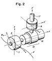
- FIG 2 is a perspective view of the working tool/work system and load sensor, both, illustrated in Figure 1.
- a work 2 fixed on a table and a working tool 3. They are the same as those depicted in Figure 9.
- Designated at numeral 6 is the load sensor shown in Figure 1.
- the load sensor 6 serves to detect force components and moment components along and about the respective axes which extend at right angles.
- a working tool support mechanism 15 for holding and driving the working tool 3
- a coupling member 16 coupling the load sensor 6 and working tool support mechanism 15 together
- a connecting member 17 connecting the unillustrated main body of the working machine and the load sensor 6 to each other.
- the illustrated embodiment is different from the conventional machine in that the conventional machine requires a computing step for the transformation of each coordinate system and another computing step for computing the working point T and tangential plane P t while these computing steps are not needed for the illustrated embodiment of this invention. These differences will next be described with reference to Figure 1 and Figure 2.
- the load sensor 6 detects load components corresponding to the working reaction force F o with respect to the respective x', y' and z' axes.
- load components force components along the x', y' and z' axes will now be identified respectively by F xo ',F yo ' and Fzo' while moment components about the x', y' and z' axes will hereinafter be identified respectively by M XO , Myo and MZO .
- the above force components F xo ,F yo ',F zo and moment components M xo ',M yo ',M zo are first of all stored in the memory unit 11 of the computing unit constant load vector control 10.
- the force components F x ,F y ',F z and moment components F x ,F y ',F z of each actual working reaction force F detected respectively along and about the x', y' and z' axes by the load sensor 6 are compared, at the deviation computing unit 12, respectively with the above-mentioned force components F xo ', F yo ', F zo ' and moment components M xo ',M yo ',M zo ' stored in the memory unit 11, whereby the deviations of the former force and moment components from the latter force and moment components are calculated.
- the respective deviations calculated at the deviation computing unit 12 are then input to the displacement computing unit 13, where based on the thus-input deviations and the present relative positions and relative spatial orientations of the table 1 and working tool support mechanism 15 detected by the displacement sensors 9, computation is performed to determine how much the table 1 and working tool support mechanism 15 should be moved from their present positions and spatial orientations to reduce the deviations to 0.
- Values computed at the displacement computing unit 13 are output to the drive and control system 8 for the respective axes. In accordance with these values, the relative positions and spatial orientations of the table 1 and working tool support mechanism 15 are controlled to reduce the above-described deviations to 0.
- the working reaction force is maintained constant in direction relative to the curved surface under working while maintaining its initial value F o , and at the same time, the direction of the working reaction force and the spatial orientation of the load sensor 6 is always maintained constant in the same relation as the initial relation. In this manner, the profile working operation is performed smoothly.
- the displacement computing unit 13 serves to compute how the relative positions X and relative spatial orientations (the combination of these two vectors will hereinafter be identified by a vector D) between the table 1 and working tool support mechanism 15 should be corrected from their present positions and spatial orientations in order to reduce the deviation of the working reaction force to 0.
- the displacement correcting value AD can be represented by the following linear approximation:
- a determinant expressed in terms of the individual elements of the approximation (1) will next be described as a determinant (2).
- the correcting values ⁇ x , ⁇ y , ⁇ z and the correcting values ⁇ x , ⁇ y , ⁇ z are collectively identified by ⁇ X and ⁇ respectively.
- the values C 11 -C 66 change depending on conditions such as the rigidity of the working machine itself, the rigidity of the work 2 to be worked, the present position and spatial orientation of the working machine, etc. They can be determined when these conditions are specifically indicated.
- control is performed in this embodiment in such a manner that the detected values F x' ,F y' ,F z' ,M x' ,M y' ,M z' remain always equal to their corresponding constant values F xo ',F yo ',F zo ',M xo ',M yo ',M zo '.
- This means that the position and spatial orientation of the load sensor 6 are maintained constant relative to the direction and working point T of the prescribed suitable working reaction force F o .
- the working point T is always maintained at a point satisfying a certain constant positional relation relative to the working tool support mechanism 15, because the relative positional relation between the working tool support mechanism 15 holding the working tool 3 in place thereon and the load sensor 6 is constant. It is therefore possible to avoid the need for the computation of the working point T and hence to omit the computing step for the working point T, so long as control is effected in the above-described manner. It is also unnecessary to compare the actual working reaction force to the prescribed suitable one in the coordinate system of the working tool 3. This eliminates the computation for the transformation of the actual working reaction force detected as values in the coordinate system of the load sensor 6 to those in the coordinate system of the working tool 3, thereby permitting the omission of the computing step for the transformation.
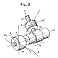
- FIG 3 is a perspective view of a working tool, work and load sensor according to the first specific example of this embodiment.
- parts of structure similar to their corresponding parts shown in Figure 2 are identified by like reference numerals and letters and their description is omitted.
- the relation between the load sensor 6 and the suitable working reaction force F o in this specific example is chosen in such a way that one of the coordinate axes of the load sensor 6 (the z' axis in the illustrated example) extends in parallel with the direction of the working reaction force F o .
- the force components (F xo ', F yo ', F zo ') and moment components (M xo ',M yo ',M zo ') detected by the load sensor 6 upon exertion of the working reaction force F o on the working point T are obviously values conforming the coordinate axes x',y',z' shown in Figure 3. These values are stored in the memory unit 11 of the computing unit for constant load vector control 10.
- the force components (F xo ',F yo ',F zo ') and moment components (M xo ',M yo ',M zo ') detected by the load sensor 6 are compared, at the deviation computing unit 12, axis by axis with their corresponding values stored in the memory unit 11 to compute their differences.
- the so-computed deviations are input to the displacement computing unit 13 to calculate the relative positions and relative spatial orientations of the table 1 and working tool support mechanism 15 for their correction.
- the respective axes are then driven by way of the drive and control system 8 for the respective axes.
- the table 1 and working tool support mechanism 15 are controlled in such a manner that the z' axis of the load sensor 6 is always maintained coincident with the suitable working reaction force F o .
- the force components F xo ',F yo ' and moment components M yo ',M zo ' detected by the load sensor 6 upon exertion of the working reaction force F o are 0 and their corresponding values stored in the memory unit 11 are also 0. Accordingly, the force components Fx',Fy' and moment components MY,MZ detected by the load sensor 6 in the course of the working operation are deviations by themselves. It is thus unnecessary to perform computation with respect to these components at the deviation computing unit 12, thereby simplifying the computation.
- the present embodiment makes it possible to increase the sensitivity with respect to moments about the y' and z' axes so that a significant contribution has been brought about to the control accuracy.
- FIGs 4 and 5 are respectively front and side views of a working and load sensor according to the second specific example of the present embodiment.
- parts of structure similar to their corresponding parts shown in Figure 2 are identified by like reference numerals and letters.
- Numerals 18,18' indicate load sensor support members which are connected respectively to the shaft of the working tool 3 and the coupling member 16 and support the load sensor 6.
- the load sensor 6 and suitable working reaction force F o are chosen in such a relation that one (the z' axis) of the coordinate axes of the load sensor 6 coincides with the direction of the suitable working reaction force F o .
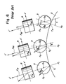
- Figure 6 shows how a working operation making use of the conventional machine proceeds.
- the drawing illustrates the manner of progress of the working operation to positions P 1 ,P 2 ,P 3 in order.
- working points T 1 , T 2 , T 3 at the positions P l ,P 2 ,P 3 and central points 0 1 ,0 2 ,0 3 of the working tool 3 at the positions P l ,P 2 ,P 3 .
- control is performed to maintain the suitable working reaction force F o and its direction ⁇ o (the angle between the normal at the working point T and the direction of the working reaction force F o ) constant relative to the curved surface 2 under the working operation while not changing the spatial orientation of the load sensor 6.
- the angle a between the z'-axis of the load sensor 6 and the normal at the working point T (the angle a is considered to be a parameter representing a relative direction of the tangential plane to the load sensor 6 because the tangential plane is perpendicular to O i T i at the working point T i ) changes.
- Figure 7 shows the manner of working at a certain working position in the course of a working operation which is being performed in the same manner as that depicted in Figure 6. Let's now assume:
- the working reaction force F and its direction ⁇ can be determined for the first time by ascertaining the position of the working point T and the tangential plane (angle a) at the working point T while making use of the detected load information F x ' ' F z ' ' M y ' in their entirety.
- the deviation AF of the working reaction force and the deviation ⁇ of its direction are:
- the conventional machine needs such cumbersome computation as mentioned above to obtain the required deviations even in the simplest case having a degree of freedom with respect to three axes only.
- the complexity of computation apparently increases in a geometric series as the degree of freedom increases one axis by one axis.
- Such computation may itself be performed so long as it is done by those skilled in the art. If it is performed at the control and computing unit 7 of the conventional machine shown in Figure 10, a long computing time is required, the performance of the control is reduced, and the fabrication cost of the computing means increases.
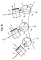
- Figure 8 shows the manner of progress of a working operation in the second specific example. Parts of structure and positions similar to their corresponding parts and positions as depicted in Figure 6 are identified by like reference numerals and letters. As will be understood immediately from the drawing, it is only necessary in this specific example to control the direction ⁇ o of the suitable working reaction force F o and the z'-axis in such a way that they are always coincided with each other.
- the complexity of the computation increases in a geometric series in the conventional machine as the degree of freedom increases.
- the computation is simplified further as the degree of freedom increases.
- the rated moment value is increased in view of the large moments, the rated force value has to be increased correspondingly. Small forces must thus be measured in the large measurement range, leading to a drawback that the control accuracy is reduced considerably. Since all moment components are detected with small values in the present specific example, it is feasible to determine the rated force value in accordance with the magnitudes of forces which occur actually. This improves the control accuracy and at the same time, permits use of a load sensor having a rated capacity smaller compared with the conventional method. The machine can therefore be fabricated at a lower cost.
- the machine of this invention allows to control greater loads with the same load sensor although the conventional machine does not permit application of large forces due to increased moments and the working capacity is considerably limited. Unlike the conventional machine, the machine of this invention permits the control of greater loads by using the same load sensor.
- the present specific example brings about the same effects as the second specific example and at the same time, increases the working capacity compared with the conventional machine equipped with the same load sensor.
- a load sensor having a smaller rated capacity it is feasible to improve the working accuracy and to construct the machine at a lower cost.
- the present embodiment can omit computing steps which have been considered to be indispensable in the conventional machine. It is therefore possible to reduce the fabrication cost for the part required for computation.
- the present embodiment has also brought about such additional effects that the computing speed can be shortened considerably and the responsibility can be improved. It is also possible to retain, without any problems, the characteristic feature that a work can be worked automatically while always maintaining the working reaction force at a suitable value.
- the present embodiment has another a further advantage that it permits use of a load sensor having a smaller rated capacity.
Landscapes
- Engineering & Computer Science (AREA)
- Mechanical Engineering (AREA)
- Computing Systems (AREA)
- Theoretical Computer Science (AREA)
- Human Computer Interaction (AREA)
- Manufacturing & Machinery (AREA)
- Physics & Mathematics (AREA)
- General Physics & Mathematics (AREA)
- Automation & Control Theory (AREA)
- Automatic Control Of Machine Tools (AREA)
- Constituent Portions Of Griding Lathes, Driving, Sensing And Control (AREA)
- Numerical Control (AREA)
- Machine Tool Sensing Apparatuses (AREA)
Description
- This invention relates to a profile working machine such as die-finishing grinding machine, ceramics- working grinding machine, three-dimensional milling machine or the like.
- When performing working or machining to form a free-form curved surface on a work such as die machining, the working or machining is in many instances conducted by mounting a ball end mill or the like on an NC milling machine or a machining center. After such working or machining is performed, cutting tool marks are caused to remain on the thus-finished die. Hence, it cannot be used as a die without any additional machining or treatment. It has thus been required to add a further step in which such cutting tool marks are removed with a shafted grinder held by a hand while observing them. Such a manual work has prevented full automation of machining steps in profile machining work, thereby imposing a serious limitation on the profile machining work.
- With a view toward solving this problem, the present inventors have already proposed in Japanese Patent Application No. 201487/1984 and corresponding European application EP-A-0 177 084, which falls within the Ariticle 54(3) field a profile working machining which permits automated working of curved surfaces of a work. The outline of this profile working machine will next be described with reference to Figures 9 and 10.
- Figure 9 is a side view of a working tool and a work. In the drawing, there are illustrated a table 1 of a working machine, a
work 2 fixedly held on the table 1, and aworking tool 3 for grinding thework 2. Letter T indicates a point of action (working point) by theworking tool 3 on thework 2, while letter F designates a working reaction force exerted on theworking tool 3. - Figure 10 is a system diagram of the profile working machine. In the drawing, there are shown a working tool/
work system 5 which includes the table 1 andworking tool 3, and aload sensor 6 for detecting a force (with force components and moment components applied respectively along and about respective axes) to theworking tool 3. Designated as letter F are the force components detected by theload sensor 6, while indicated as letter M are the moment components detected by theload sensor 6.Numeral 7 indicates a computing unit for control, which is composed of aunit 7A for outputting data on the shape of each working tool (hereinafter called "working tool shapedata output unit 7A"), aunit 7B for calculating each working point and tangential plane (hereinafter called "working point/tangentialplane calculation unit 7B), and aunit 7C for computing each working point and working reaction force (hereinafter called "working point/working reactionforce computing unit 7C). The working tool shapedata output unit 7A outputs, as a signal, data S on the shape of theworking tool 3, for example, a ball having a radius of such and such millimeters or a cylinder having a radius of such and such millimeters and a length of such and such millimeters. The working point/tangentialplane calculation unit 7B calculates the position of the working point T and the tangential plane Pt at the working point T on the basis of the data S output from the working tool shapedata output unit 7A and the force F and moment M detected by theload sensor 6. The working point/working reactionforce computing unit 7C judges, based on the working reaction force F detected by theload sensor 6 and the working point T and tangential plane Pt calculated by the working point/tangentialplane calculation unit 7B, whether the working reaction force F is suitable or not for the working point T and tangential plane Pt, and outputs a position signal X and spatial orientation signal a to correct, if necessary, the working reaction force F. - Designated as
numeral 8 is a drive and control system for respective axes, which operates upon input of the signals X,. In accordance with the signals X, , the drive and
control system 8 controls the relative positions X and relative spatial orientationsbetween the table 1 andworking tool 3.Numeral 9 indicates displacement sensors for detecting the present positions and spatial orientations of the table 1 andworking tool 3, and outputs the so-detected position signals X andspatial orientation signals 9. - In the above construction, the working point T and tangential plane Pt are always calculated by the working point/tangential
plane calculation unit 7B, and a judgement is made to determine whether the working point T is located at a point where theworking tool 3 can perform machining. When the judgement is "YES", a another judgement is made by the working point/working reactionforce computing unit 7C to determine whether the present working reaction force F is suitable for the working point T and tangential plane Pt. When the present working reaction force F is suitable, the working is continued as is. When it is not, computation is performed to determine how the relative positions X and relative spatial orientationsof the
working tool 3 and table 1 should be corrected to adjust the working reaction force F to suitable values. As a result, the working point/working reactionforce computing unit 7C gives commands X, (HJ) to the drive andcontrol system 8 for the respective axes. Here, the commands ,may generally be input in the form of target relative positions X and target relative spatial orientationsor in the form of displacements AX, A@ over which the relative positions and relative spatial orientations should be corrected from the present state. - As mentioned above, the above-described profile working machine can perform machining copying the profile, namely, the curved surface of the
work 2 while always maintaining the working reaction force exerted on theworking tool 3 at the most suitable value. Therefore, the profile working machine allows to conduct profile machining work automatically under ideal working conditions. - In general, the coordinate system of the
working tool 3 is usually different from that of theload sensor 6. No particular correlation is contemplated either between both coordinate systems in the above-described conventional profile working machine. Therefore, the each load component detected by the load sensor is based on the coordinate system of theload sensor 6. In order to determine the working reaction force exerted on theworking tool 3, computation is required to transform the value detected by theload sensor 6 into a value under the coordinate system of theworking tool 3. Since this computation is complex, the computing unit requires lots of time for its design and fabrication and correspondingly, a rather long period of time is needed to perform the computation. - The above computation includes a computation step in which the working point T and tangential plane Pt are determined. This computation is more complex than the above-mentioned computation for the transformation of the coordinate system. One example of this computation is described in European Patent Application EP-A-0 177 084. It will be clearly understood from said example how complex the computation is. Moreover, the exemplified computation is limited to a simple example in which the
working tool 3 is spherical. Where theworking tool 3 has various shapes other than sphere, the computation of the working point T and tangential plane Pt will apparently become more complex. Correspondingly, the computing unit of the working point T and tangential plane Pt requires still more manpower and time for its design and fabrication and at the same time, their computation requires substantial time. - As has been described above, the conventional profile working machine contains, in its control loop, a computation step which requires significant computing time. The conventional profile working machine is therefore accompanied by such drawbacks that its computing unit requires a high fabrication cost and since its responsibility, which is needed for the control of forces, is reduced, it cannot achieve any high working speed.
- An object of this invention is to provide a profile working machine which is free of the above-described drawbacks of the prior art and can improve the working speed and responsibility.
- In order to achieve the above-described object of this invention, the present invention provides a profile working machine equipped with a support portion for holding a work thereon, a working tool for machining the work and a drive and control system for controlling the relative spatial displacements between the support portion and the working tool and adapted to machine the work into a desired profile, comprising:
- a displacement sensor for detecting the present relative spatial displacements between the support portion and the working tool;
- a load sensor for detecting the working reaction force exerted on the working tool along each of the axes of a coordinate system based on the load sensor;
- a memory unit for storing the magnitude of the force detected by the load sensor along each of the axes of the coordinate system while a predetermined suitable working reaction force is being exerted on the working tool;
- a deviation computing unit for computing the deviation between the detected and stored forces along each of the axes; and
- a displacement computing unit for computing on the basis of the outputs of the displacement sensor and deviation computing unit, the relative displacements required to bring the deviations along each axis to zero and to maintain in the course of a working operation the spatial orientation of the load sensor relative to the direction of the suitable working reaction force constant.
- A working reaction force in suitable working conditions has a specific magnitude and direction relative to the tangential plane Pt at the working point T on a curved surface to be machined. Such working reaction force will hereinafter be called "the suitable working reaction force" for the sake of brevity. The actual working reaction force varies depending on working conditions. In the memory unit, the magnitude of the suitable working reaction force is stored resolved in a load vector value in each of the three directions of a coordinate system fixed on the load sensor. In an actual working operation, a working reaction force is detected in three vector values by the load sensor during the working operation. Each set of detected vector values is compared with the set of vector values stored in the memory unit. Based on the differences of the detected set and the stored set as well as the present relative positions and spatial orientations between the work support portion and working portion detected by the displacement sensors, computation is performed by the displacement computing unit to determine the required displacements between the work support portion and working portion to reduce the differences between the stored and the detected set to 0. When the drive and control system is controlled in accordance with the relative displacements, the direction of the above-mentioned working reaction force is maintained unaltered relative to the spatial orientation of the load sensor. As a result, the reasonability of the control algorithm of the present system is assured and at the same time, smooth and automatic grinding of a curved surface is materialized.
- In the present invention, the suitable working reaction force is set, the set of vector values detected by the load sensor and stored in the memory unit, a set of vector values of an actual working reaction force detected by the load sensor in the course of a working operation is compared with the set of stored vector values, and the relative positions and relative spatial orientations of the table and working tool support mechanism are then controlled on the basis of the deviation of the detected values from the stored values so as to make the detected values equal to the stored values as described above, keeping, relative to the load sensor, the spatial orientation of the actual working reaction force identical to the spatial orientation of the suitable working reaction force. It is therefore possible to omit computing steps substantially, to reduce the cost for the fabrication of the unit required for computation and to increase the working speed and responsibility, so that the working capacity can be improved.
- The above and other objects, features and advantages of the present invention will become apparent from the following description and the appended claims, taken in conjunction with the accompanying drawings, in which:
- Figure 1 is a system diagram of a profile working machine according to one embodiment of this invention;
- Figure 2 is a perspective view of a working tool/work system and load sensor depicted in Figure 1;
- Figure 3 is a perspective view of a working tool/work system and load sensor according to the first specific example of the embodiment;
- Figures 4 and 5 are front and side views of a working tool/work system and load sensor according to the second specific example of the embodiment;
- Figures 6 and 7 illustrate the progress of a working operation by a conventional machine and the manner of working of the operation;
- Figure 8 illustrates the progress of a working operation in the second example of the embodiment;
- Figure 9 is a side view of a working tool and work; and
- Figure 10 is a system diagram of a conventional profile working machine.
- Prior to description of a preferred embodiment of this invention, a description will be made of certain facts revealed as a result of investigations of the present inventors. According to Norio Takenaka, Takaaki Nagao, et al. "A Study on the Face Grinding by Using A Single Grain (First Report)" described in "SEIMITSU KIKAI (Journal of the Japan Society of Precision Engineering)", 45(9), 1113; and "Erforschung des Mechanismus beim Stirnschleifen" described in "Werkstatt und Betrieb", 112(9), 655 (1979), it is indicated that once grinding conditions such as material to be ground, working tool, feeding speed and depth of grinding are set, the magnitude of the working reaction force and its direction relative to the working surface take substantially constant values. Strictly speaking the expression "the direction is constant relative to the working surface" in case of profile working should read that "the direction is constant relative to the tangential plane for the curved surface, which is to be worked, at the working point as a point of contact between the working tool and work". Although the present invention is directed to profile working, the former expression will be used instead of the latter expression for the sake of simplicity. The above description of the empirical fact is now supplemented. If grinding conditions such as material to be ground, working tool, feeding speed and depth of grinding are kept constant, the direction of the actual working reaction force is automatically set as long as the magnitude of the working reaction force is controlled to have the suitable value. In other words, suitable working conditions can be maintained as long as the magnitude of the actual working reaction force is controlled solely.
- It was necessary to determine the direction of an actual working reaction force and a working point and tangential plane in the prior art although the magnitude of the actual reaction force can be detected by a load sensor, because such pieces of information were indispensable to judge how the drive and control system for the respective axes should be controlled to correct the magnitude of the actual working reaction force to its suitable value. If the position of the working point, in other words, the working point of the actual working reaction force is known relative to the load sensor, it is only necessary to determine the magnitude of the actual working reaction force to enable the above mentioned controls. It is only true on the assumption that a working tool is usually circular in its cross-section and the worked surface is in contact with the working tool at the working point. This assumption is reasonable in most cases.
- Owing to the provision of the above-described means which act as mentioned above, the present invention has now materialized a machine capable of performing smooth profile grinding while always maintaining ideal working conditions for a momentarily-changing curved surface.
- The present invention will hereinafter be described on the basis of the illustrated embodiment.
- Figure 1 is a system diagram of a profile working machine according to the preferred embodiment of this invention. In the drawing, parts of structure similar to their corresponding parts shown in Figure 10 are identified by like reference numerals and their description is omitted.
Numeral 10 indicates a computing unit for a constant load vector control. Thecomputing unit 10 is composed of a memory unit 11,deviation computing unit 12 anddisplacement computing unit 13. - Figure 2 is a perspective view of the working tool/work system and load sensor, both, illustrated in Figure 1. In the drawing, there are shown a
work 2 fixed on a table and a workingtool 3. They are the same as those depicted in Figure 9. Designated atnumeral 6 is the load sensor shown in Figure 1. Theload sensor 6 serves to detect force components and moment components along and about the respective axes which extend at right angles. There are also illustrated a workingtool support mechanism 15 for holding and driving the workingtool 3, acoupling member 16 coupling theload sensor 6 and workingtool support mechanism 15 together, and a connectingmember 17 connecting the unillustrated main body of the working machine and theload sensor 6 to each other. - The illustrated embodiment is different from the conventional machine in that the conventional machine requires a computing step for the transformation of each coordinate system and another computing step for computing the working point T and tangential plane Pt while these computing steps are not needed for the illustrated embodiment of this invention. These differences will next be described with reference to Figure 1 and Figure 2.
- In Figure 2, letters x,y,z indicate the coordinate axes of the working
tool 3 whereas letters x',y',z' designate the coordinate axes of theload sensor 6. Once the shape of the workingtool 3, the material of thework 2 and various other working conditions are set, the suitable working reaction force exerted to the working point T during the working operation is determined, as mentioned above, as values having a specific magnitude and direction relative to the curved surface which is being worked. The suitable working reaction force will hereinafter be identified by "Fo". This suitable working reaction force Fo is shown as a vector in Figure 2. The suitable working reaction force Fo is exerted on the working point T between the working tool and work while a suitable working operation is being performed. Then, theload sensor 6 detects load components corresponding to the working reaction force Fowith respect to the respective x', y' and z' axes. Among these load components, force components along the x', y' and z' axes will now be identified respectively by Fxo',Fyo' and Fzo' while moment components about the x', y' and z' axes will hereinafter be identified respectively by MXO , Myo and MZO . - As a general rule, in order to work a curved surface suitably, it is necessary and sufficient conditions to control the working reaction force exerted on the working point T in such a manner that the working reaction force is always maintained equal to the above-described suitable working reaction force Fo having a specific magnitude and direction relative to the curved surface under working. For this purpose, the above force components Fxo,Fyo',Fzo and moment components Mxo',Myo',Mzo are first of all stored in the memory unit 11 of the computing unit constant
load vector control 10. During the working operation, the force components Fx,Fy',Fz and moment components Fx,Fy',Fz of each actual working reaction force F detected respectively along and about the x', y' and z' axes by theload sensor 6 are compared, at thedeviation computing unit 12, respectively with the above-mentioned force components Fxo', Fyo', Fzo' and moment components Mxo',Myo',Mzo' stored in the memory unit 11, whereby the deviations of the former force and moment components from the latter force and moment components are calculated. - The respective deviations calculated at the
deviation computing unit 12 are then input to thedisplacement computing unit 13, where based on the thus-input deviations and the present relative positions and relative spatial orientations of the table 1 and workingtool support mechanism 15 detected by thedisplacement sensors 9, computation is performed to determine how much the table 1 and workingtool support mechanism 15 should be moved from their present positions and spatial orientations to reduce the deviations to 0. Values computed at thedisplacement computing unit 13 are output to the drive andcontrol system 8 for the respective axes. In accordance with these values, the relative positions and spatial orientations of the table 1 and workingtool support mechanism 15 are controlled to reduce the above-described deviations to 0. - As a result, the working reaction force is maintained constant in direction relative to the curved surface under working while maintaining its initial value Fo, and at the same time, the direction of the working reaction force and the spatial orientation of the
load sensor 6 is always maintained constant in the same relation as the initial relation. In this manner, the profile working operation is performed smoothly. - Here, a brief description is made of the computation by the
displacement computing unit 13 in the course of the above operation. As mentioned above, thedisplacement computing unit 13 serves to compute how the relative positions X and relative spatial orientations(the combination of these two vectors will hereinafter be identified by a vector D) between the table 1 and workingtool support mechanism 15 should be corrected from their present positions and spatial orientations in order to reduce the deviation of the working reaction force to 0. The displacement correcting value AD can be represented by the following linear approximation:
- ΔL: vector as a combination of the deviations △F and △M computed by the
deviation computing unit 12; and - C: constant.
- In order to explain the significance of the approximation (1), a determinant expressed in terms of the individual elements of the approximation (1) will next be described as a determinant (2). It should be borne in mind that in Figure 1, the correcting values Δx,Δy,Δz and the correcting values Δθx,Δθy,Δθz are collectively identified by ΔX and Δrespectively.

work 2 to be worked, the present position and spatial orientation of the working machine, etc. They can be determined when these conditions are specifically indicated. - At the
displacement computing unit 13, computation is performed in accordance with the determinant (2). Once the deviation ΔL is obtained, the correcting value AD for the relative positions and spatial orientations can be determined. As a result, it is possible to maintain the relative positions and relative spatial orientations between the table 1 and workingtool support mechanism 15 always in the prescribed state. - As mentioned above, control is performed in this embodiment in such a manner that the detected values Fx',Fy',Fz',Mx',My',Mz' remain always equal to their corresponding constant values Fxo',Fyo',Fzo',Mxo',Myo',Mzo'. This means that the position and spatial orientation of the
load sensor 6 are maintained constant relative to the direction and working point T of the prescribed suitable working reaction force Fo. It also means that the working point T is always maintained at a point satisfying a certain constant positional relation relative to the workingtool support mechanism 15, because the relative positional relation between the workingtool support mechanism 15 holding the workingtool 3 in place thereon and theload sensor 6 is constant. It is therefore possible to avoid the need for the computation of the working point T and hence to omit the computing step for the working point T, so long as control is effected in the above-described manner. It is also unnecessary to compare the actual working reaction force to the prescribed suitable one in the coordinate system of the workingtool 3. This eliminates the computation for the transformation of the actual working reaction force detected as values in the coordinate system of theload sensor 6 to those in the coordinate system of the workingtool 3, thereby permitting the omission of the computing step for the transformation. - Advantages which have been brought about from the omission of these computing steps can be clearly understood, if a description is made of actual computation performed in the conventional working machine. It is however too complex to explain this computation on a general example. It will therefore be described in the second specific example which is a special example of the present embodiment and will be described later in this specification.
- The embodiment of this invention has been described above. The description of the above embodiment has been made on a general example in which the positions and spatial orientations of the
load sensor 6 and the suitable working reaction force Fo are in an arbitrary relation. If the positional relation between theload sensor 6 and the suitable working reaction force Fo is chosen to meet a certain specific relation, other meritorious features can be brought about in addition to the advantage that the computing steps can be omitted. Another description will next be made of two specific examples in which the positional relation between theload sensor 6 and the suitable working reaction force Fo is chosen to meet a certain specific relation. - Figure 3 is a perspective view of a working tool, work and load sensor according to the first specific example of this embodiment. In the drawing, parts of structure similar to their corresponding parts shown in Figure 2 are identified by like reference numerals and letters and their description is omitted. As apparent from the drawing, the relation between the
load sensor 6 and the suitable working reaction force Fo in this specific example is chosen in such a way that one of the coordinate axes of the load sensor 6 (the z' axis in the illustrated example) extends in parallel with the direction of the working reaction force Fo. - When the positional relation between the
load sensor 6 and the working reaction force Fo is set in the above-described manner, the force components (Fxo', Fyo', Fzo') and moment components (Mxo',Myo',Mzo') detected by theload sensor 6 upon exertion of the working reaction force Fo on the working point T are obviously values conforming the coordinate axes x',y',z' shown in Figure 3. These values are stored in the memory unit 11 of the computing unit for constantload vector control 10. During the working operation, the force components (Fxo',Fyo',Fzo') and moment components (Mxo',Myo',Mzo') detected by theload sensor 6 are compared, at thedeviation computing unit 12, axis by axis with their corresponding values stored in the memory unit 11 to compute their differences. The so-computed deviations are input to thedisplacement computing unit 13 to calculate the relative positions and relative spatial orientations of the table 1 and workingtool support mechanism 15 for their correction. The respective axes are then driven by way of the drive andcontrol system 8 for the respective axes. As a result, the table 1 and workingtool support mechanism 15 are controlled in such a manner that the z' axis of theload sensor 6 is always maintained coincident with the suitable working reaction force Fo. - Since the z' axis of the
load sensor 6 and the direction of the suitable working reaction force Fo are parallel to each other in this specific example, the force components Fxo',Fyo' and moment components Myo',Mzo' detected by theload sensor 6 upon exertion of the working reaction force Fo are 0 and their corresponding values stored in the memory unit 11 are also 0. Accordingly, the force components Fx',Fy' and moment components MY,MZ detected by theload sensor 6 in the course of the working operation are deviations by themselves. It is thus unnecessary to perform computation with respect to these components at thedeviation computing unit 12, thereby simplifying the computation. - So long as the above control mode is running without any problems, values detected on these components become extremely small compared with values detected with respect to the other components. It is hence possible to lower the rated capacities of the
load sensor 6 for these components, and as a result, to increase the sensitivity to these components. For these reasons, the accuracy of the overall control is increased significantly. In general, the rated capacities of the moment components are limited above larger levels because they are products of the suitable working reaction force Fo and the distances from the working point T to a point determined corresponding to the center of the coordinate system of theload sensor 6. Due to such larger rated capacities, it may not be possible to achieve sufficiently high sensitivity in some instances. Unlike the above-mentioned situation, the present embodiment makes it possible to increase the sensitivity with respect to moments about the y' and z' axes so that a significant contribution has been brought about to the control accuracy. - Since a coordinate system has been set to make one of the axes of the load sensor and the direction of the suitable working reaction force parallel to each other in the present specific example, it is possible not only to omit the computing steps but also to improve the sensitivity of the load sensor with respect to components along and around a desired axis. As a consequence, the overall control accuracy can be improved.
- Figures 4 and 5 are respectively front and side views of a working and load sensor according to the second specific example of the present embodiment. In the drawings, parts of structure similar to their corresponding parts shown in Figure 2 are identified by like reference numerals and letters.
Numerals 18,18' indicate load sensor support members which are connected respectively to the shaft of the workingtool 3 and thecoupling member 16 and support theload sensor 6. As apparent from the drawings, in the present specific example, theload sensor 6 and suitable working reaction force Fo are chosen in such a relation that one (the z' axis) of the coordinate axes of theload sensor 6 coincides with the direction of the suitable working reaction force Fo. - In order to clarify the significant advantages of the present embodiment over the conventional machine, a description will next be made, with reference to Figures 6 and 7, of computation by the conventional machine in a simple example of the working reaction force being in the x'-z' plane, namely having only 3 degrees of freedom of force components along x', y' axes and a moment component about y' axis. In these drawings, parts of structure similar to their corresponding parts shown in Figure 2 are identified by like reference numerals and letters.
- Figure 6 shows how a working operation making use of the conventional machine proceeds. The drawing illustrates the manner of progress of the working operation to positions P1 ,P2,P3 in order. There are shown working points T1, T2, T3 at the positions Pl,P2,P3 and central points 01,02,03 of the working
tool 3 at the positions Pl,P2,P3. As one of typical working methods making use of the conventional machine, it may be mentioned a method in which so long as the workingtool 3 can machine thework 2, the working operation is continued while maintaining the spatial orientations of theload sensor 6 and workingtool support mechanism 15 as they are. Namely, as illustrated in the drawing, control is performed to maintain the suitable working reaction force Fo and its direction Φo (the angle between the normal at the working point T and the direction of the working reaction force Fo) constant relative to thecurved surface 2 under the working operation while not changing the spatial orientation of theload sensor 6. However, as the working operation advances from the position P1 to the positions P2,P3, the angle a between the z'-axis of theload sensor 6 and the normal at the working point T (the angle a is considered to be a parameter representing a relative direction of the tangential plane to theload sensor 6 because the tangential plane is perpendicular toOiTi at the working point Ti) changes. As a result, the force components Fx',Fz' and moment component My detected by theload sensor 6 also vary as shown in the drawing (the illustration of My is omitted). Let's thus determine the relation between the values Fx',Fz', My detected by theload sensor 6 and the actual working reaction force F, its direction Φ and the angle a. - Figure 7 shows the manner of working at a certain working position in the course of a working operation which is being performed in the same manner as that depicted in Figure 6. Let's now assume:
- L: the distance between the center O of the working
tool 3 and the origin 0' of the coordinate system of theload sensor 6; - r: the radius of the working
tool 3; and - s: the distance between the origin O' of the coordinate system of the
load sensor 6 and a crossing point H of an extension of the working reaction force F and a perpendicular drawn from the origin O' to the extension. - Since the working reaction force and the detected composite force F' are parallel to each other,


- On the other hand, the moment component My which is to be detected is represented as follow:

- Here, the distance s is:

- Accordingly,

- From the equations (3) and (4), the working reaction force F and its direction Φ are expressed as follows:


- However, the direction Φ of the working reaction force F is still unknown unless the angle a is known in the equation (9). In other words, the direction Φ of the working reaction force is not known so long as the working point T and the tangential plane at the working point T are unknown. It is thus necessary to determine the angle a by using the moment information My in the equation (7). Namely, from the equation (3),

- Inserting the equation (10) into the equation (7),


- In the above-described manner, the working reaction force F and its direction Φ can be determined for the first time by ascertaining the position of the working point T and the tangential plane (angle a) at the working point T while making use of the detected load information Fx''Fz''My' in their entirety.
- It is then necessary to compare the so-determined working reaction force F and its direction Φ with the suitable working reaction force Fo and its direction Φo so that their deviations are determined. Namely, the deviation AF of the working reaction force and the deviation ΔΦ of its direction are:


- From the equations (3), (4) and (11), the following equations can be derived to determine how much the values Fx',Fz',My' change respectively when F and Φ vary by AF and ΔΦ respectively.


- By inserting the values, which have been determined in the equations (13) and (14), in the values AF and ΔΦ in these equations (15), (16) and (17), it is for the first time possible to obtain the intended deviations, namely, the deviations required for controlling the working reaction force and its direction in such a way that they coincide respectively with the values Fo and Φo.
- The conventional machine needs such cumbersome computation as mentioned above to obtain the required deviations even in the simplest case having a degree of freedom with respect to three axes only. The complexity of computation apparently increases in a geometric series as the degree of freedom increases one axis by one axis. Such computation may itself be performed so long as it is done by those skilled in the art. If it is performed at the control and
computing unit 7 of the conventional machine shown in Figure 10, a long computing time is required, the performance of the control is reduced, and the fabrication cost of the computing means increases. - In the second specific example having the same degree of freedom of 3, deviation signals can however be obtained with extreme ease in the following manner without need for such complex computation as that required in the conventional machine. Namely, Figure 8 shows the manner of progress of a working operation in the second specific example. Parts of structure and positions similar to their corresponding parts and positions as depicted in Figure 6 are identified by like reference numerals and letters. As will be understood immediately from the drawing, it is only necessary in this specific example to control the direction Φo of the suitable working reaction force Fo and the z'-axis in such a way that they are always coincided with each other. It is hence necessary to perform the control in such a way that the force component Fz detected by the
load sensor 6 becomes the working reaction force Fo and both force component Fx' and moment component My become 0. The values Fx',My' detected by theload sensor 6 are therefore obtained directly as deviations ΔFx',ΔMy' . Consequently, the computation by the computing unit for constantload vector control 10, which is shown in Figure 1, becomes only the subtraction of (F,, - Fo) in the second specific example. It is thus clear that the time required for the computation is significantly shortened compared with the conventional machine. - As mentioned above, the complexity of the computation increases in a geometric series in the conventional machine as the degree of freedom increases. In the present embodiment, it is only necessary to perform six subtractions even if the degree of freedom is 6. Compared with the conventional machine, the computation is simplified further as the degree of freedom increases.
- Computation by the conventional machine has been described above to show that the present specific example can leapingly shorten the computing time in comparison with the conventional machine. The specific example has other advantages. In the present specific example, as mentioned in the description of the first specific example, detected values of the components other than the force component along the z'- axis become extremely small. It is thus possible to increase the sensitivity to such components and to increase the control accuracy significantly with respect to the components. In a load sensor, there is generally a specific relation between the rated capacity of its force and the rated capacity of its moment. It is thus impossible to set only one of the rated capacities at a large level irrespective of the other one. According to the conventional method, the working points of forces are remote from the load sensor. Large moments are therefore applied to the load sensor. If the rated moment value is increased in view of the large moments, the rated force value has to be increased correspondingly. Small forces must thus be measured in the large measurement range, leading to a drawback that the control accuracy is reduced considerably. Since all moment components are detected with small values in the present specific example, it is feasible to determine the rated force value in accordance with the magnitudes of forces which occur actually. This improves the control accuracy and at the same time, permits use of a load sensor having a rated capacity smaller compared with the conventional method. The machine can therefore be fabricated at a lower cost. If a load sensor having the same rated capacity as the conventional machine is used, the machine of this invention allows to control greater loads with the same load sensor although the conventional machine does not permit application of large forces due to increased moments and the working capacity is considerably limited. Unlike the conventional machine, the machine of this invention permits the control of greater loads by using the same load sensor.
- Since one of the axes of the load sensor and the direction of the suitable working reaction force are set to coincide with each other in this specific example as mentioned above, the present specific example brings about the same effects as the second specific example and at the same time, increases the working capacity compared with the conventional machine equipped with the same load sensor. By using a load sensor having a smaller rated capacity, it is feasible to improve the working accuracy and to construct the machine at a lower cost.
- One general example of the embodiment and its specific examples have been described above. As a matter of fact, the present embodiment can omit computing steps which have been considered to be indispensable in the conventional machine. It is therefore possible to reduce the fabrication cost for the part required for computation. The present embodiment has also brought about such additional effects that the computing speed can be shortened considerably and the responsibility can be improved. It is also possible to retain, without any problems, the characteristic feature that a work can be worked automatically while always maintaining the working reaction force at a suitable value. When one of the coordinate axes of the load sensor and the direction of the prescribed suitable working reaction force are brought into a specific correlation, it is possible to increase the working capacity or to increase the detection sensitivity of the load sensor so as to improve the control accuracy. Besides, the present embodiment has another a further advantage that it permits use of a load sensor having a smaller rated capacity.
In the above linear approximation (1), △D indicates position-correcting values △x,△y,△z along the respective axes and spatial orientation correcting values △θx,△θy,△θz about the respective axes. On the other hand, AL indicates deviations △Fx,△Fy,△Fz of the force components along the respective axes and deviations ΔMx,ΔMy,ΔMz of the moment components about the respective axes. Namely, AD and ΔL are six- dimensional vectors respectively.
Here, the angle between the perpendicular drawn from the origin O to a line segment O'-H and the z'-axis becomes (Φ - a).
Claims (3)
Applications Claiming Priority (2)
| Application Number | Priority Date | Filing Date | Title |
|---|---|---|---|
| JP44165/86 | 1986-03-03 | ||
| JP61044165A JPH074765B2 (en) | 1986-03-03 | 1986-03-03 | Curved surface processing equipment |
Publications (3)
| Publication Number | Publication Date |
|---|---|
| EP0240048A2 EP0240048A2 (en) | 1987-10-07 |
| EP0240048A3 EP0240048A3 (en) | 1989-03-29 |
| EP0240048B1 true EP0240048B1 (en) | 1994-06-15 |
Family
ID=12683977
Family Applications (1)
| Application Number | Title | Priority Date | Filing Date |
|---|---|---|---|
| EP87200375A Expired - Lifetime EP0240048B1 (en) | 1986-03-03 | 1987-03-02 | Profile working machine |
Country Status (4)
| Country | Link |
|---|---|
| US (1) | US4772161A (en) |
| EP (1) | EP0240048B1 (en) |
| JP (1) | JPH074765B2 (en) |
| DE (1) | DE3750050T2 (en) |
Families Citing this family (20)
| Publication number | Priority date | Publication date | Assignee | Title |
|---|---|---|---|---|
| US5157878A (en) * | 1987-03-19 | 1992-10-27 | Canon Kabushiki Kaisha | Polishing method with error correction |
| JP2977203B2 (en) * | 1989-04-19 | 1999-11-15 | 株式会社東芝 | Polishing equipment |
| DE69028041T2 (en) * | 1989-05-17 | 1997-01-09 | Fujitsu Ltd | Profile control system for robots |
| US6205371B1 (en) * | 1990-08-11 | 2001-03-20 | Dieter Wolter-Doll | Method and apparatus for detecting machining flaws, especially caused by grinding machines |
| JP2838014B2 (en) * | 1993-03-31 | 1998-12-16 | マツダ株式会社 | Polishing equipment |
| JP3497031B2 (en) * | 1995-03-07 | 2004-02-16 | 日立建機株式会社 | Hydraulic pump control device |
| US5788435A (en) * | 1995-04-28 | 1998-08-04 | Mccarthy; John F. | Automated diamond cutter apparatus |
| JPH0997112A (en) * | 1995-09-28 | 1997-04-08 | Toyota Motor Corp | Trajectory control method and device |
| KR100225422B1 (en) * | 1995-12-19 | 1999-10-15 | 세구치 류이치 | Method of output correction for control apparatus, the control apparatus, and hydraulic pump control apparatus |
| US6934616B2 (en) * | 2002-12-17 | 2005-08-23 | Caterpillar Inc | System for determining an implement arm position |
| JP4435526B2 (en) * | 2003-09-19 | 2010-03-17 | 独立行政法人理化学研究所 | Free curved surface precision machining tool |
| DE102004003203A1 (en) * | 2004-01-22 | 2005-08-11 | Robert Bosch Gmbh | Electric hand tool with optimized working area |
| US20070033785A1 (en) * | 2005-08-09 | 2007-02-15 | Kohring Mark D | Ridge vent with biocidal source |
| JP5260139B2 (en) * | 2008-05-22 | 2013-08-14 | 株式会社日進製作所 | Grinding wheel contact sensing method and apparatus, honing method and honing machine |
| US8550876B2 (en) * | 2011-08-08 | 2013-10-08 | Apple Inc. | Force-controlled surface finishing through the use of a passive magnetic constant-force device |
| WO2021009903A1 (en) | 2019-07-18 | 2021-01-21 | 株式会社安川電機 | Robot system, robot control method, and servo system |
| JP7222427B2 (en) | 2019-07-18 | 2023-02-15 | 株式会社安川電機 | Control system, control device and control method |
| CN114616076B (en) * | 2019-11-27 | 2024-07-19 | 株式会社安川电机 | Grinding system, correction amount estimation device, storage medium and grinding method |
| CN112720060B (en) * | 2020-12-18 | 2022-08-05 | 湖北三江航天红阳机电有限公司 | Double-profile curved surface narrow and long duct part machining reference determination method |
| CN118357784B (en) * | 2024-04-24 | 2024-10-15 | 力鼎智能装备(青岛)集团有限公司 | Processing equipment operation monitored control system based on artificial intelligence |
Family Cites Families (12)
| Publication number | Priority date | Publication date | Assignee | Title |
|---|---|---|---|---|
| US3548172A (en) * | 1964-08-24 | 1970-12-15 | Bendix Corp | Adaptive control system for numerically controlled machine tool |
| CH486289A (en) * | 1968-08-08 | 1970-02-28 | Kistler Instrumente Ag | Electrical monitoring system for machine tools |
| JPS5114745B1 (en) * | 1970-03-24 | 1976-05-12 | ||
| US3665493A (en) * | 1970-03-30 | 1972-05-23 | Bendix Corp | Adaptive numerical control system for a machine tool |
| JPS4849088A (en) * | 1971-10-22 | 1973-07-11 | ||
| IT1078641B (en) * | 1976-09-14 | 1985-05-08 | Olivetti & Co Spa | IMPROVEMENTS AT A SELF-ADAPTIVE MACHINING CENTER FOR PROGRAMMABLE AUTOMATION |
| SU709325A1 (en) * | 1977-12-19 | 1980-01-15 | Ордена Трудового Красного Знамени Экспериментальный Научно-Исследовательский Институт Металлорежущих Станков | Cutting process automatic monitoring apparatus |
| JPS5754054A (en) * | 1980-09-11 | 1982-03-31 | Toyoda Mach Works Ltd | Tool correcting apparatus provided with contact detector |
| JPS5834746A (en) * | 1981-08-20 | 1983-03-01 | Toshiba Mach Co Ltd | Control apparatus for roll grinding machine |
| JPS5973272A (en) * | 1982-10-18 | 1984-04-25 | Inoue Japax Res Inc | Numerical controlled polishing device |
| US4523409A (en) * | 1983-05-19 | 1985-06-18 | The Charles Stark Draper Laboratory, Inc. | Automatic contour grinding system |
| JPS6179549A (en) * | 1984-09-28 | 1986-04-23 | Takaaki Nagao | Curved surface working device |
-
1986
- 1986-03-03 JP JP61044165A patent/JPH074765B2/en not_active Expired - Lifetime
-
1987
- 1987-02-27 US US07/020,123 patent/US4772161A/en not_active Expired - Fee Related
- 1987-03-02 EP EP87200375A patent/EP0240048B1/en not_active Expired - Lifetime
- 1987-03-02 DE DE3750050T patent/DE3750050T2/en not_active Expired - Fee Related
Also Published As
| Publication number | Publication date |
|---|---|
| EP0240048A3 (en) | 1989-03-29 |
| US4772161A (en) | 1988-09-20 |
| DE3750050T2 (en) | 1994-12-15 |
| JPS62203756A (en) | 1987-09-08 |
| JPH074765B2 (en) | 1995-01-25 |
| DE3750050D1 (en) | 1994-07-21 |
| EP0240048A2 (en) | 1987-10-07 |
Similar Documents
| Publication | Publication Date | Title |
|---|---|---|
| EP0240048B1 (en) | Profile working machine | |
| US4906907A (en) | Robot system | |
| US5509847A (en) | Control robot | |
| US5711697A (en) | Robot control system | |
| CN107498388B (en) | Rotation center correcting device for yaw head | |
| US5920169A (en) | Servomotor control method | |
| US5765976A (en) | Method of controlling the normal direction of the main shaft of the numerical control machine tool | |
| US12377507B2 (en) | Control device, industrial machine, and control method | |
| JPH07205022A (en) | Whetstone wear correction method for force control robot | |
| EP0364593B1 (en) | Machine tool having two main spindles | |
| US5479353A (en) | System for correcting tool deformation amount | |
| US20180203429A1 (en) | Controller | |
| JPH05116081A (en) | Weight and center of gravity position correcting device for force control working machine | |
| JP3119308B2 (en) | Machining center | |
| TWI638250B (en) | Position controller for controlling a rotation center of a tilting head | |
| JPH05318283A (en) | Tool deflection correcting system | |
| JPH052455B2 (en) | ||
| JP2980933B2 (en) | Impact test piece automatic processing system and impact test piece automatic processing method | |
| JPH03149171A (en) | Tool locus control device for industrial robot | |
| JP2508719B2 (en) | Position correction method for automatic grinding machine and its apparatus | |
| JPH0357422Y2 (en) | ||
| JPS61230841A (en) | How to correct tool trajectory for numerically controlled machine tools | |
| JP2920677B2 (en) | Wear compensation method for worn tools | |
| JPH07110470B2 (en) | Workpiece mounting error correction device in machining center | |
| KR0183675B1 (en) | Position controlling method of robot |
Legal Events
| Date | Code | Title | Description |
|---|---|---|---|
| PUAI | Public reference made under article 153(3) epc to a published international application that has entered the european phase |
Free format text: ORIGINAL CODE: 0009012 |
|
| AK | Designated contracting states |
Kind code of ref document: A2 Designated state(s): DE FR GB NL SE |
|
| PUAL | Search report despatched |
Free format text: ORIGINAL CODE: 0009013 |
|
| AK | Designated contracting states |
Kind code of ref document: A3 Designated state(s): DE FR GB NL SE |
|
| 17P | Request for examination filed |
Effective date: 19890816 |
|
| 17Q | First examination report despatched |
Effective date: 19910820 |
|
| GRAA | (expected) grant |
Free format text: ORIGINAL CODE: 0009210 |
|
| AK | Designated contracting states |
Kind code of ref document: B1 Designated state(s): DE FR GB NL SE |
|
| PG25 | Lapsed in a contracting state [announced via postgrant information from national office to epo] |
Ref country code: FR Free format text: THE PATENT HAS BEEN ANNULLED BY A DECISION OF A NATIONAL AUTHORITY Effective date: 19940615 |
|
| REF | Corresponds to: |
Ref document number: 3750050 Country of ref document: DE Date of ref document: 19940721 |
|
| ET | Fr: translation filed | ||
| EAL | Se: european patent in force in sweden |
Ref document number: 87200375.1 |
|
| PG25 | Lapsed in a contracting state [announced via postgrant information from national office to epo] |
Ref country code: GB Effective date: 19950302 |
|
| PG25 | Lapsed in a contracting state [announced via postgrant information from national office to epo] |
Ref country code: SE Effective date: 19950303 |
|
| PLBE | No opposition filed within time limit |
Free format text: ORIGINAL CODE: 0009261 |
|
| STAA | Information on the status of an ep patent application or granted ep patent |
Free format text: STATUS: NO OPPOSITION FILED WITHIN TIME LIMIT |
|
| 26N | No opposition filed | ||
| PG25 | Lapsed in a contracting state [announced via postgrant information from national office to epo] |
Ref country code: NL Effective date: 19951001 |
|
| GBPC | Gb: european patent ceased through non-payment of renewal fee |
Effective date: 19950302 |
|
| NLV4 | Nl: lapsed or anulled due to non-payment of the annual fee |
Effective date: 19951001 |
|
| PG25 | Lapsed in a contracting state [announced via postgrant information from national office to epo] |
Ref country code: DE Effective date: 19951201 |
|
| EUG | Se: european patent has lapsed |
Ref document number: 87200375.1 |
|
| REG | Reference to a national code |
Ref country code: FR Ref legal event code: ST |