EP0239752A2 - Vorrichtung zur Halterung von Monolithkatalysatoren - Google Patents
Vorrichtung zur Halterung von Monolithkatalysatoren Download PDFInfo
- Publication number
- EP0239752A2 EP0239752A2 EP87101706A EP87101706A EP0239752A2 EP 0239752 A2 EP0239752 A2 EP 0239752A2 EP 87101706 A EP87101706 A EP 87101706A EP 87101706 A EP87101706 A EP 87101706A EP 0239752 A2 EP0239752 A2 EP 0239752A2
- Authority
- EP
- European Patent Office
- Prior art keywords
- buffer sleeve
- section
- catalyst element
- face
- catalyst
- Prior art date
- Legal status (The legal status is an assumption and is not a legal conclusion. Google has not performed a legal analysis and makes no representation as to the accuracy of the status listed.)
- Granted
Links
Images
Classifications
-
- B—PERFORMING OPERATIONS; TRANSPORTING
- B01—PHYSICAL OR CHEMICAL PROCESSES OR APPARATUS IN GENERAL
- B01J—CHEMICAL OR PHYSICAL PROCESSES, e.g. CATALYSIS OR COLLOID CHEMISTRY; THEIR RELEVANT APPARATUS
- B01J33/00—Protection of catalysts, e.g. by coating
Definitions
- the innovation relates to a device for holding square, z. B. square or rectangular monolithic ceramic catalyst elements to reduce pollutant emissions from combustion plants, for. B. combustion plants for thermal power plants, and to combine such catalyst elements into a package.
- Ceramic monoliths require secure and shock-absorbing fastening because of their risk of breakage under extreme operating conditions (vibrations, pressure surges, temperature changes). Since they can not be produced in any size, there is still the need to combine several elements in a battery to the z. B. in power plant emissions per unit of time flowing large gas volumes.
- the buffer sleeve can e.g. B. consist of mineral fiber, ceramic fiber, wire mesh or other temperature-resistant elastic materials. After it has been pushed onto a monolith end from the monolith end face, the monolith provided with the sleeve is pushed into a free compartment of the metal cassette from above, whereby the elastic sleeve can be compressed. This compression can also be achieved or reinforced by a sleeve material that expands once when heated. Such a material is e.g. B. a so-called expanded mica mat, as z. B. is sold by the company 3M under the name INTERAM ®. The required heat treatment can be carried out after installation or only in operation by exposure to hot exhaust gases, e.g. B. a hot flue gas can be made. In this way, all departments of the metal cassette are filled with monoliths.
- a hot flue gas can be made.
- each department of the metal cassette still has on its underside inwardly directed stops 5 in the form of a surface which extends over all or at least opposite parts of the edge zone of the end face of the catalyst element. Axial displacement of the catalyst element is thus prevented by positive locking.
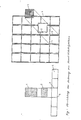
- the figure designed as an exploded drawing shows a 20 cm long monolithic ceramic catalyst element 1 of square cross-section (edge length 150 mm), which is traversed over its entire length by numerous square flow channels in which the exhaust gas to be treated flows and comes into contact with the catalyst.
- This can be a material component of the element or can be present as a coating on the ceramic material of the element.
- a 10 cm deep, intermediate webs 3 having metal cassette 4 made of temperature-resistant steel (for example material V2A) has sections which correspond to the outer shape of monolith and cuff and have a slightly smaller internal free cross-section than the sum of the end faces of the catalyst element and the buffer cuff (158 mm ⁇ 158 mm).
- Each section is provided on the lower edge with opposing stop plates 5, which project 6 mm inwards perpendicular to the web surface and support the edge zone of the monolith face.
- each monolith with a buffer sleeve is pushed into a free section of the metal cassette until the stop plates come into contact with the end face of the monolith.
Landscapes
- Chemical & Material Sciences (AREA)
- Engineering & Computer Science (AREA)
- Materials Engineering (AREA)
- Organic Chemistry (AREA)
- Chemical Kinetics & Catalysis (AREA)
- Exhaust Gas After Treatment (AREA)
- Catalysts (AREA)
- Physical Or Chemical Processes And Apparatus (AREA)
Abstract
Description
- Die Neuerung betrifft eine Vorrichtung zur Halterung von viereckigen, z. B. quadratischen oder rechteckigen monolithischen keramischen Katalysatorelementen zur Herabsetzung des Schadstoffausstoßes von Verbrennungsanlagen, z. B. Feuerungsanlagen für Wärmekraftwerke, sowie zur Zusammenfassung solcher Katalysatorelemente zu einem Paket.
- Keramische Monolithen erfordern wegen ihrer Bruchgefährdung unter extremen Betriebsbedingungen (Erschütterungen, Druckstöße, Temperaturwechsel) eine sichere und stoßabsorbierende Befestigung. Da sie nicht in beliebiger Größe herstellbar sind, besteht weiterhin die Notwendigkeit, mehrere Elemente in einer Batterie zusammen zufassen, um die z. B. bei Kraftwerksabgasen pro Zeiteinheit strömenden großen Gasvolumina durchsetzen zu können.
- Gemäß der Neuerung ist eine Vorrichtung zur Halterung von zur Abgasnachbehandlung von Verbrennungsanlagen verwendeten viereckigen monolithischen keramischen Katalysatorelementen sowie zur Zusammenfassung derselben zu einem Paket gekennzeichnet durch
- a) eine der äußeren Form des Katalysatorelements entsprechende und formschlüssig auf dieses auffschiebbare elastische Puffermanschette
- b) eine in seinen Abteilungen auf der Unter- und Oberseite offenen, der Außenform von Katalysatorelement und Puffermanschette angepaßten, Zwischenstege 3 aufweisende Metallkassette 4, wobei der innere freie Querschnitt jeder Abteilung größer als die Stirnfläche des Katalysatorelements und kleiner als die Summe der Stirnflächen von Katalysatorelement und Puffermanschette oder gleich der Summe dieser Stirnflächen ist, wobei
- c) Kassettentiefe und Höhe der Puffermanschette mindestens 1/5 der Länge des Katalysatorelements entsprechen.
- Die Puffermanschette kann z. B. aus Mineralfaser, Keramikfaser, Drahtgestrick oder anderen temperaturfesten elastischen Werkstoffen bestehen. Nachdem sie auf ein Monolithende von der Monolithstirnseite her aufgeschoben ist, wird der mit der Manschette versehene Monolith in eine freie Abteilung der Metallkassette von oben eingeschoben, wobei die elastische Manschette verdichtet werden kann. Diese Verdichtung kann auch durch ein Manschettenmaterial, welches sich bei Erwärmung einmalig ausdehnt, erreicht oder verstärkt werden. Ein solches Material ist z. B. eine sog. Blähglimmermatte, wie sie z. B. von der Firma 3M unter der Bezeichnung INTERAM ® vertrieben wird. Die erforderliche Wärmebehandlung kann nach der Montage oder aber auch erst im Betrieb durch Beaufschlagung mit heißen Abgasen, z. B. ein heißes Rauchgas, vorgenommen werden. Auf diese Weise werden alle Abteilungen der Metallkassette mit Monolithen gefüllt.
- Soll der Katalysator Betriebsbedingungen ausgesetzt werden, denen die reibschlüssige Verbindung zwischen Monolith und Puffermanschette einerseits und Puffermanschette und Kassettenzwischenstegen andererseits nicht gewachsen sein könnte, so weist nach einer bevorzugten Ausführungsform der Neuerung jede Abteilung der Metallkassette noch auf ihrer Unterseite nach innen gerichtete Anschläge 5 in Form einer die gesamte oder wenigstens gegenüberliegende Teile der Randzone der Stirnfläche des Katalysatorelements übergreifende Fläche auf. Damit wird durch Formschluß eine axiale Verschiebung des Katalysatorelements verhindert.
- Gemäß dieser Ausbildung der Neuerung springen also z. B. an der unteren Stirnseite der Kassettenabteilungen gegenüberliegend angebrachte, gegebenenfalls in mehrere "Zungen" aufgeteilte Anschläge für eine Randzone der Stirnfläche des Katalysatorelements nach innen vor.
- Die Neuerung wird nachfolgend anhand einer vorteilhaften Ausführungsvariante in Verbindung mit der einzigen Figur der Zeichnung weiter erläutert.
- Die als Explosionszeichnung gestaltete Figur zeigt ein 20 cm langes monolithisches keramisches Katalysatorelement 1 von quadratischem Querschnitt (Kantenlänge 150 mm), welches über seine Gesamtlänge von zahlreichen quadratischen Strömungskanälen durchzogen wird, in welchen das zu behandelnde Abgas strömt und mit dem Katalysator in Berührung kommt. Dieser kann stofflicher Bestandteil des Elements sein oder auf dem keramischen Werkstoff des Elements als Beschichtung vorliegen.
- Eine 10 cm lange Puffermanschette 2 aus elastischem Drahtgestrick mit geringfügig kleinerem freien inneren Querschnitt als die Stirnfläche des Monolithen (149 mm × 149 mm) wird auf letzteren so aufgezwängt, daß ihre äußere Stirnfläche bündig mit der Stirnfläche des Monolithen endigt.
- Eine 10 cm tiefe, Zwischenstege 3 aufweisende Metallkassette 4 aus temperaturfestem Stahl (z.B. Werkstoff V2A), weist Abteilungen auf, welche der äußeren Form von Monolith und Manschette entsprechen und einen etwas geringeren inneren freien Querschnitt als die Summe der Stirnflächen von Katalysatorelement und Puffermanschette (158 mm × 158 mm) haben.
- Jede Abteilung ist am unteren Rand mit gegenüberliegenden, jeweils senkrecht zur Stegfläche 6 mm nach innen ragenden und die Randzone der Monolithstirnfläche stützenden Anschlagblechen 5 versehen.
- Bei der Montage wird jeder Monolith mit Puffermanschette in eine freie Abteilung der Metallkassette soweit eingeschoben, bis die Anschlagbleche in Kontakt mit der Monolith-Stirnfläche kommen.
Claims (2)
Priority Applications (1)
| Application Number | Priority Date | Filing Date | Title |
|---|---|---|---|
| AT87101706T ATE64321T1 (de) | 1986-03-01 | 1987-02-07 | Vorrichtung zur halterung von monolithkatalysatoren. |
Applications Claiming Priority (2)
| Application Number | Priority Date | Filing Date | Title |
|---|---|---|---|
| DE8605649U | 1986-03-01 | ||
| DE8605649U DE8605649U1 (de) | 1986-03-01 | 1986-03-01 | Vorrichtung zur Halterung von Monolithkatalysatoren |
Publications (3)
| Publication Number | Publication Date |
|---|---|
| EP0239752A2 true EP0239752A2 (de) | 1987-10-07 |
| EP0239752A3 EP0239752A3 (en) | 1988-11-30 |
| EP0239752B1 EP0239752B1 (de) | 1991-06-12 |
Family
ID=6792273
Family Applications (1)
| Application Number | Title | Priority Date | Filing Date |
|---|---|---|---|
| EP87101706A Expired - Lifetime EP0239752B1 (de) | 1986-03-01 | 1987-02-07 | Vorrichtung zur Halterung von Monolithkatalysatoren |
Country Status (7)
| Country | Link |
|---|---|
| US (1) | US4814146A (de) |
| EP (1) | EP0239752B1 (de) |
| JP (1) | JPS62144543U (de) |
| AT (1) | ATE64321T1 (de) |
| DE (2) | DE8605649U1 (de) |
| ES (1) | ES2000109B3 (de) |
| GR (2) | GR880300025T1 (de) |
Cited By (4)
| Publication number | Priority date | Publication date | Assignee | Title |
|---|---|---|---|---|
| DE3827863A1 (de) * | 1988-08-17 | 1990-02-22 | Leistritz Ag | Katalytische abgasreinigungsvorrichtung |
| DE9013655U1 (de) * | 1990-09-28 | 1990-12-06 | L. & C. Steinmüller GmbH, 5270 Gummersbach | Katalysatorkorbbaugruppe |
| EP0501733A1 (de) * | 1991-02-25 | 1992-09-02 | Ngk Insulators, Ltd. | Abgasentgiftungsanlage |
| DE102011001367A1 (de) * | 2011-03-17 | 2012-09-20 | Thyssenkrupp Polysius Ag | Katalysator für die Rauchgasbehandlung in einer Anlage zur thermischen Behandlung mineralischer Grundstoffe |
Families Citing this family (46)
| Publication number | Priority date | Publication date | Assignee | Title |
|---|---|---|---|---|
| EP0277477B1 (de) * | 1987-01-15 | 1990-05-16 | Emitec Gesellschaft für Emissionstechnologie mbH | Metallischer Katalysator-Trägerkörper mit verkürztem Mantelrohr |
| US5187142A (en) * | 1991-09-03 | 1993-02-16 | General Motors Corporation | Catalytic converter metal monolith |
| US5330728A (en) * | 1992-11-13 | 1994-07-19 | General Motors Corporation | Catalytic converter with angled inlet face |
| JP3110247B2 (ja) * | 1993-06-28 | 2000-11-20 | 日本碍子株式会社 | 除塵装置 |
| SE503352C2 (sv) * | 1994-09-05 | 1996-05-28 | Flaekt Ab | Anordning för fixering av keramiska monolitblock i katalysatorreaktorkammare |
| US5547641A (en) * | 1995-01-10 | 1996-08-20 | Caterpillar Inc. | Catalytic converter exhaust section for an internal combustion engine |
| US5821114A (en) * | 1996-10-10 | 1998-10-13 | Envirogen, Inc. | Biofilter with modular panels and method of using the same |
| US7182924B2 (en) * | 2001-03-13 | 2007-02-27 | Corning Incorporated | Substrate packing for monolith reactors |
| KR100499348B1 (ko) * | 2002-11-05 | 2005-07-04 | 주식회사 엔비켐 | 금속 모노리스형 촉매 모듈 제조를 위한 금속구조체 표면상에 금속-금속산화물 층상입자층의 피복방법 및 촉매부착방법 |
| DE102004027845A1 (de) * | 2004-06-08 | 2006-01-05 | Steag Encotec Gmbh | Anordnung zum Abscheiden von Grobasche aus einem Rauchgasstrom |
| US8101140B2 (en) * | 2008-02-26 | 2012-01-24 | Battelle Memorial Institute | Structured catalyst bed and method for conversion of feed materials to chemical products and liquid fuels |
| US20090293464A1 (en) * | 2008-05-30 | 2009-12-03 | Caterpillar Inc. | Assembly and method of assembly for exhaust treatment |
| US20110030355A1 (en) * | 2009-08-10 | 2011-02-10 | Vconverter Company | Catalytic Converter and Process of Manufacture |
| US9358493B2 (en) * | 2011-03-01 | 2016-06-07 | Exxonmobil Upstream Research Company | Apparatus and systems having an encased adsorbent contactor and swing adsorption processes related thereto |
| DE102014203617A1 (de) * | 2014-02-27 | 2015-08-27 | Johnson Matthey Catalysts (Germany) Gmbh | Katalysatormodul, Aufnahmeeinheit für ein solches Katalysatormodul sowie Verfahren zum Herstellen eines solchen Katalysatormoduls |
| DE102014203618A1 (de) * | 2014-02-27 | 2015-08-27 | Johnson Matthey Catalysts (Germany) Gmbh | Katalysatormodul, Aufnahmeeinheit für ein derartiges Katalysatormodul sowie Verfahren zum Herstellen eines solchen Katalysatormoduls |
| CA3063636C (en) | 2014-07-25 | 2022-03-01 | Exxonmobil Upstream Research Company | Cyclical swing absorption process and system |
| KR20170053682A (ko) | 2014-11-11 | 2017-05-16 | 엑손모빌 업스트림 리서치 캄파니 | 페이스트 임프린트를 통한 고용량 구조체 및 모노리스 |
| US9713787B2 (en) | 2014-12-10 | 2017-07-25 | Exxonmobil Upstream Research Company | Adsorbent-incorporated polymer fibers in packed bed and fabric contactors, and methods and devices using same |
| CN107635644A (zh) | 2014-12-23 | 2018-01-26 | 埃克森美孚上游研究公司 | 结构化吸附床,其生产方法及其用途 |
| SG11201707069QA (en) | 2015-05-15 | 2017-11-29 | Exxonmobil Upstream Res Co | Apparatus and system for swing adsorption processes related thereto comprising mid-bed purge systems |
| CA2979870C (en) | 2015-05-15 | 2019-12-03 | Exxonmobil Upstream Research Company | Apparatus and system for swing adsorption processes related thereto |
| US10124286B2 (en) | 2015-09-02 | 2018-11-13 | Exxonmobil Upstream Research Company | Apparatus and system for swing adsorption processes related thereto |
| CN107847851B (zh) | 2015-09-02 | 2021-05-18 | 埃克森美孚上游研究公司 | 使用脱甲烷塔顶部流作为清扫气体的变化吸附方法和系统 |
| DE102015220126A1 (de) * | 2015-10-15 | 2017-04-20 | Mtu Friedrichshafen Gmbh | Abgaskomponente, Verfahren zum Herstellen einer solchen Abgaskomponente, und Vorrichtung zur Durchführung des Verfahrens |
| CN108348836B (zh) | 2015-10-27 | 2021-01-26 | 埃克森美孚上游研究公司 | 具有多个阀门的变化吸附方法相关的设备和系统 |
| CN108348837B (zh) | 2015-10-27 | 2021-02-19 | 埃克森美孚上游研究公司 | 具有主动控制的进料提升阀和被动控制的产物阀的装置和与其相关的用于摆动吸附方法的系统 |
| AU2016344415B2 (en) | 2015-10-27 | 2019-08-22 | Exxonmobil Upstream Research Company | Apparatus and system for swing adsorption processes related thereto having a plurality of valves |
| CA3005448A1 (en) | 2015-11-16 | 2017-05-26 | Exxonmobil Upstream Research Company | Adsorbent materials and methods of adsorbing carbon dioxide |
| EP3387232B1 (de) * | 2015-12-07 | 2019-11-20 | Johnson Matthey Catalysts (Germany) GmbH | Verbesserte rahmenelemente zur aufnahme von monolithen |
| KR102194968B1 (ko) | 2016-03-18 | 2020-12-28 | 엑손모빌 업스트림 리서치 캄파니 | 관련 스윙 흡착 공정을 위한 장치 및 시스템 |
| JP6442426B2 (ja) * | 2016-03-24 | 2018-12-19 | ヤンマー株式会社 | 触媒反応器及びこれを備えた船舶 |
| AU2017274289B2 (en) | 2016-05-31 | 2020-02-27 | Exxonmobil Upstream Research Company | Apparatus and system for swing adsorption processes |
| CA3025615A1 (en) | 2016-05-31 | 2017-12-07 | Exxonmobil Upstream Research Company | Apparatus and system for swing adsorption processes |
| US10434458B2 (en) | 2016-08-31 | 2019-10-08 | Exxonmobil Upstream Research Company | Apparatus and system for swing adsorption processes related thereto |
| CA3033235C (en) | 2016-09-01 | 2022-04-19 | Exxonmobil Upstream Research Company | Swing adsorption processes for removing water using 3a zeolite structures |
| US10328382B2 (en) | 2016-09-29 | 2019-06-25 | Exxonmobil Upstream Research Company | Apparatus and system for testing swing adsorption processes |
| WO2018118360A1 (en) | 2016-12-21 | 2018-06-28 | Exxonmobil Upstream Research Company | Self-supporting structures having active materials |
| RU2019120009A (ru) | 2016-12-21 | 2021-01-22 | Эксонмобил Апстрим Рисерч Компани | Самоподдерживающиеся структуры, имеющие структуры с геометрией пены и активные материалы |
| WO2019147516A1 (en) | 2018-01-24 | 2019-08-01 | Exxonmobil Upstream Research Company | Apparatus and system for temperature swing adsorption |
| EP3758828A1 (de) | 2018-02-28 | 2021-01-06 | ExxonMobil Upstream Research Company | Vorrichtung und system für wechseladsorptionsprozesse |
| WO2020131496A1 (en) | 2018-12-21 | 2020-06-25 | Exxonmobil Upstream Research Company | Flow modulation systems, apparatus, and methods for cyclical swing adsorption |
| EP3962641A1 (de) | 2019-04-30 | 2022-03-09 | Exxonmobil Upstream Research Company (EMHC-N1-4A-607) | Schnellzyklus-adsorptionsbett |
| WO2021071755A1 (en) | 2019-10-07 | 2021-04-15 | Exxonmobil Upstream Research Company | Adsorption processes and systems utilizing step lift control of hydraulically actuated poppet valves |
| US11433346B2 (en) | 2019-10-16 | 2022-09-06 | Exxonmobil Upstream Research Company | Dehydration processes utilizing cationic zeolite RHO |
| GB201917634D0 (en) * | 2019-12-03 | 2020-01-15 | Johnson Matthey Catalysts Germany Gmbh | Element frame assemblies containing monoliths |
Family Cites Families (16)
| Publication number | Priority date | Publication date | Assignee | Title |
|---|---|---|---|---|
| US1426196A (en) * | 1921-12-14 | 1922-08-15 | Midwest Steel And Supply Compa | Filter |
| CH343762A (de) * | 1956-03-06 | 1959-12-31 | Schirp Wolfgang | Filter für die Reinigung von Gasen, speziell von Luft |
| US3487625A (en) * | 1966-01-17 | 1970-01-06 | Saint Gobain Techn Nouvelles | Filter |
| US3721067A (en) * | 1970-11-12 | 1973-03-20 | B Agnew | Clean air system for hospital operating rooms |
| US4048363A (en) * | 1976-06-16 | 1977-09-13 | Minnesota Mining And Manufacturing Company | Offset laminated intumescent mounting mat |
| JPS556042U (de) * | 1978-06-27 | 1980-01-16 | ||
| US4294806A (en) * | 1979-02-14 | 1981-10-13 | Sakai Chemical Industry Co., Ltd. | Method for preventing the wear of a monolithic catalyst by dusts |
| JPS5684621A (en) * | 1979-12-13 | 1981-07-10 | Mitsubishi Heavy Ind Ltd | Catalyst packaged to rectangular parallelepiped |
| US4347219A (en) * | 1979-12-29 | 1982-08-31 | Honda Giken Kogyo Kabushiki Kaisha | Catalytic converter for exhaust-gas cleaning use and method of assembling same |
| US4335023A (en) * | 1980-01-24 | 1982-06-15 | Engelhard Corporation | Monolithic catalyst member and support therefor |
| US4419108A (en) * | 1982-02-22 | 1983-12-06 | Corning Glass Works | Filter apparatus and method of filtering |
| US4416675A (en) * | 1982-02-22 | 1983-11-22 | Corning Glass Works | High capacity solid particulate filter apparatus |
| DE3330132A1 (de) * | 1983-08-20 | 1985-02-28 | H. Krantz Gmbh & Co, 5100 Aachen | Rahmen |
| US4561954A (en) * | 1985-01-22 | 1985-12-31 | Avx Corporation | Method of applying terminations to ceramic bodies |
| US4663934A (en) * | 1985-04-01 | 1987-05-12 | Arvin Industries, Inc. | Manifold exhaust processor |
| US4636232A (en) * | 1985-12-16 | 1987-01-13 | Amway Corporation | Filter stack |
-
1986
- 1986-03-01 DE DE8605649U patent/DE8605649U1/de not_active Expired
-
1987
- 1987-02-07 ES ES87101706T patent/ES2000109B3/es not_active Expired - Lifetime
- 1987-02-07 AT AT87101706T patent/ATE64321T1/de not_active IP Right Cessation
- 1987-02-07 EP EP87101706A patent/EP0239752B1/de not_active Expired - Lifetime
- 1987-02-07 DE DE8787101706T patent/DE3770672D1/de not_active Expired - Lifetime
- 1987-02-24 US US07/018,247 patent/US4814146A/en not_active Expired - Fee Related
- 1987-03-02 JP JP1987028924U patent/JPS62144543U/ja active Pending
-
1988
- 1988-05-20 GR GR88300025T patent/GR880300025T1/el unknown
-
1991
- 1991-06-13 GR GR91400814T patent/GR3002139T3/el unknown
Cited By (5)
| Publication number | Priority date | Publication date | Assignee | Title |
|---|---|---|---|---|
| DE3827863A1 (de) * | 1988-08-17 | 1990-02-22 | Leistritz Ag | Katalytische abgasreinigungsvorrichtung |
| DE9013655U1 (de) * | 1990-09-28 | 1990-12-06 | L. & C. Steinmüller GmbH, 5270 Gummersbach | Katalysatorkorbbaugruppe |
| EP0501733A1 (de) * | 1991-02-25 | 1992-09-02 | Ngk Insulators, Ltd. | Abgasentgiftungsanlage |
| US5228892A (en) * | 1991-02-25 | 1993-07-20 | Ngk Insulators, Ltd. | Exhaust emission control device |
| DE102011001367A1 (de) * | 2011-03-17 | 2012-09-20 | Thyssenkrupp Polysius Ag | Katalysator für die Rauchgasbehandlung in einer Anlage zur thermischen Behandlung mineralischer Grundstoffe |
Also Published As
| Publication number | Publication date |
|---|---|
| DE8605649U1 (de) | 1986-04-17 |
| DE3770672D1 (de) | 1991-07-18 |
| ES2000109A4 (es) | 1987-12-16 |
| JPS62144543U (de) | 1987-09-11 |
| EP0239752A3 (en) | 1988-11-30 |
| US4814146A (en) | 1989-03-21 |
| ATE64321T1 (de) | 1991-06-15 |
| GR3002139T3 (en) | 1992-12-30 |
| GR880300025T1 (en) | 1988-10-18 |
| EP0239752B1 (de) | 1991-06-12 |
| ES2000109B3 (es) | 1992-01-01 |
Similar Documents
| Publication | Publication Date | Title |
|---|---|---|
| EP0239752B1 (de) | Vorrichtung zur Halterung von Monolithkatalysatoren | |
| DE19504208B4 (de) | Abgaskonverter mit einem Katalysator und einem diesem vorgeschalteten Brenner | |
| DE102006024778B3 (de) | Statischer Mischer und Abgasbehandlungseinrichtung | |
| EP0542002B1 (de) | Katalysator für die Abgase eines Verbrennungsmotors | |
| DE2257968A1 (de) | Vorrichtung zur reinigung der abgase von verbrennungsmotoren, insbesondere dieselmotoren | |
| EP1728984A2 (de) | Abgasanlage | |
| EP2457053A1 (de) | Latentwärmespeicherkatalysator für abgasanlage einer brennkraftmaschine | |
| DE102018106588A1 (de) | Abgasanlage sowie Verfahren zum Betreiben einer Abgasanlage | |
| DE19900310B4 (de) | Katalytischer Konverter für einen Schalldämpfer eines Kleinmotors | |
| EP0233509B1 (de) | Vorrichtung zur Halterung von Monolithkatalysatoren | |
| WO2008135175A1 (de) | Abgasreinigungsvorrichtung für eine abgasanlage | |
| DE19504851B4 (de) | Abgaskonverter mit einem Vorkatalysator und einem Hauptkatalysator | |
| DE10350695A1 (de) | Abgasreinigungssystem mit Partikelfilter | |
| DE3922667A1 (de) | Vorrichtung zur katalytischen entgiftung oder dgl. von verbrennungsmotor-abgasen mit doppelwandigem gehaeuse | |
| EP1012455B1 (de) | Katalytischer konverter für einen kleinmotor | |
| DE69304746T2 (de) | Verfahren zur Herstellung eines katalytischen Konverters zur Abgasreinigung | |
| EP1789189A1 (de) | Metallfolie mit unterschiedlichen einbuchtungen | |
| DE2248442A1 (de) | Katalysator zur katalytischen reinigung von abgasen | |
| EP1922148B1 (de) | Verfahren zur herstellung eines ringförmigen wabenkörpers, sowie ringförmiger wabenkörper | |
| EP0719912B1 (de) | Abgasbehandlungsvorrichtung für Verbrennungsmotorenabgase | |
| DE2259817A1 (de) | Katalysator zur katalytischen reinigung von abgasen | |
| DE4002649A1 (de) | Verfahren zum verschliessen einzelner kanaele eines keramischen wabenkoerpers | |
| WO2009016006A1 (de) | Abgasanlage einer brennkraftmaschine | |
| EP1577515B1 (de) | Vorrichtung zum Reinigen von Fahrzeugabgasen | |
| EP0191343A2 (de) | Zentriermanschette zum Setzen von Kaminrohren |
Legal Events
| Date | Code | Title | Description |
|---|---|---|---|
| PUAI | Public reference made under article 153(3) epc to a published international application that has entered the european phase |
Free format text: ORIGINAL CODE: 0009012 |
|
| 17P | Request for examination filed |
Effective date: 19870207 |
|
| AK | Designated contracting states |
Kind code of ref document: A2 Designated state(s): AT BE CH DE ES FR GB GR IT LI LU NL SE |
|
| ITCL | It: translation for ep claims filed |
Representative=s name: BARZANO' E ZANARDO ROMA S.P.A. |
|
| EL | Fr: translation of claims filed | ||
| TCNL | Nl: translation of patent claims filed | ||
| PUAL | Search report despatched |
Free format text: ORIGINAL CODE: 0009013 |
|
| AK | Designated contracting states |
Kind code of ref document: A3 Designated state(s): AT BE CH DE ES FR GB GR IT LI LU NL SE |
|
| 17Q | First examination report despatched |
Effective date: 19890901 |
|
| GRAA | (expected) grant |
Free format text: ORIGINAL CODE: 0009210 |
|
| AK | Designated contracting states |
Kind code of ref document: B1 Designated state(s): AT BE CH DE ES FR GB GR IT LI LU NL SE |
|
| PG25 | Lapsed in a contracting state [announced via postgrant information from national office to epo] |
Ref country code: SE Effective date: 19910612 |
|
| REF | Corresponds to: |
Ref document number: 64321 Country of ref document: AT Date of ref document: 19910615 Kind code of ref document: T |
|
| ITF | It: translation for a ep patent filed | ||
| REF | Corresponds to: |
Ref document number: 3770672 Country of ref document: DE Date of ref document: 19910718 |
|
| ET | Fr: translation filed | ||
| GBT | Gb: translation of ep patent filed (gb section 77(6)(a)/1977) | ||
| REG | Reference to a national code |
Ref country code: ES Ref legal event code: FG2A Ref document number: 2000109 Country of ref document: ES Kind code of ref document: B3 |
|
| PGFP | Annual fee paid to national office [announced via postgrant information from national office to epo] |
Ref country code: LU Payment date: 19920115 Year of fee payment: 6 Ref country code: DE Payment date: 19920115 Year of fee payment: 6 |
|
| PGFP | Annual fee paid to national office [announced via postgrant information from national office to epo] |
Ref country code: GR Payment date: 19920116 Year of fee payment: 6 |
|
| PGFP | Annual fee paid to national office [announced via postgrant information from national office to epo] |
Ref country code: GB Payment date: 19920127 Year of fee payment: 6 |
|
| PGFP | Annual fee paid to national office [announced via postgrant information from national office to epo] |
Ref country code: ES Payment date: 19920201 Year of fee payment: 6 |
|
| PGFP | Annual fee paid to national office [announced via postgrant information from national office to epo] |
Ref country code: AT Payment date: 19920211 Year of fee payment: 6 |
|
| PGFP | Annual fee paid to national office [announced via postgrant information from national office to epo] |
Ref country code: CH Payment date: 19920217 Year of fee payment: 6 |
|
| PGFP | Annual fee paid to national office [announced via postgrant information from national office to epo] |
Ref country code: BE Payment date: 19920219 Year of fee payment: 6 |
|
| PGFP | Annual fee paid to national office [announced via postgrant information from national office to epo] |
Ref country code: SE Payment date: 19920226 Year of fee payment: 6 |
|
| PGFP | Annual fee paid to national office [announced via postgrant information from national office to epo] |
Ref country code: FR Payment date: 19920227 Year of fee payment: 6 |
|
| PGFP | Annual fee paid to national office [announced via postgrant information from national office to epo] |
Ref country code: NL Payment date: 19920229 Year of fee payment: 6 |
|
| PLBE | No opposition filed within time limit |
Free format text: ORIGINAL CODE: 0009261 |
|
| STAA | Information on the status of an ep patent application or granted ep patent |
Free format text: STATUS: NO OPPOSITION FILED WITHIN TIME LIMIT |
|
| 26N | No opposition filed | ||
| EPTA | Lu: last paid annual fee | ||
| REG | Reference to a national code |
Ref country code: GR Ref legal event code: FG4A Free format text: 3002139 |
|
| PG25 | Lapsed in a contracting state [announced via postgrant information from national office to epo] |
Ref country code: LU Free format text: LAPSE BECAUSE OF NON-PAYMENT OF DUE FEES Effective date: 19930207 Ref country code: GB Effective date: 19930207 Ref country code: AT Effective date: 19930207 |
|
| PG25 | Lapsed in a contracting state [announced via postgrant information from national office to epo] |
Ref country code: ES Free format text: LAPSE BECAUSE OF NON-PAYMENT OF DUE FEES Effective date: 19930208 |
|
| PG25 | Lapsed in a contracting state [announced via postgrant information from national office to epo] |
Ref country code: LI Effective date: 19930228 Ref country code: CH Effective date: 19930228 Ref country code: BE Effective date: 19930228 |
|
| BERE | Be: lapsed |
Owner name: DEGUSSA A.G. Effective date: 19930228 |
|
| PG25 | Lapsed in a contracting state [announced via postgrant information from national office to epo] |
Ref country code: GR Free format text: THE PATENT HAS BEEN ANNULLED BY A DECISION OF A NATIONAL AUTHORITY Effective date: 19930831 |
|
| PG25 | Lapsed in a contracting state [announced via postgrant information from national office to epo] |
Ref country code: NL Effective date: 19930901 |
|
| GBPC | Gb: european patent ceased through non-payment of renewal fee |
Effective date: 19930207 |
|
| NLV4 | Nl: lapsed or anulled due to non-payment of the annual fee | ||
| PG25 | Lapsed in a contracting state [announced via postgrant information from national office to epo] |
Ref country code: FR Effective date: 19931029 |
|
| REG | Reference to a national code |
Ref country code: CH Ref legal event code: PL |
|
| PG25 | Lapsed in a contracting state [announced via postgrant information from national office to epo] |
Ref country code: DE Effective date: 19931103 |
|
| REG | Reference to a national code |
Ref country code: FR Ref legal event code: ST |
|
| REG | Reference to a national code |
Ref country code: GR Ref legal event code: MM2A Free format text: 3002139 |
|
| REG | Reference to a national code |
Ref country code: ES Ref legal event code: FD2A Effective date: 19990201 |
|
| PG25 | Lapsed in a contracting state [announced via postgrant information from national office to epo] |
Ref country code: IT Free format text: LAPSE BECAUSE OF NON-PAYMENT OF DUE FEES Effective date: 20050207 |