EP0236583B1 - System für Luftfahrtelektroniksteuerung - Google Patents
System für Luftfahrtelektroniksteuerung Download PDFInfo
- Publication number
- EP0236583B1 EP0236583B1 EP86200408A EP86200408A EP0236583B1 EP 0236583 B1 EP0236583 B1 EP 0236583B1 EP 86200408 A EP86200408 A EP 86200408A EP 86200408 A EP86200408 A EP 86200408A EP 0236583 B1 EP0236583 B1 EP 0236583B1
- Authority
- EP
- European Patent Office
- Prior art keywords
- control
- signal
- data bus
- actuator
- segment
- Prior art date
- Legal status (The legal status is an assumption and is not a legal conclusion. Google has not performed a legal analysis and makes no representation as to the accuracy of the status listed.)
- Expired
Links
- 230000033001 locomotion Effects 0.000 claims description 27
- RZVHIXYEVGDQDX-UHFFFAOYSA-N 9,10-anthraquinone Chemical compound C1=CC=C2C(=O)C3=CC=CC=C3C(=O)C2=C1 RZVHIXYEVGDQDX-UHFFFAOYSA-N 0.000 claims description 16
- 238000004891 communication Methods 0.000 claims description 13
- 238000006073 displacement reaction Methods 0.000 claims description 8
- 230000008859 change Effects 0.000 claims description 7
- 230000003750 conditioning effect Effects 0.000 claims description 7
- 101100039010 Caenorhabditis elegans dis-3 gene Proteins 0.000 claims description 6
- 101100172874 Caenorhabditis elegans sec-3 gene Proteins 0.000 claims 1
- 230000003247 decreasing effect Effects 0.000 claims 1
- 101150088659 mal3 gene Proteins 0.000 claims 1
- 210000000707 wrist Anatomy 0.000 description 17
- 230000007935 neutral effect Effects 0.000 description 12
- 230000007246 mechanism Effects 0.000 description 11
- 238000010586 diagram Methods 0.000 description 8
- 230000000694 effects Effects 0.000 description 5
- 230000003416 augmentation Effects 0.000 description 4
- 230000002950 deficient Effects 0.000 description 4
- 238000013461 design Methods 0.000 description 4
- 238000011161 development Methods 0.000 description 4
- 230000007257 malfunction Effects 0.000 description 4
- 230000004044 response Effects 0.000 description 4
- 239000000523 sample Substances 0.000 description 4
- 230000003068 static effect Effects 0.000 description 4
- 102220492605 Numb-like protein_S17A_mutation Human genes 0.000 description 3
- 238000009434 installation Methods 0.000 description 3
- 238000000034 method Methods 0.000 description 3
- 238000013459 approach Methods 0.000 description 2
- 238000006243 chemical reaction Methods 0.000 description 2
- 229910017052 cobalt Inorganic materials 0.000 description 2
- 239000010941 cobalt Substances 0.000 description 2
- 238000005516 engineering process Methods 0.000 description 2
- 239000012530 fluid Substances 0.000 description 2
- 238000004519 manufacturing process Methods 0.000 description 2
- 230000003534 oscillatory effect Effects 0.000 description 2
- 238000004513 sizing Methods 0.000 description 2
- 239000003381 stabilizer Substances 0.000 description 2
- XUKUURHRXDUEBC-KAYWLYCHSA-N Atorvastatin Chemical compound C=1C=CC=CC=1C1=C(C=2C=CC(F)=CC=2)N(CC[C@@H](O)C[C@@H](O)CC(O)=O)C(C(C)C)=C1C(=O)NC1=CC=CC=C1 XUKUURHRXDUEBC-KAYWLYCHSA-N 0.000 description 1
- 101100084503 Caenorhabditis elegans pas-3 gene Proteins 0.000 description 1
- 101100504379 Mus musculus Gfral gene Proteins 0.000 description 1
- 101100400378 Mus musculus Marveld2 gene Proteins 0.000 description 1
- 230000009471 action Effects 0.000 description 1
- 229910000828 alnico Inorganic materials 0.000 description 1
- 230000003321 amplification Effects 0.000 description 1
- 230000003190 augmentative effect Effects 0.000 description 1
- 230000008901 benefit Effects 0.000 description 1
- 230000005540 biological transmission Effects 0.000 description 1
- 150000001768 cations Chemical class 0.000 description 1
- GUTLYIVDDKVIGB-UHFFFAOYSA-N cobalt atom Chemical compound [Co] GUTLYIVDDKVIGB-UHFFFAOYSA-N 0.000 description 1
- 238000001816 cooling Methods 0.000 description 1
- 230000001351 cycling effect Effects 0.000 description 1
- 238000013016 damping Methods 0.000 description 1
- 230000009977 dual effect Effects 0.000 description 1
- 238000010438 heat treatment Methods 0.000 description 1
- 238000010348 incorporation Methods 0.000 description 1
- 230000006698 induction Effects 0.000 description 1
- 230000001939 inductive effect Effects 0.000 description 1
- 230000002452 interceptive effect Effects 0.000 description 1
- 238000006386 neutralization reaction Methods 0.000 description 1
- 238000003199 nucleic acid amplification method Methods 0.000 description 1
- 238000010248 power generation Methods 0.000 description 1
- 238000003825 pressing Methods 0.000 description 1
- 238000012545 processing Methods 0.000 description 1
- 230000009467 reduction Effects 0.000 description 1
- 238000000926 separation method Methods 0.000 description 1
- 238000007493 shaping process Methods 0.000 description 1
- 230000006641 stabilisation Effects 0.000 description 1
- 238000011105 stabilization Methods 0.000 description 1
- 230000000007 visual effect Effects 0.000 description 1
Images


Classifications
-
- B—PERFORMING OPERATIONS; TRANSPORTING
- B64—AIRCRAFT; AVIATION; COSMONAUTICS
- B64C—AEROPLANES; HELICOPTERS
- B64C13/00—Control systems or transmitting systems for actuating flying-control surfaces, lift-increasing flaps, air brakes, or spoilers
- B64C13/24—Transmitting means
- B64C13/38—Transmitting means with power amplification
- B64C13/50—Transmitting means with power amplification using electrical energy
- B64C13/503—Fly-by-Wire
-
- B—PERFORMING OPERATIONS; TRANSPORTING
- B64—AIRCRAFT; AVIATION; COSMONAUTICS
- B64C—AEROPLANES; HELICOPTERS
- B64C13/00—Control systems or transmitting systems for actuating flying-control surfaces, lift-increasing flaps, air brakes, or spoilers
- B64C13/24—Transmitting means
- B64C13/38—Transmitting means with power amplification
- B64C13/50—Transmitting means with power amplification using electrical energy
- B64C13/505—Transmitting means with power amplification using electrical energy having duplication or stand-by provisions
-
- G—PHYSICS
- G05—CONTROLLING; REGULATING
- G05D—SYSTEMS FOR CONTROLLING OR REGULATING NON-ELECTRIC VARIABLES
- G05D1/00—Control of position, course, altitude or attitude of land, water, air or space vehicles, e.g. using automatic pilots
- G05D1/0055—Control of position, course, altitude or attitude of land, water, air or space vehicles, e.g. using automatic pilots with safety arrangements
- G05D1/0077—Control of position, course, altitude or attitude of land, water, air or space vehicles, e.g. using automatic pilots with safety arrangements using redundant signals or controls
-
- Y—GENERAL TAGGING OF NEW TECHNOLOGICAL DEVELOPMENTS; GENERAL TAGGING OF CROSS-SECTIONAL TECHNOLOGIES SPANNING OVER SEVERAL SECTIONS OF THE IPC; TECHNICAL SUBJECTS COVERED BY FORMER USPC CROSS-REFERENCE ART COLLECTIONS [XRACs] AND DIGESTS
- Y02—TECHNOLOGIES OR APPLICATIONS FOR MITIGATION OR ADAPTATION AGAINST CLIMATE CHANGE
- Y02T—CLIMATE CHANGE MITIGATION TECHNOLOGIES RELATED TO TRANSPORTATION
- Y02T50/00—Aeronautics or air transport
- Y02T50/50—On board measures aiming to increase energy efficiency
Definitions
- each autonomous subsystem e.g. force-control stick flight controller, rudder pedal assembly spoiler actua3 tor, elevator actuator, etc.
- RACU Remote Acquisition and Control Unit
- the RACU exists in the primary flight control system for providing: data encoding/decoding, data transmitting/receiving, data acquisition, actuator control and redundancy management functions.
- tubing or lines carrying pressurized hydraulic fluid and the control valves are sized to permit a maximum flow of pressurized hydraulic fluid in order to produce both the greatest hinge moment likely to be required and the predetermined maximum angle-of-deflection rate of the aerodynamic control surface.
- both a large angle-of-deflection range and a high angle-of-3 deflection rate of aerodynamic control surface movement are required.
- the invention which is defined in claim 1, relates to an electronic flight con3 trol system for an aircraft and, more particularly, to a multi-data bus or a multi-channel redundancy fly-by-wire system with complete channel separation and no automatic switching of data or control information between the channels.
- the control system management philosophy is based on the redundant control system of an airplane being able to sustain a failure of any one segment of a multi-segmented control surface.
- an electro-hydraulic or electro-mechanical type of power actuator to freeze and/or produce a hard-over actuation of a control surface segment, and this could be disas3 trous during high speed flight. Therefore, in the event of such a failure, the rapid neutralization of the defective PA can convert an active failure which is either of the hard-over or oscillatory type into a pas3 sive and neutralized control surface segment failure.
- the loss of one PA and its respective control surface segment may leave the total multi-segmented control surface with a degraded operational capability; however, those PAs and their control surface segments which remain operational would be safely active.
- the flight control system can be adapted to tolerate a second PA failure, providing that it also can be quickly neutralized or rendered passive.
- the present invention provides in one embodiment a multi-segmented elevator control surface comprising: redundant elec3 tronic circuits and PAs providing an angle-of-deflection movement of their respective control surface segments, and wherein the redundancy is further implemented by each of the control surface segments having a gain con3 trol power module (GCPM) which incorporates means for passivating its control surface segment upon PA failure.
- GCPM gain con3 trol power module
- the GCPM in addition to being capable of passivating its control surface segment, is also effective in minimizing structural deflection and structural stress load effects from hard-over control inputs due to PA failure at high flight speed, and this is accomplished through the incorporation of a ratio-change mechanism which modulates the effective output movement of the PA.
- the ratio or the gain of a control surface segment angle-of-deflection range of movement relative to its PA range of travel can be adjusted by means of the ratio-3 change mechanism.
- the highest value of gain obtain3 able by the GCPM is "one”, and that this will result in the maximum range of angle-of-deflection travel of the control surface segment relative to its PA range of travel.
- the low3 est value of gain obtainable by the GCPM is "zero” and that this will result in a nulling or zero-deflection of the control surface segment relative to PA travel. Therefore, control authority of the PA over the control surface segment is limited by the GCPM between the gain adjustment positions of "zero" and "one".
- electro-hydraulic and electro-mechanical power actuators have a finite probability of failure; therefore, an object is to passivate the actuation or active failure effects such as: hard-overs, oscillatory, jammed, jammed in a deflected position, and severed.
- an electronically redundant control circuit uti3 lizing GCPMs are incorporated for producing the passive failure result.
- Another object is to adjust the GCPM to suit var- ia3 tions in airspeed and for maintaining a predetermined, relatively constant, "control stick force per 'g' char3 acteristic" over the entire flight regime of the airplane.
- Another object is to increase control force stiff3 ness and provide a finer control over control surface deflection with increasing flight speed, thereby helping to prevent control surface flutter at high airspeeds and limit cycling of the automatic flight controls at cruise flight speeds.
- Another object is to convert a potentially hazard3 ous failure in the flight control system into a passive failure with only a fraction of the total control sur3 face area being neutralized.
- Another object is to limit the authority of a power actuator by minimizing the deflection rate of an aero3 dynamic surface and minimizing the angular degree range of deflection as the flight speed increases in order to prevent structural damage during conditions of high dynamic pressure acting on the aerodynamic surface, such as the event of hard-over failure.
- Another object is to automatically match the im- ped3 ance of the control surface angle-of-deflection rate to the hinge force moments produced in relation to flight speed. This permits the use of lower powered actuators because a large angle-of-deflection range of movement of a control surface segment is not coincident with large hinge force moments. Further, this impedance matching eliminates the present known method of designing PAs which is to provide maximum torque at both the highest angle-of-deflection rate and through the greatest range of movement.
- An advantage of an all-electric, redundant, flight control system is that it is much easier to run multiple electrical lines for damage control than it is to run multiple mechanical lines, which are also heavier.
- Total electrical failure would be the only eventu3 ality that could cause a complete failure of the re- dun3 dant all-electronic control system.
- engine driven main generators generally have a back-up such as ram air driven generators and/or standby APU (Auxiliary Power Unit) driven generators; and the ultimate standy source is the aircraft's batteries.
- APU Advanced Power Unit
- FIG. 1 is a schematic diagram of a fly-by-wire, quad-redundancy, data bus elevator control system which is a subsystem of an all-electric flight control system of an aircraft.
- the elevator control system is basi3 cally separated into two categories: (1) electronics, and (2) mechanics; and they become linked together through GCPMs (Gain Control Power Modules) 10-10C, located adjacent to each elevator control surface segment 11-11 C, respectively.
- GCPMs Gain Control Power Modules
- the pilot's and copilot's manual control input generally controls a servo valve of a main power output actuator unit or main actuator; and this main actuator is normally located at some distance from the aerodynamic surface being con3 trollably actuated.
- a linkage or cable system generally provides the interconnection between the main actuator and the control surface; and the support mounting for the linkage or cable system, to fixed structure of the airplane, is designed and sized for accommodating the greatest or the maximum control loads to be encountered.
- An important aspect of the present invention is that a gain change by each GCPM 10-10C takes place in the main load path between a power actuator 12-12C and its respective aerodynamic surface segment 11-11 C being controllably actuated.
- an important aspect of the present invention is an authority limitation on the angle-of-deflection range, coupled with a variation in the control force applied to each segment of an elevator control surface, and this is accomplished through the GCPMs 10-10C.
- the pilot's and copilot's manual control input is initiated through two sets of dual wrist controllers (13, 13A) and (13B, 13C), respectively, which have both longitudinal and lateral angular movement and, through their respective wrist control stick position sensors or transducers 14-14C, generate a command signal S13-S13C, respectively, which is sent to RACUs (Remote Acquisition and Control Units) 15-15C, respectively.
- the wrist con3 trollers 13-13C are used primarily for the command con3 trol signal input S13-S13C to the airplane's pitch and roll axis.
- Wrist controllers 13-13C are compact input devices much less costly to manufacture than the control wheel and column combinations customarily installed in com3 flashal transport airplanes. As in the case of the con3 trol wheel and column where the copilot's wheel and column follow the control-input motions made by the pilot, and vice versa, if only one wrist controller is deflected by one of the pilots, the other three will also be deflected, precisely following the motions of the controller actuated by the pilot.
- the means ensuring this ganging of the wrist controllers can be mechanical in nature, or in order to help preserve a large amount of cockpit real estate, can be an electro-3 mechanical servo system.
- One type of wrist controller device could basically comprise a positioning servo with a high degree of stiffness, which receives a deflection command signal that is obtained by algebraically summing output signals of force sensors attached to each of the wrist controllers; and the force sensors combined with signal conditioning circuits would be dualized for moni3 toring purposes.
- Each individual wrist controller 13-13C in com3 bination with its position transducer 14-14C, respec3 tively, generates an independent bipolar, longitudinal and lateral, command signal S13-S13C, thereby providing a quad-redundancy control input to a longitudinal pri3 mary flight control system which activates a quad-seg3 mented elevator control surface 11-11C in the empennage section of the airplane.
- Each of the four data buses 16-16C connects four data bus couplers C1-C4 which are associated with components as follows: C1 is associated with both pairs of wrist controllers 13-13C and pitot static probes 17-17A; C2 is associated with API (Actuator Performance Indicator) 18; C3 is associated with PAs 12-12C; and C4 is associated with GCPMs 10-10C.
- the four data bus couplers C1-C4 are attached to a data bus medium 16-16C by means of induc3 tive couplers.
- the current-mode data bus 16-16C and the inductive data bus couplers C1-C4 are of the type described in U.S. Patent No. 4,264,827 issued on April 28, 1981 to H. K. Herzog.
- the data bus terminals T/R 19-19C, 20-20C, 21-21C, 22-22C are of the autonomous access type and utilize DATAC (Digital Autonomous Termi3 nal Access Communication) protocol as described in U.S. Patent No. 4,199,663 issued on April 22, 1980 to H. K. Herzog; and, as more fully described therein, recent development work on data bus terminal design has pro3 prised an effective terminal monitor which will prevent jamming of the data bus and alert the flight deck crew of the defective unit.
- DATAC Digital Autonomous Termi3 nal Access Communication
- Each pair of wrist con3 trollers (13, 13A) and (13B, 13C) feed a dualized com3 mand signal (S13-S13A) and (S13B-S13C), respectively, into RACUs 15-15C, which are, in essence, small data computers that house several circuit boards complete with connector and electrical heating/cooling provisions.
- Each of these RACUs 15-15C is also a pre3 amplifier and pre-processor, containing signal-condi3 tioning and power-conversion means.
- the RACUs 15-15C may vary in capacity and size in order to accommodate local data handling, computation, control and power amplification requirements.
- the airspeed of the airplane is sensed by two pitot tubes 17, 17A having air data transducers 23, 23A, respectively, which are positioned one on each side of the airplane; and these are dedicated to provide dual3 ized air data signals S17, S17A, respectively, which signals are fed into RACUs 15-15C.
- the air data signals S17, S17A from transducers 23, 23A, respectively, are accommodated by the same RACUs 15-15C as the wrist con3 troller signals S13-S13C, as shown, or they may be accommodated by separate RACUs 24-24C.
- the RACUs 15-15C output signals enter T/Rs 19-19C, respectively; and each T/R 19-19C output signal is put onto one of four data buses 16-16C through data bus coupler C1.
- data buses 16-16C are of the current-mode type utilizing induction bus couplers Cl-C4 and described in U.S. Patent No. 4,264,827 issued on April 28, 1981 to H. K. Herzog.
- Each of the T/Rs contains electronic firmware which is pre-programmed for each of the data bus couplers and sends out addresses to the local subsystem devices to fetch the data pieces. Also, contained within this electronic firmware is an information circuit which sends out a label to the data bus preceding the data to be transmitted so that, in essence, the data is identi3 fied by said label.
- the first type of RACUs 25-25C, coupled with T/Rs 21-21 C, respectively, have standard power conversion and data handling provisions and, in addition, contain position control circuits and power drive electronics for PAs 12-12C.
- the second type of RACUs 26-26C, coupled with T/Rs 22-22C, respectively, also have standard power conver3 sion and data handling provisions and, essentially, per3 form functions similar to the first type of RACUs and, in addition, contain position control circuits and power drive electronics for GAAM (Gain Authority Adjust Motors) 27-27C within the GCPMs 10-10C.
- GAAM Gain Authority Adjust Motors
- a GCPM control circuitry located within the second type, RACUs 26-26C, is a GCPM control circuitry which will accommodate the signal commands from the wrist controllers 13-13C and the air data sig3 nals S17, S17A and, in turn, relay the actual present position of each of the control surface segments 11-11C back to the data buses 16-16C for use by the pilot's and copilot's API 18; i.e., the resulting displacement of each of the control surface segments 11-11C is fed into API 18, which performs many important functions.
- the pilot and copilot's API 18 i.e., the resulting displacement of each of the control surface segments 11-11C is fed into API 18, which performs many important functions.
- it displays to the pilot and copilot the actual present position of each of the PAs 12-12C, together with their respective commanded or scheduled values.
- a warning means will alert the pilot and copilot to any related discrepancy and also provide a detailed visual indication of the fault situation.
- special control means such as buttons, levers or switches, the pilot and/or the copilot will be able to de-activate individual flight control surface segments 11-11C.
- FIGS. 2A and 2B combined, form a detailed block diagram description of a single channel or a single data bus 16 of the multi-data bus elevator control system shown in FIG. 1, and the single data bus 16 services one control surface segment 11 of a multi- segment elevator control surface. It should be understood that this diagram merely depicts the electronic control circuit and does not include the electrical power system.
- data bus 16 follows the electronic signal flow from the pilot's control stick or wrist controller 13, through RACU 15, T/R 19, to data bus 16; from data bus 16, through T/R 21 and RACU 25, to PA 12 with GCPM 10 in its output control path; and from GCPM 10, a feedback signal is sent through RACU 26, T/R 22, to data bus 16; and from data bus 16, the feedback signal is sent through T/R 20, RACU 24, to the pilot's and copilot's redundancy management API 18.
- the pilot's wrist controller 13 contains, amongst other things, a position sensor 14 for the airplane pitch axis; the position sen3 sor 14 sends a signal S13 into a signal conditioning circuit 30 in RACU 15.
- the signal S13 may be analog to begin with, so the signal conditioning circuit 30 con3 verts the signal S13 to a digital format in order for it to be compatible with T/R 19.
- the data bus terminal T/R 19 is of the autonomous access type which utilizes DATAC (Digital Autonomous Terminal Access Communication) as described in U.S. Patent No. 4,199,663 issued April 22, 1980 to H. K. Herzog.
- DATAC Digital Autonomous Terminal Access Communication
- RACU 15 also contains a second signal conditioning circuit 31 which receives an air impact pressure signal S17 from transducer 23 which is connected to pitot static probe 17.
- the signal S17 may also be analog, so it will have to be converted by the second signal condi3 tioning circuit 31 to a digital format in order for it to be compatible with T/R 19.
- Both the pilot's input signal S13 and the air impact pressure signal S17 are sent from T/R 21 to RACU 25 which is an electronic con3 trol unit for PA 12.
- RACU 25 depicts a typical electronic control system for an electro-mechanical actuator, wherein the main control signal inputs are: the pilot's control signal S13; the air impact pressure signal S17; the pilot's nulling discrete signal S18; a data bus lost com- munica3 tion signal S21; and a pitch augmentation signal S32 from a pitch augmentation system (not shown).
- the air impact pressure signal S17 is sent into a function generator 33 which sends a signal to a multiplier 34.
- Multiplier 34 also receives the pilot's input signal S13 from T/R 21. Both the multi3 plier 34 and the function generator 33 are inserted in the FIGS. 2A and 2B diagram for the purpose of addition3 ally shaping the pilot's input signal S13 on the basis of the air impact pressure signal S17.
- the multiplier 34 output signal goes into a summer 35 which also receives a signal S32 from RACU 24.
- This particular signal S32 is not originated or transmitted by any unit or station shown in the FIGS. 2A and 2B diagram; and it is included herein for the situa3 tion where an augmentation signal from some pitch aug3 mentation system (not shown) would be algebraically added in series, with the pilot's input signal S13, to form the final command signal to MCU (Motor Control Unit) 36 of PA 12.
- MCU Motor Control Unit
- the summer 35 sends the main command signal to a forward path compensator 37, a summer 38, an amplifier 39, and to MCU 36 of PA 12.
- the MCU 36 because of its large power dissipation, is a self-contained unit and is shown in a separate block diagram.
- the output from MCU 36 is connected to a brushless DC motor 41 that powers PA 12.
- the motor 41 output shaft drives a gearbox 42 having a jackscrew-3 driven output rod which connects to both a position sen3 sor 43 and a gain control mechanism 44 of GCPM 10.
- Position sensor 43 is a rotary transducer having a digital output signal and sends a position feedback signal S43 from PA 12 to both the summer 38 and to a signal conditioner 45.
- the signal conditioner 45 makes the position feedback signal S43 available to T/R 21 for the purpose of transmitting it onto data bus 16.
- hydro-mechanical and electro-mechanical actuators have a certain degree of lag or sluggishness in their performance due to inertia forces involved in the piston or motor and drive mechanism; and to correct this lag response problem, a lead term signal is added to the main command signal from summer 38 within the forward path compensation circuit 37, which lead term signal will cancel out most of the performance lag aspect of PA 12 to produce a more responsive control system. This modified main command signal is then sent from the forward path compensator 37 into summer 38.
- Summer 38 receives a position feedback signal S43 from position sensor 43.
- Motor control unit (MCU) 36 produces a PA 12 rate feedback signal S36, and this rate feedback is used for stabilization, i.e., for augmenting the MCU 36 servo control loop, so that PA 12 is damping stabilized to control position overshoot.
- the rate feedback signal S36 from MCU 36 within the summer 38, the desired dynamic performance characteristics of the MCU 36 loop or the servo control loop, itself, can be achieved.
- summer 38 receives two more signals: a pilot's nulling discrete signal S18 from API 18, and a data bus lost communication signal S21 from T/R 21; and both signals are related to failure management. If the elevator control system malfunctions, the situation to be avoided is an active failure, wherein the elevator control segment 11 goes hard-over to one side. A pass3 ive failure is more acceptable than an active failure; however, in all failure situations, it is necessary to have the capability to bring the control surface segment 11 to a non-deflected or neutral position, and that is one of the major reasons for having the GCPM 10 in the control system.
- the pilot's nulling dis3 crete signal S18 is sent to both PA 12 and GCPM 10 in order to make doubly certain that the control surface segment 11 is positioned at a non-deflected or neutral setting.
- the pilot's nulling discrete signal S18 which is sent to both PA 12 and GCPM 10, enters summers 38 and 46, respectively, thereof and results in the effective command signal from these summers 38 and 46 being forced to zero. It should be noted that the output from summers 38 and 46 is not to go to zero or to be forced to zero, but that the resulting effective command signal is to be forced to zero which means that each MCU 36 and 47 is effectively trying to crank the control surface segment 11 to the zero deflection or neutral position and then shut their respective drive motors 41 and 27 off so that they will no longer be capable of deflecting the control surface segment 11.
- MCU 36 receives a nulling discrete signal from nulling logic circuit 48 which receives a nulling dis3 crete signal from OR gate 49.
- the OR gate 49 receives two signals from T/R 21: a pilot's null discrete signal S18, and a no-data signal S21.
- the pilot's null dis3 crete signal S18 is received over the data bus 16 from API 18; and the other signal S21 coming from T/R 21, is a failure signal that indicates that all data has been lost from the data bus 16.
- Either of these two signals S18 or S21 is capable of forming a nulling discrete sig3 nal of null command signal S49 input to nulling logic circuit 48.
- a signal to de-activate the control surface 11, sent by T/R 21 to OR gate 49, does two things: (1) a nulling discrete signal S49 is sent by OR gate 49 to summer 38 where it forces the resulting effective com3 mand signal output of summer 38 to go to zero; and (2) a nulling discrete signal S49 is sent by OR gate 49 to nulling logic circuit 48 where it functions to arm this circuit in such a manner that, after a zero deflection position of the control surface 11 has been reached, a signal will be sent to MCU 36 which will cause PA 12 to become de-powered. MCU 36 will also de-power PA 12 if a rate feedback signal S36 from MCU 36 indicates to the nulling logic circuit 48 that PA 12 is not moving the control surface 11 in the desired direction, i.e., toward a zero deflection position.
- API 18 is a redundancy management and performance indicator control and display unit and enables the pilot to make a judgment concerning the proper operation of PA 12 and GAAM 27. Some of API's 18 many functions is to indicate the following: the pilot's elevator control input channel; the actual position of the control sur3 face segment of that channel; and the position or gain value of the GAAM 27. API 18 is also an interactive control unit, i.e., if, in the pilot's judgment, the operation of PA 12 or GAAM 27 is not satisfactory, he can then push a button that is indicated to him on API 18, and this will result in a signal S18 being sent to RACU 24, T/R 20, and on to data bus 16.
- a gain control command signal is received from an airplane indicated airspeed device or, as illustrated, a pitot static probe 17 which, through an air data transducer 23, sends an air impact pressure signal S17 to RACU 15.
- the signal S17 enters a signal conditioner circuit 31 and the output thereof goes through T/R 19 and onto data bus 16.
- the signal S17 is received by T/R 22 and sent thereby to RACU 26, where it enters function generator 50.
- the function generator 50 output is a function of the air impact pressure signal S17 and constitutes the gain control command signal which is fed to summer 46 and on to servo amplifier 52.
- the servo amplifier 52 output signal enters MCU 47 which is connected to a relatively low power motor 27 driving a gearbox 53 having a large gear ratio.
- the gearbox 53 output displacement is sensed by position sensor 54 which sends a feedback signal S54 to the following: summer 46; nulling logic circuit 55; and signal condi3 tioner 56.
- the output of signal conditioning circuit 56 is connected to T/R 22 for transmission onto data bus 16.
- a pilot's nulling discrete signal S18 is sent to T/R 22 which also receives a signal S22 indi3 eating loss of communication with the data bus 16.
- These two signals S18 and S22 are sent by T/R 22 to RACU 26 there they enter OR gate 57.
- the output signal from OR gate 57 is sent to both the summer 46 and to a null3 ing logic circuit 55 for action similar to that described with respect to RACU 25.
- the gain output value is "one", which means that the control surface segment 11 may angularly be rotated through an angle of approxi3 mately 30! either side of the neutral position by PA 12; and during high speed flight operation, the gain value may be as low as "0.2".
- the gain output value is commanded to the "zero" setting.
- the gain output value is at its maximum setting of "one"; and if a failure occurs in the elevator control system, the pilot will most likely sense the effect on the aircraft of an inappropriate elevator control sur3 face segment deflection, or he may sense that the ele3 vator control input is not right. Whereupon, he would glance at the API 18 to determine the problem; and with the indicated malfunction, the pilot would push the appropriate button on API 18 to issue a nulling discrete signal S18 for de-activating one of the elevator control surface segments 11-11 C to a zero deflection position.
- This API output signal S18 is received by the electronic control circuits of both the PA 12 and the GCPM 10; and both units are now commanded to position the control surface segment 11 to a zero deflection or neutral control position.
- the control surface segment 11 will be actuated to a neutral position; e.g. assuming that the PA 12 is at fault and that a false feedback signal S43 has caused a hard-over deflection of the control surface segment 11, immediately the electronic control circuit for GCPM 10 will start setting the gain value to "zero" regardless of the deflected position of control surface segment 11, and this will result in segment 11 being moved to a neutral or non-deflected position.
- the PA 12 is still operable and, having received the nulling discrete signal S18, will move control surface segment 11 to a neutral position and then de-power or de-activate itself.
- T/R units 21 and 22 are still both oper3 able because the power circuit (not shown) is still functioning. Therefore, T/R units 21 and 22 will be capable of putting out the nulling discrete signal S18; and both PA 12 and GCPM 10 will function to position the control surface segment 11 to a neutral position.
- a failure could be associated with RACU 15 or RACU 24, or with the control stick 13, or one of the other compo3 nents may be involved; however, in most of these types of failures, the ultimate result will be a neutral posi3 tioning of the defective control surface element 11.
- the result of such re-configuration will produce a reduction in the total elevator control surface acti3 vated; but, in no reasonably foreseeable failure event would the consequence be a complete loss of elevator control response.
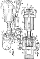
- FIG. 3 is an enlarged detail view of a GCPM 10-10C depicted in FIG. 1 and shows the GCPM arranged at its maximum gain position or low airspeed condition such as for the landing or take-off of an airplane.
- a bellcrank body 60 is fixedly pivoted at 61 to airplane structure 62.
- An upper arm of bellcrank body 60 is fixedly fastened through nuts and bolts 63 to the housing of GAAM (Gain Authority Adjust Motor) 27.
- the linear power actuator 12 has its housing connected pivotally at 72 to fixed structural support and has its piston rod end connected at pivot 71 to bellcrank body 60 for rotatable actuation thereof about its fixed point 61.
- the GAAM 27 has a drive shaft 28 connected to a drive arm 64 which forms a first link of a four-bar linkage mechanism.
- the swinging end of drive arm 64 is pivotally connected at 65 to one end of a middle link 66 which forms a second link of the four-bar linkage mechanism.
- middle link 66 is pivotally connected at 67 to one end of a link 68 which forms a third link of the four-bar linkage mechanism.
- link 68 is pivotally connected at 70 to the lower arm of bellcrank body 60.
- a fourth link of the four-bar linkage mechanism is formed by an imaginary link inte3 gral with the bellcrank body 60 and extends between pivot point 70 and drive shaft 28.
- Elevator control surface segment 11 is pivotally connected along a hinge axis 72 to horizontal stabilizer structure; and an elevator control arm 73 is pivotally connected at 74 to one end of an S-link 75.
- the other end of S-link 75 is pivotally connected at 76 to middle link 66.
- Pivot point 76 on middle link 66 through the kinematics of the four-bar linkage, approximately simulates an arc 77 produced by a radial 75 R having its center at pivot 74.
- the path of arc 77R passes directly over the structurally fixed pivot point 61 of the bell3 crank body 60.
- the radial arc 77 is not exact, geomet3 rically, but it is close enough so that there is no significant control input to the elevator control sur3 face segment 11 during a gain change of GCPM 10. This is an important aspect of the GCPM 10, because it is necessary to maintain the same pilot/copilot primary control input to the elevator control surface segment 11 without introducing a secondary control input through the kinematic motion of the four-bar linkage.
- the four-3 bar linkage essentially functions as a variable length arm of bellcrank body 60 to position pivotal attach points 76 of S-link 75, relative to the pivotal axis 61 of the bellcrank body 60, for adjusting the maximum angle-of-deflection range of the elevator control sur3 face segment 11.
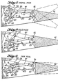
- the maximum arc-of-travel of an elevator control sur3 face, at slow landing or take-off airspeeds, is approxi3 mately plus-or-minus 30 degrees.
- the aerodynamic forces produced by the angular deflection of a control surface segment also increases; and a lesser arc-of-travel range of the control surface segment is required for control of airplane attitude.
- a main power actuator unit or rotary PA 80 has its housing fixedly mounted to a structural support beam 83 which is fastened at 84 and 85 to fixed structure.
- Rotary PA 80 has a drive shaft 81 connected to an elongated drive arm 82 at approxi3 mately mid-length thereof.
- GAAM (Gain Authority Adjust Motor) 86 has its housing fixedly mounted to one end of the elongated drive arm 82.
- the GAAM 86 has a drive shaft 87 connected to a crank arm 88 which forms a first link of four-bar linkage.
- the swinging end of crank arm 88 is pivotally connected at 89 to one end of a middle link 90 which forms a second link of the four-bar linkage.
- middle link 90 is pivotally connected at 91 to one end of a link 92 which forms a third link of the four-bar linkage.
- link 92 is pivotally connected at 93 to the other end of elongated drive arm 82.
- a fourth link of the four-bar linkage is formed by the elongated drive arm 82 and extends between pivot point 93 and drive shaft 87 of GAAM 86.
- Elevator control surface segment 94 is pivotally connected along a hinge axis 85 to horizontal stabilizer structure 83; and an elevator control arm 95 is pivot3 ally connected at 96 to one end of control rod 97. The other end of control rod 97 is pivotally connected at 98 on middle link 90. Pivot point 98 on middle link 90, through the kinematics of the four-bar linkage, approxi3 mately simulates an arc 99 produced by a radial 99R hav3 ing its center at pivot 96. The path of arc 99R passes directly over the axis of the drive shaft 81 of rotary PA 80.
- the radial arc 99 is not exact, geometrically, but it is close enough so that there is no significant control input to the elevator control surface segment 94 during a gain change of the GCPM.
- the four-bar linkage functions to position pivotal attach point 98, of con3 trol rod 97, relative to the pivotal axis 81 of the elongated drive arm 82 for adjusting the maximum angle-3 of-deflection range of the elevator control surface segment 94.
- the PA is still operated over its full stroke, but because of a change in the mechanical ratio output of the GCPM, through the kinematics of a four-bar linkage mechanism, there is an increase in the force of the control stroke output with an accompanying decrease in the length of control stroke from the GCPM.
- the PA is unaware of an increase in hinge moment due to the higher airspeed and greater aerodynamic impact pressure acting on the deflected control surface; therefore, in this situation, the GCPM functions as an impedance matching device.
- the GCPM is set at a high-gain position in order to accomplish this.
- the GCPM functions as a load impedance matching device and permits the use of a much smaller size PA than in the present known approach of designing for the maximum hinge moments encountered for both moving the control surface through its maximum angle-of-deflection range and at its predetermined maximum rate.
Landscapes
- Engineering & Computer Science (AREA)
- Aviation & Aerospace Engineering (AREA)
- Automation & Control Theory (AREA)
- Radar, Positioning & Navigation (AREA)
- Remote Sensing (AREA)
- Physics & Mathematics (AREA)
- General Physics & Mathematics (AREA)
- Safety Devices In Control Systems (AREA)
- Control Of Position, Course, Altitude, Or Attitude Of Moving Bodies (AREA)
- Feedback Control In General (AREA)
Claims (5)
Priority Applications (1)
| Application Number | Priority Date | Filing Date | Title |
|---|---|---|---|
| DE8686200408T DE3667554D1 (de) | 1986-03-14 | 1986-03-14 | System fuer luftfahrtelektroniksteuerung. |
Applications Claiming Priority (1)
| Application Number | Priority Date | Filing Date | Title |
|---|---|---|---|
| US06/519,288 US4598890A (en) | 1983-08-01 | 1983-08-01 | Avionic control system |
Publications (2)
| Publication Number | Publication Date |
|---|---|
| EP0236583A1 EP0236583A1 (de) | 1987-09-16 |
| EP0236583B1 true EP0236583B1 (de) | 1989-12-13 |
Family
ID=24067661
Family Applications (1)
| Application Number | Title | Priority Date | Filing Date |
|---|---|---|---|
| EP86200408A Expired EP0236583B1 (de) | 1983-08-01 | 1986-03-14 | System für Luftfahrtelektroniksteuerung |
Country Status (3)
| Country | Link |
|---|---|
| US (1) | US4649484A (de) |
| EP (1) | EP0236583B1 (de) |
| DE (2) | DE3613196A1 (de) |
Cited By (11)
| Publication number | Priority date | Publication date | Assignee | Title |
|---|---|---|---|---|
| US7717368B2 (en) | 2005-06-07 | 2010-05-18 | Urban Aeronautics Ltd. | Apparatus for generating horizontal forces in aerial vehicles and related method |
| US7789342B2 (en) | 2001-06-04 | 2010-09-07 | Urban Aeronautics, Ltd. | Vehicles particularly useful as VTOL vehicles |
| US7806362B2 (en) | 2005-01-10 | 2010-10-05 | Urban Aeronautics Ltd. | Ducted fan VTOL vehicles |
| US7857253B2 (en) | 2003-10-27 | 2010-12-28 | Urban Aeronautics Ltd. | Ducted fan VTOL vehicles |
| US7918416B2 (en) | 2001-05-29 | 2011-04-05 | Urban Aeronautics, Ltd. | Ducted fan vehicles particularly useful as VTOL aircraft |
| US7946528B2 (en) | 2005-04-15 | 2011-05-24 | Urban Aeronautics, Ltd. | Flight control system especially suited for VTOL vehicles |
| US8020804B2 (en) | 2006-03-01 | 2011-09-20 | Urban Aeronautics, Ltd. | Ground effect vanes arrangement |
| US8342441B2 (en) | 2008-09-02 | 2013-01-01 | Urban Aeronautics Ltd. | VTOL vehicle with coaxially tilted or tiltable rotors |
| US8496200B2 (en) | 2007-05-02 | 2013-07-30 | Urban Aeronautics Ltd. | Control flows and forces in VTOL vehicles |
| US8833692B2 (en) | 2006-11-27 | 2014-09-16 | Urban Aeronautics Ltd. | Wall effects on VTOL vehicles |
| US8876038B2 (en) | 2010-10-05 | 2014-11-04 | Urban Aeronautics Ltd. | Ducted fan for VTOL vehicles with system and method to reduce roll moments |
Families Citing this family (62)
| Publication number | Priority date | Publication date | Assignee | Title |
|---|---|---|---|---|
| FR2583017B1 (fr) * | 1985-06-07 | 1987-09-18 | Aerospatiale | Dispositif de commande pourvu de deux manches couples |
| FR2603866A1 (fr) * | 1986-09-12 | 1988-03-18 | Messerschmitt Boelkow Blohm | Systeme de commande de gouvernes de profondeur |
| US5063371A (en) * | 1986-09-29 | 1991-11-05 | Oyer Michael W | Aircraft security system |
| US4933668A (en) * | 1986-09-29 | 1990-06-12 | Shepherd Intelligence Systems, Inc. | Aircraft security system |
| US4887214A (en) * | 1987-10-27 | 1989-12-12 | The Boeing Company | Flight control system employing two dual controllers operating a dual actuator |
| FR2628858B1 (fr) * | 1988-03-15 | 1990-08-17 | Aerospatiale | Systeme de commande de vol pour aeronef |
| US4965879A (en) * | 1988-10-13 | 1990-10-23 | United Technologies Corporation | X-wing fly-by-wire vehicle management system |
| DE4029333A1 (de) * | 1990-09-15 | 1992-03-19 | Teves Gmbh Alfred | System fuer ein kraftfahrzeug in modulbauweise |
| US5274554A (en) * | 1991-02-01 | 1993-12-28 | The Boeing Company | Multiple-voting fault detection system for flight critical actuation control systems |
| DE4111023C2 (de) * | 1991-04-05 | 2003-11-20 | Bosch Gmbh Robert | Elektronisches System für ein Fahrzeug |
| US5182505A (en) * | 1991-06-19 | 1993-01-26 | Honeywell Inc. | Aircraft control surface position transducer |
| US5493497A (en) * | 1992-06-03 | 1996-02-20 | The Boeing Company | Multiaxis redundant fly-by-wire primary flight control system |
| US5377109A (en) * | 1992-07-31 | 1994-12-27 | Lear Astronics Corp. | Failsafe digital bus to analog protocol converter system |
| US5588620A (en) * | 1992-08-26 | 1996-12-31 | Gilbert; Raymond D. | Radial-force spoiler system |
| FR2709110B1 (fr) * | 1993-08-20 | 1995-11-10 | Lucas Air Equipement | Dispositif de servocommande d'un organe de commande de vol d'aéronef. |
| US5670856A (en) * | 1994-11-07 | 1997-09-23 | Alliedsignal Inc. | Fault tolerant controller arrangement for electric motor driven apparatus |
| US5615119A (en) * | 1995-06-07 | 1997-03-25 | Aurora Flight Sciences Corporation | Fault tolerant automatic control system utilizing analytic redundancy |
| US6085127A (en) * | 1997-03-18 | 2000-07-04 | Aurora Flight Sciences Corporation | Fault tolerant automatic control system utilizing analytic redundancy |
| US6539290B1 (en) | 1995-06-07 | 2003-03-25 | Dabulamanzi Holdings, Llc | Method, apparatus and design procedure for controlling multi-input, multi-output (MIMO) parameter dependent systems using feedback LTI'zation |
| DE19741869C2 (de) * | 1997-09-23 | 2000-12-07 | Daimler Chrysler Ag | Vorrichtung zur Betätigung einer elektromagnetischen Bremse eines Fahrzeuges |
| US6572055B1 (en) | 1999-08-10 | 2003-06-03 | Bombardier Aerospace Corporation | Hydrostatic sidestick coupling |
| GB2355053A (en) * | 1999-10-06 | 2001-04-11 | Marconi Electronic Syst Ltd | An articulated linkage mechanism |
| US7275712B2 (en) | 2002-05-28 | 2007-10-02 | Urban Aeronautics, Ltd. | Ducted fan vehicles particularly useful as VTOL aircraft |
| US6622972B2 (en) * | 2001-10-31 | 2003-09-23 | The Boeing Company | Method and system for in-flight fault monitoring of flight control actuators |
| AU2003269439A1 (en) * | 2002-10-01 | 2004-04-23 | Urban Aeronautics Ltd. | Flight control system for vtol aircraft |
| FR2852683B1 (fr) * | 2003-03-19 | 2005-05-20 | Airbus France | Procede et dispositif d'aide au pilotage d'un aeronef lors d'une approche de non precision pendant une phase d'atterrissage. |
| US7098619B2 (en) * | 2004-01-28 | 2006-08-29 | Stridsberg Innovation Ab | Actuator and movement linkage system |
| US7770842B2 (en) * | 2004-08-24 | 2010-08-10 | Honeywell International Inc. | Aircraft flight control surface actuation system communication architecture |
| US7439634B2 (en) * | 2004-08-24 | 2008-10-21 | Honeywell International Inc. | Electrical starting, generation, conversion and distribution system architecture for a more electric vehicle |
| US7367530B2 (en) * | 2005-06-21 | 2008-05-06 | The Boeing Company | Aerospace vehicle yaw generating systems and associated methods |
| US7549605B2 (en) * | 2005-06-27 | 2009-06-23 | Honeywell International Inc. | Electric flight control surface actuation system for aircraft flaps and slats |
| US20070007385A1 (en) * | 2005-06-27 | 2007-01-11 | Honeywell International, Inc. | Electric flight control surface actuation system electronic architecture |
| US20070093941A1 (en) * | 2005-10-21 | 2007-04-26 | Lizotte Sarah K | Electronically modeled actuator controller |
| US8346409B2 (en) | 2005-12-19 | 2013-01-01 | Vertical Power, Inc. | Variable speed flap retraction and notification |
| US7796054B2 (en) * | 2005-12-19 | 2010-09-14 | Vertical Power, Inc. | Aircraft electrical system evaluation |
| US20070142980A1 (en) * | 2005-12-19 | 2007-06-21 | Marc Ausman | Avionics method and apparatus |
| US8103393B2 (en) * | 2005-12-19 | 2012-01-24 | Vertical Power, Inc. | Aircraft exhaust gas temperature monitor |
| US8340842B2 (en) | 2005-12-19 | 2012-12-25 | Vertical Power, Inc. | Aircraft emergency handling |
| US7622818B2 (en) * | 2005-12-19 | 2009-11-24 | Vertical Power, Inc. | Backup electrical power system for solid-state aircraft power distribution systems |
| US20080237402A1 (en) * | 2005-12-19 | 2008-10-02 | Marc Ausman | Aircraft trim safety system and backup controls |
| US20090072083A1 (en) * | 2006-06-02 | 2009-03-19 | Honeywell International, Inc. | Actuation system with redundant motor actuators |
| EP2156256A2 (de) | 2007-04-05 | 2010-02-24 | Bombardier Inc. | Seriell redundantes einkanaliges mehrwege-fly-by-wire-flugsteuersystem mit mehreren achsen |
| US7973533B2 (en) | 2008-02-27 | 2011-07-05 | Vertical Power, Inc. | In-circuit testing for integrity of solid-state switches |
| DE102008022092A1 (de) * | 2008-05-05 | 2009-11-19 | Airbus Deutschland Gmbh | Fehlertolerantes Stellsystem zur Verstellung von Klappen eines Flugzeugs mit einer Verstell-Kinematik mit feststehender Drehachse |
| FR2940787A1 (fr) * | 2009-01-08 | 2010-07-09 | Airbus France | Systeme de commandes de vol plus electrique a bord d'un aeronef |
| DE102009022602A1 (de) * | 2009-05-26 | 2010-12-02 | Airbus Deutschland Gmbh | Flugzeug mit einem Hochauftriebssystem |
| US8534599B2 (en) * | 2011-03-31 | 2013-09-17 | Hamilton Sundstrand Corporation | Redundant two stage electro-hydraulic servo actuator control |
| JP5748340B2 (ja) | 2011-08-22 | 2015-07-15 | ナブテスコ株式会社 | 流体アクチュエータ |
| FR2982239B1 (fr) * | 2011-11-08 | 2014-05-09 | Airbus Operations Sas | Procede et dispositif de detection du blocage d'une gouverne d'aeronef. |
| FR3007131B1 (fr) * | 2013-06-14 | 2015-12-11 | Thales Sa | Procede et dispositif de diagnostic d'une perte de controle d'un aeronef |
| US9293993B1 (en) | 2014-01-30 | 2016-03-22 | Edvin Shehu | Multiphase buck converter controller without PID compensator or compensated error amplifier in the control loop |
| FR3020036B1 (fr) * | 2014-04-16 | 2017-11-24 | Airbus Operations Sas | Systeme d'actionneur pour gouverne d'aeronef. |
| US10538310B2 (en) | 2016-06-29 | 2020-01-21 | Parker-Hannifin Corporation | Near synchronous distributed hydraulic motor driven actuation system |
| US10444128B2 (en) * | 2016-10-10 | 2019-10-15 | The Boeing Company | Load path status detection system |
| WO2018118070A1 (en) * | 2016-12-22 | 2018-06-28 | Kitty Hawk Corporation | Distributed flight control system |
| US10543904B2 (en) * | 2017-02-17 | 2020-01-28 | Textron Innovations Inc. | System and method for flaperon and/or aileron control |
| JP6779183B2 (ja) * | 2017-07-18 | 2020-11-04 | 川崎重工業株式会社 | 電気機械式アクチュエータを備える航空機操舵システム |
| US11435761B1 (en) | 2021-07-23 | 2022-09-06 | Beta Air, Llc | System and method for distributed flight control system for an electric vehicle |
| US11407496B1 (en) | 2021-08-17 | 2022-08-09 | Beta Air, Llc | Systems and methods for redundant flight control in an aircraft |
| US11427305B1 (en) | 2021-09-16 | 2022-08-30 | Beta Air, Llc | Methods and systems for flight control for managing actuators for an electric aircraft |
| US11465734B1 (en) | 2021-09-16 | 2022-10-11 | Beta Air, Llc | Systems and methods for distrubuted flight controllers for redundancy for an electric aircraft |
| WO2025089431A2 (ko) * | 2023-10-23 | 2025-05-01 | 엘지전자 주식회사 | 신호 처리 장치 및 이를 구비하는 차량용 디스플레이 장치 |
Family Cites Families (15)
| Publication number | Priority date | Publication date | Assignee | Title |
|---|---|---|---|---|
| US2652995A (en) * | 1948-05-18 | 1953-09-22 | Saunders Roe Ltd | Flying controls for aircraft |
| US2796774A (en) * | 1952-05-03 | 1957-06-25 | North American Aviation Inc | Control system ratio shift mechanism |
| US2974908A (en) * | 1957-04-03 | 1961-03-14 | Bendix Corp | Closed loop ratio changer and automatic trim computer means for controlling the position of an aircraft control surface |
| US3618419A (en) * | 1969-09-30 | 1971-11-09 | Boeing Co | Gain control device |
| US3905241A (en) * | 1973-10-29 | 1975-09-16 | Mc Donnell Douglas Corp | Electrical primary flight control system |
| GB1502184A (en) * | 1974-07-05 | 1978-02-22 | Sperry Rand Corp | Automatic flight control systems |
| US4012014A (en) * | 1975-09-11 | 1977-03-15 | Mcdonnell Douglas Corporation | Aircraft flight controller |
| FR2344063A1 (fr) * | 1976-03-10 | 1977-10-07 | Smiths Industries Ltd | Circuit numerique de commande a deux voies au moins |
| US4105900A (en) * | 1977-02-16 | 1978-08-08 | The Boeing Company | Signal selection apparatus for redundant signal sources |
| DE2828484A1 (de) * | 1977-07-04 | 1979-01-25 | Smiths Industries Ltd | Regelsystem zum ableiten eines ausgangssignals |
| US4264827A (en) * | 1978-11-06 | 1981-04-28 | The Boeing Company | Current mode data or power bus |
| US4199663A (en) * | 1978-11-06 | 1980-04-22 | The Boeing Company | Autonomous terminal data communications system |
| US4345195A (en) * | 1979-12-13 | 1982-08-17 | Sperry Corporation | Strapdown multifunction servoactuator apparatus for aircraft |
| US4472780A (en) * | 1981-09-28 | 1984-09-18 | The Boeing Company | Fly-by-wire lateral control system |
| EP0152714B1 (de) * | 1984-01-09 | 1987-04-01 | AEROSPATIALE Société Nationale Industrielle | Flugsteuereinrichtung für Luftfahrzeuge |
-
1985
- 1985-07-12 US US06/754,330 patent/US4649484A/en not_active Expired - Lifetime
-
1986
- 1986-03-14 EP EP86200408A patent/EP0236583B1/de not_active Expired
- 1986-04-18 DE DE19863613196 patent/DE3613196A1/de not_active Withdrawn
- 1986-04-18 DE DE19863613197 patent/DE3613197A1/de not_active Withdrawn
Cited By (12)
| Publication number | Priority date | Publication date | Assignee | Title |
|---|---|---|---|---|
| US7918416B2 (en) | 2001-05-29 | 2011-04-05 | Urban Aeronautics, Ltd. | Ducted fan vehicles particularly useful as VTOL aircraft |
| US7789342B2 (en) | 2001-06-04 | 2010-09-07 | Urban Aeronautics, Ltd. | Vehicles particularly useful as VTOL vehicles |
| US7857253B2 (en) | 2003-10-27 | 2010-12-28 | Urban Aeronautics Ltd. | Ducted fan VTOL vehicles |
| US8622335B2 (en) | 2003-10-27 | 2014-01-07 | Urban Aeronautics, Ltd. | Ducted fan VTOL vehicles |
| US7806362B2 (en) | 2005-01-10 | 2010-10-05 | Urban Aeronautics Ltd. | Ducted fan VTOL vehicles |
| US7946528B2 (en) | 2005-04-15 | 2011-05-24 | Urban Aeronautics, Ltd. | Flight control system especially suited for VTOL vehicles |
| US7717368B2 (en) | 2005-06-07 | 2010-05-18 | Urban Aeronautics Ltd. | Apparatus for generating horizontal forces in aerial vehicles and related method |
| US8020804B2 (en) | 2006-03-01 | 2011-09-20 | Urban Aeronautics, Ltd. | Ground effect vanes arrangement |
| US8833692B2 (en) | 2006-11-27 | 2014-09-16 | Urban Aeronautics Ltd. | Wall effects on VTOL vehicles |
| US8496200B2 (en) | 2007-05-02 | 2013-07-30 | Urban Aeronautics Ltd. | Control flows and forces in VTOL vehicles |
| US8342441B2 (en) | 2008-09-02 | 2013-01-01 | Urban Aeronautics Ltd. | VTOL vehicle with coaxially tilted or tiltable rotors |
| US8876038B2 (en) | 2010-10-05 | 2014-11-04 | Urban Aeronautics Ltd. | Ducted fan for VTOL vehicles with system and method to reduce roll moments |
Also Published As
| Publication number | Publication date |
|---|---|
| DE3613197A1 (de) | 1987-10-22 |
| DE3613196A1 (de) | 1987-10-22 |
| US4649484A (en) | 1987-03-10 |
| EP0236583A1 (de) | 1987-09-16 |
Similar Documents
| Publication | Publication Date | Title |
|---|---|---|
| EP0236583B1 (de) | System für Luftfahrtelektroniksteuerung | |
| US4598890A (en) | Avionic control system | |
| JP3384833B2 (ja) | 航空機のためのフライバイワイヤーフライトコントロールシステムおよび航空機上の複数個の飛行制御翼面の位置を制御する方法 | |
| US4765568A (en) | Method and system for controlling the elevator assemblies of an aircraft | |
| US4759515A (en) | Drive control for a vertical rudder of an aircraft | |
| AU2010309603B2 (en) | Tactile cueing apparatus | |
| EP1301835B1 (de) | Flugsteuereinheit mit integrierter spoilerantriebsteuerelektronik | |
| WO2002006115A9 (en) | Flight control modules merged into the integrated modular avionics | |
| EP2311729A1 (de) | Taktile Signalisierungsvorrichtung | |
| US6644600B1 (en) | Method and system for providing manipulation restraining forces for a stick controller on an aircraft | |
| EP3456626B1 (de) | Elektrische pedalsteuerungsvorrichtung für flugzeuge | |
| US20070271008A1 (en) | Manual and computerized flight control system with natural feedback | |
| EP0237650B1 (de) | Flugregelsystem | |
| US3940094A (en) | Wing sweep control system | |
| US20260021884A1 (en) | Electronic unit for a tactile cueing apparatus | |
| JPS6215200A (ja) | 航空電子制御システム | |
| US20240409203A1 (en) | Hybrid Flight Control System | |
| US12491990B2 (en) | Fly-by-wire system with FCC-integrated servo actuators | |
| EP4306431A1 (de) | Elektronische einheit für ein taktiles hinweisgerät | |
| MacManus | V-22 tiltrotor fly-by-wire flight control system | |
| US3586264A (en) | High resolution control system | |
| JPS62214099A (ja) | 航空電子制御システム | |
| BATEMAN | System design trends in commercial transport aircraft evolution or revolution? | |
| GB2620633A (en) | An electronic unit for a tactile cueing apparatus | |
| Heimbold | Applications of advanced electric/electronic technology to conventional aircraft |
Legal Events
| Date | Code | Title | Description |
|---|---|---|---|
| PUAI | Public reference made under article 153(3) epc to a published international application that has entered the european phase |
Free format text: ORIGINAL CODE: 0009012 |
|
| AK | Designated contracting states |
Kind code of ref document: A1 Designated state(s): DE FR GB IT NL |
|
| 17P | Request for examination filed |
Effective date: 19870928 |
|
| 17Q | First examination report despatched |
Effective date: 19890207 |
|
| ITF | It: translation for a ep patent filed | ||
| GRAA | (expected) grant |
Free format text: ORIGINAL CODE: 0009210 |
|
| AK | Designated contracting states |
Kind code of ref document: B1 Designated state(s): DE FR GB IT NL |
|
| ET | Fr: translation filed | ||
| REF | Corresponds to: |
Ref document number: 3667554 Country of ref document: DE Date of ref document: 19900118 |
|
| PLBE | No opposition filed within time limit |
Free format text: ORIGINAL CODE: 0009261 |
|
| STAA | Information on the status of an ep patent application or granted ep patent |
Free format text: STATUS: NO OPPOSITION FILED WITHIN TIME LIMIT |
|
| 26N | No opposition filed | ||
| PGFP | Annual fee paid to national office [announced via postgrant information from national office to epo] |
Ref country code: DE Payment date: 19920227 Year of fee payment: 7 |
|
| PGFP | Annual fee paid to national office [announced via postgrant information from national office to epo] |
Ref country code: GB Payment date: 19920309 Year of fee payment: 7 |
|
| ITTA | It: last paid annual fee | ||
| PGFP | Annual fee paid to national office [announced via postgrant information from national office to epo] |
Ref country code: NL Payment date: 19920331 Year of fee payment: 7 |
|
| PG25 | Lapsed in a contracting state [announced via postgrant information from national office to epo] |
Ref country code: GB Effective date: 19930314 |
|
| PGFP | Annual fee paid to national office [announced via postgrant information from national office to epo] |
Ref country code: FR Payment date: 19930330 Year of fee payment: 8 |
|
| PG25 | Lapsed in a contracting state [announced via postgrant information from national office to epo] |
Ref country code: NL Effective date: 19931001 |
|
| GBPC | Gb: european patent ceased through non-payment of renewal fee |
Effective date: 19930314 |
|
| NLV4 | Nl: lapsed or anulled due to non-payment of the annual fee | ||
| PG25 | Lapsed in a contracting state [announced via postgrant information from national office to epo] |
Ref country code: DE Effective date: 19931201 |
|
| PG25 | Lapsed in a contracting state [announced via postgrant information from national office to epo] |
Ref country code: FR Effective date: 19941130 |
|
| REG | Reference to a national code |
Ref country code: FR Ref legal event code: ST |
|
| PG25 | Lapsed in a contracting state [announced via postgrant information from national office to epo] |
Ref country code: IT Free format text: LAPSE BECAUSE OF NON-PAYMENT OF DUE FEES;WARNING: LAPSES OF ITALIAN PATENTS WITH EFFECTIVE DATE BEFORE 2007 MAY HAVE OCCURRED AT ANY TIME BEFORE 2007. THE CORRECT EFFECTIVE DATE MAY BE DIFFERENT FROM THE ONE RECORDED. Effective date: 20050314 |