EP0235472B1 - Thermostatic mixing valves for the fluid-cooling circuits of internal-combustion engines - Google Patents
Thermostatic mixing valves for the fluid-cooling circuits of internal-combustion engines Download PDFInfo
- Publication number
- EP0235472B1 EP0235472B1 EP86402395A EP86402395A EP0235472B1 EP 0235472 B1 EP0235472 B1 EP 0235472B1 EP 86402395 A EP86402395 A EP 86402395A EP 86402395 A EP86402395 A EP 86402395A EP 0235472 B1 EP0235472 B1 EP 0235472B1
- Authority
- EP
- European Patent Office
- Prior art keywords
- valve
- mixing valve
- capsule element
- piston
- wax capsule
- Prior art date
- Legal status (The legal status is an assumption and is not a legal conclusion. Google has not performed a legal analysis and makes no representation as to the accuracy of the status listed.)
- Expired - Lifetime
Links
Images

Classifications
-
- F—MECHANICAL ENGINEERING; LIGHTING; HEATING; WEAPONS; BLASTING
- F01—MACHINES OR ENGINES IN GENERAL; ENGINE PLANTS IN GENERAL; STEAM ENGINES
- F01P—COOLING OF MACHINES OR ENGINES IN GENERAL; COOLING OF INTERNAL-COMBUSTION ENGINES
- F01P7/00—Controlling of coolant flow
- F01P7/14—Controlling of coolant flow the coolant being liquid
- F01P7/16—Controlling of coolant flow the coolant being liquid by thermostatic control
- F01P7/167—Controlling of coolant flow the coolant being liquid by thermostatic control by adjusting the pre-set temperature according to engine parameters, e.g. engine load, engine speed
-
- G—PHYSICS
- G05—CONTROLLING; REGULATING
- G05D—SYSTEMS FOR CONTROLLING OR REGULATING NON-ELECTRIC VARIABLES
- G05D23/00—Control of temperature
- G05D23/01—Control of temperature without auxiliary power
- G05D23/13—Control of temperature without auxiliary power by varying the mixing ratio of two fluids having different temperatures
- G05D23/1306—Control of temperature without auxiliary power by varying the mixing ratio of two fluids having different temperatures for liquids
- G05D23/132—Control of temperature without auxiliary power by varying the mixing ratio of two fluids having different temperatures for liquids with temperature sensing element
- G05D23/1333—Control of temperature without auxiliary power by varying the mixing ratio of two fluids having different temperatures for liquids with temperature sensing element measuring the temperature of incoming fluid
-
- F—MECHANICAL ENGINEERING; LIGHTING; HEATING; WEAPONS; BLASTING
- F01—MACHINES OR ENGINES IN GENERAL; ENGINE PLANTS IN GENERAL; STEAM ENGINES
- F01P—COOLING OF MACHINES OR ENGINES IN GENERAL; COOLING OF INTERNAL-COMBUSTION ENGINES
- F01P2070/00—Details
- F01P2070/04—Details using electrical heating elements
Definitions
- the invention relates to a thermostatic mixing valve for liquid cooling circuits of internal combustion engines equipped with a cooling radiator and a circulation pump, which valve is intended to be mounted on a bypass, established between the pipe. of the circuit leading to the radiator the hot coolant which leaves the engine and the pipe bringing back to the engine the cool coolant which leaves the radiator, which mixing valve is arranged so as to form a lukewarm liquid by mixing variable proportions of the above liquid hot and cold liquid coming out of the radiator, which valve comprises an expandable wax capsule, of known type, with housing and piston, which is sensitive to the temperature of this lukewarm liquid and which determines said proportions, which valve comprises a body cylindrical hollow on at least an inner part of its length and a drawer comprising a clo perforated transverse ison, displaceable in translation parallel to a translation axis coinciding with the axis of the cylindrical part by the aforesaid wax capsule against the action of a spring and arranged inside the body in the cylindrical part to close all the more a hot
- a mixing valve of the type defined in the preamble is described in FR-A.2.254.717.
- the casing of the wax capsule is fixed to a transverse partition integral with the valve body and the piston of the wax capsule acts directly on the drawer, the above spring being interposed between the drawer and the said transverse wall. which is part of a removable cover. Due to the position of the housing and the piston of the wax capsule with respect to the removable transverse wall and the spring, it is only possible to modify the setting of such a valve by removing the above-mentioned cover in order to be able to replace the spring with a spring of different characteristics or to modify the calibration of this spring by inserting a shim of calibrated thickness.
- the object of the invention is to make these valves shabby such that their action can be easily adjusted, preferably during operation.
- the mixing valve according to the invention is essentially characterized in that the piston of the wax capsule bears on the aforesaid transverse wall of the valve body, towards which it is biased by the spring, and in that the housing of the wax capsule is fixed coaxially to the drawer and rigidly on the partition, so that the housing and the drawer move together under the action of the dilation of the capsule.
- FR-A-2,434,723 describes a thermostatic mixing valve associated with a liquid cooling circuit of internal combustion engines but arranged so as to maintain at a set value the temperature of the passenger compartment of the vehicle driven by this engine, this passenger compartment being heated by air discharged through an exchanger which is supplied with liquid taken from the above-mentioned cooling circuit.
- the drawer is only able to move between two stops and there is therefore provided a spring connection between the capsule housing and the drawer.
- the outlet orifice is located laterally with respect to the valve body.
- the mixing valve according to the invention comprises means for adjusting in operation, relative to the valve body, the position of the piston of the wax capsule according to external parameters, these adjustment means advantageously comprising, and in known manner (see FR-A-2,434,723), a second wax capsule, situated outside the valve body, the temperature of which depends on at least one of these external parameters.
- these adjustment means advantageously comprising, and in known manner (see FR-A-2,434,723), a second wax capsule, situated outside the valve body, the temperature of which depends on at least one of these external parameters.
- the housing of the second wax capsule is secured to the removable wall and that the piston of this second wax capsule passes through the removable wall with the interposition of sealing means so as to axially touch the piston of the first wax capsule.
- This set of features simplifies manufacturing, facilitates the flow of liquid through the mixing valve and allows the first wax capsule to accurately assess the temperature of lukewarm water.
- Figure 1 shows schematically an internal combustion engine whose cooling circuit is equipped with a mixing valve according to this preferred embodiment.
- Figure 2 shows the mixing valve of Figure 1, in longitudinal section on a larger scale.
- Figure 3 is a section of the mixing valve along line III-III of Figure 2.
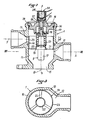
- the invention relates to a thermostatic mixing valve 1 (the dimensions of which have been exaggerated in this figure) for the liquid cooling circuit of an internal combustion engine 2, this circuit being equipped a cooling radiator 3 and a circulation pump 4.
- the mixing valve 1 is mounted on a bypass 5 established between the pipe 6 of the circuit leading to the radiator 3 the hot coolant which leaves the engine 2 and the pipe 7, 8 bringing back to the engine 2 the cold coolant which leaves the radiator 3.
- the circulation pump 4 is mounted on the part 8 of the return pipe 7, 8 which is located downstream of the mixing valve 1.
- This ci is arranged so as to form, by mixing variable proportions of hot liquid (arriving via the bypass 5) and cold liquid (arriving via the pipe part 7), a lukewarm liquid which is then introduced into the motor 2 (via the pipe element 8) .
- the valve 1 comprises a thermostatic member 9 (FIG. 2), sensitive to the temperature of the warm liquid, which determines the respective proportions of hot liquid and cold liquid in the outgoing mixture or warm liquid.
- the valve 1 comprises a body 10 provided with an internally cylindrical part 11 into which the hot liquid and the cold liquid arrive, respectively through orifices 12 and 13 which are offset parallel to the axis XX of this cylindrical part 11.
- the body 10 can have either (as shown) a single orifice 12 for the arrival of the hot liquid, or several orifices 12 opening out in the same transverse plane, that is to say a plane perpendicular to axis XX.
- it can have either (as shown) a single orifice 13 for the arrival of the cold liquid, or several orifices 13 opening out in the same transverse plane.
- the body 10 of the valve 1 is further provided with an outlet orifice 15, for lukewarm liquid, at that of its axial ends which is the farthest from the inlet orifice 13 of the cold liquid, that is ie at its lower end according to FIG. 2, and it is closed at its opposite axial end by a removable transverse wall 16 serving as a support for the thermostatic member 9.
- the thermostatic member 9 consists of a wax capsule, the housing 17 of which is fixed to a perforated transverse partition 18 of the drawer 14, with a large transverse clearance inside the cylindrical part 11 of the body 10 and coaxially with this part. 11, so as to project from the side of the outlet orifice 15.
- the piston 19 of the wax capsule is supported on the transverse wall 16 of the body 10 towards which it is biased by a spring 20.
- the partition transverse 18, which may simply consist of radial arms 21 joining a central fixing hub 22 (for fixing the housing 17) to a cylindrical skirt 23, is made in one piece with the drawer 14 and is placed at that axial ends of the drawer 14 which is closest to the outlet orifice 15.
- An annular seal 34 mounted in a groove formed in the cylindrical part 11 between the orifices 12 and 13, cooperates with the skirt 23 d u drawer 14 to prevent leaks from occurring along the outer surface of the skirt 23.
- a mixing valve is thus obtained, the operation of which is as follows.
- the liquid known as "hot” normally arriving from the engine 2 via the pipe 5 to the orifice 12 of the valve 1 is in fact at ambient temperature, that is to say that its temperature is relatively low.
- the thermostatic member 9 is contracted and the slide 14 occupies, under the effect of the spring 20, its highest position, as shown in FIG. 2.
- the orifice 13 is therefore closed by the skirt 23, which prevents water from circulating in the radiator 3.
- the orifice 12 is opened wide and the coolant, circulated by the pump 4, rotates between the engine 2 and the valve 1 by passing through pipes 4 and 5 and bypassing the radiator 3.
- the transverse wall 16 of the body offers a fixed support for the thermostatic member 9.
- Such means are then advantageously constituted by a second wax capsule 24 mounted outside the body 10 and sensitive to the outside temperature or to the temperature prevailing under the engine hood 2.
- the housing this wax capsule 24 can be fixed directly to the transverse wall 16 of the body 10 so that its piston 25 passes through this wall 16 inside a guide 26, the seal with the outside being ensured by an annular seal 27 which cooperates with the outer surface of this guide 26.
- the outer wax capsule 24 could also be fixed at a distance from this wall 16. In this case, it would suffice to place, between the pistons 19 and 25, a transmission rod (not shown) passing through the transverse wall 16 as shown for the piston 25 in FIG. 2.
- the mixing valve 1 according to the invention in a single version, could adapt by itself to the temperature conditions which are defined, in the technical specifications of certain automobile manufacturers, as conditions “arctic”, “temperate” and “tropical”.
- the outer wax capsule 24 could be made sensitive to at least one operating parameter other than the temperature of the atmosphere in which it is placed (for example, another temperature, atmospheric pressure, etc.) by virtue of the presence of an electrical resistance 28 surrounding the casing of the wax capsule 24, or coated with a refractory material and embedded in the wax contained in this casing.
- the supply of this electrical resistance 28 by automatic means (microprocessors, in particular) or manual, depending on one or more operating parameters, then allows the operation of the mixing valve to be controlled by this or these parameters.
- the manufacture of the body 10 by molding, the mounting of the drawer 14 and of the elements associated with it and the adaptation of the mixing valve to the various variants mentioned above by way of example are facilitated by the constitution of the transverse wall. 16 by a separate piece and fixed to the body 10, for example by means of a crimping flange 29, with the interposition of a seal 30.
- the construction of the mixing valve according to the invention from a drawer, means that it is practically balanced in pressure, whatever the pressures at the orifices 12 and 13 of arrival of hot and cold liquid, contrary to the constructions of FR-A-2,434,723 and 1,472,712.
- the electrical resistance 28 can be a positive temperature coefficient thermistor (PTC).
- PTC positive temperature coefficient thermistor
- the parameters which influence the supply of the electrical resistance 28 can be, for example, at least one of the following: outside air temperature, temperature prevailing under the engine hood, atmospheric pressure, engine load, etc. ... and have an all or nothing action or a proportional action.
Description
L' invention concerne une vanne mitigeuse thermostatique, pour circuits de refroidissenent à liquide de moteurs à combustion interne equipés d'un radiateur de refroidisenent et d'une pompe de circulation, laquelle vanne est destinée à être montée sur une dérivation, établie entre la canalisation du circuit conduisant au radiateur le liquide de refroidissement chaud qui sort du moteur et la canalisation ramenant au moteur le liquide de refroidissement froid qui sort du radiateur, laquelle vanne mitigeuse est agencée de façon à former un liquide tiède par mélange de proportions variables du susdit liquide chaud et du liquide froid qui sort du radiateur, laquelle vanne comporte une capsule à cire dilatable, de type connu, à boîtier et à piston, qui est sensible à la température de ce liquide tiède et qui détermine lesdites proportions, laquelle vanne comporte un corps creux cylindrique sur au moins une partie intérieure de sa longueur et un tiroir comportant une cloison transversale ajourée, déplaçable en translation parallèlement à un axe de translation coîncidant avec l'axe de la partie cylindrique par la susdite capsule à cire contre l'action d'un ressort et disposé à l'intérieur du corps dans la partie cylindrique de façon à fermer d'autant plus un orifice d'arrivée du liquide chaud et à ouvrir simultanément d'autant plus un orifice d'arrivée du liquide froid que la température du liquide tiède augmente, et vice versa, lesdits orifices étant ménagés dans le corps creux en y étant décalés parallèlement à l'axe de translation qui coïncide avec l'axe d'action de la capsule à cire, le corps étant obturé, à l'une de ses extrémités axiales, par une paroi transversale fixe mais démontable, et l'orifice de sortie étant situé à l'extrémité opposée du corps selon l'axe de la partie cylindrique.The invention relates to a thermostatic mixing valve for liquid cooling circuits of internal combustion engines equipped with a cooling radiator and a circulation pump, which valve is intended to be mounted on a bypass, established between the pipe. of the circuit leading to the radiator the hot coolant which leaves the engine and the pipe bringing back to the engine the cool coolant which leaves the radiator, which mixing valve is arranged so as to form a lukewarm liquid by mixing variable proportions of the above liquid hot and cold liquid coming out of the radiator, which valve comprises an expandable wax capsule, of known type, with housing and piston, which is sensitive to the temperature of this lukewarm liquid and which determines said proportions, which valve comprises a body cylindrical hollow on at least an inner part of its length and a drawer comprising a clo perforated transverse ison, displaceable in translation parallel to a translation axis coinciding with the axis of the cylindrical part by the aforesaid wax capsule against the action of a spring and arranged inside the body in the cylindrical part to close all the more a hot liquid inlet orifice and to simultaneously open all the more a cold liquid inlet orifice as the temperature of the warm liquid increases, and vice versa, said orifices being formed in the hollow body by being offset therein parallel to the axis of translation which coincides with the axis of action of the wax capsule, the body being closed, at one of its axial ends, by a fixed but removable transverse wall, and l the outlet orifice being situated at the opposite end of the body along the axis of the cylindrical part.
C'est pour simplifier la terminologie qu'on utilise ici, pour désigner le même liquide dans des parties différentes du circuit de refroidissement, les expressions "liquide chaud", "liquide tiède" et "liquide froid", étant donné qu'elles reflètent bien les niveaux respectifs de temperature au cours du fonctionnement normal du moteur. Toutefois, on ne doit pas attacher à ces expressions un sens littéral car il existe par exemple des situations dans lesquelles les trois liquides sont à une même température (moteur arrêté depuis quelque temps) ou dans lesquelles le liquide dit "chaud" est à une température relativement basse (démarrage du moteur).It is to simplify the terminology used here, to designate the same liquid in different parts of the cooling circuit, the expressions "hot liquid", "lukewarm liquid" and "cold liquid", since they reflect the respective temperature levels during normal engine operation. However, we should not attach a literal meaning to these expressions because there are, for example, situations in which the three liquids are at the same temperature (engine stopped for some time) or in which the so-called "hot" liquid is at a temperature relatively low (engine start).
Une vanne mitigeuse du type défini en préambule est décrite dans le FR-A.2.254.717. Selon ce document, le boîtier de la capsule à cire est fixé sur une cloison transversale solidaire du corps de la vanne et le piston de la capsule à cire agit directement sur le tiroir, le susdit ressort étant interposé entre le tiroir et la susdite paroi transversale qui fait partie d'un couvercle démontable. En raison de la position du boîtier et du piston de la capsule à cire par rapport à la paroi transversale démontable et au ressort, il n'est possible de modifier le réglage d'une telle vanne qu'en enlevant le susdit couvercle afin de pouvoir remplacer le ressort par un ressort de caractéristiques différentes ou pour modifier le tarage de ce ressort par insertion d'une cale d'épaisseur calibrée.A mixing valve of the type defined in the preamble is described in FR-A.2.254.717. According to this document, the casing of the wax capsule is fixed to a transverse partition integral with the valve body and the piston of the wax capsule acts directly on the drawer, the above spring being interposed between the drawer and the said transverse wall. which is part of a removable cover. Due to the position of the housing and the piston of the wax capsule with respect to the removable transverse wall and the spring, it is only possible to modify the setting of such a valve by removing the above-mentioned cover in order to be able to replace the spring with a spring of different characteristics or to modify the calibration of this spring by inserting a shim of calibrated thickness.
L'invention a pour but de rendre ces vannes mitieuses telles que l'on puisse régler aisément leur action, de préférence en cours de fonctionnement.The object of the invention is to make these valves shabby such that their action can be easily adjusted, preferably during operation.
A cet effet, la vanne mitigeuse conforme à l'invention est essentiellement caractérisée en ce que le piston de la capsule à cire prend appui sur la susdite paroi transversale du corps de vanne, vers laquelle il est sollicité par le ressort, et en ce que le boîtier de la capsule à cire est fixé coaxialement au tiroir et rigidement sur la cloison, de telle façon que le boîtier et le tiroir se déplacent ensemble sous l'action de la dilatation de la capsule.To this end, the mixing valve according to the invention is essentially characterized in that the piston of the wax capsule bears on the aforesaid transverse wall of the valve body, towards which it is biased by the spring, and in that the housing of the wax capsule is fixed coaxially to the drawer and rigidly on the partition, so that the housing and the drawer move together under the action of the dilation of the capsule.
De cette manière, il est possible de régler l'action de la vanne mitigeuse en agissant sur l'extrémité du piston, par exemple après avoir enlevé le couvercle démontable.In this way, it is possible to adjust the action of the mixing valve by acting on the end of the piston, for example after removing the removable cover.
II est à noter que le FR-A-2.434.723 décrit une vanne mitigeuse thermostatique associée à un circuit de refroidissement à liquide de moteurs à combustion interne mais agencée de façon à maintenir à une valeur de consigne la température de l'habitacle du véhicule mû par ce moteur, cet habitacle étant chauffé par de l'air refoulé à travers un échangeur qui est alimenté par du liquide prélevé sur le susdit circuit de refroidissement. Dans ce cas, le tiroir n'est capable de se déplacer qu'entre deux butées et il est donc prévu une liaison à ressort entre le boîtier de la capsule et le tiroir. Par ailleurs, l'orifice de sortie est situé latéralement par rapport au corps de la vanne.It should be noted that FR-A-2,434,723 describes a thermostatic mixing valve associated with a liquid cooling circuit of internal combustion engines but arranged so as to maintain at a set value the temperature of the passenger compartment of the vehicle driven by this engine, this passenger compartment being heated by air discharged through an exchanger which is supplied with liquid taken from the above-mentioned cooling circuit. In this case, the drawer is only able to move between two stops and there is therefore provided a spring connection between the capsule housing and the drawer. Furthermore, the outlet orifice is located laterally with respect to the valve body.
De préférence, la vanne mitigeuse conforme à l'invention comprend des moyens pour régler en fonctionnement, par rapport au corps de vanne, la position du piston de la capsule à cire en fonction de paramétres extérieurs, ces moyens de réglage comprenant avantageusement, et de façon en soi connue (voir le FR-A-2.434.723), une deuxième capsule à cire, située à l'extérieur du corps de vanne, dont la température dépend d'au moins l'un de ces paramètres extérieurs. Dans ce dernier cas, il est judicieux que le boîtier de la deuxième capsule à cire soit solidaire de la paroi démontable et que le piston de cette deuxième capsule à cire traverse la paroi démontable avec interposition de moyens d'étanchéité de façon à toucher axialement le piston de la première capsule à cire.Preferably, the mixing valve according to the invention comprises means for adjusting in operation, relative to the valve body, the position of the piston of the wax capsule according to external parameters, these adjustment means advantageously comprising, and in known manner (see FR-A-2,434,723), a second wax capsule, situated outside the valve body, the temperature of which depends on at least one of these external parameters. In the latter case, it is advisable that the housing of the second wax capsule is secured to the removable wall and that the piston of this second wax capsule passes through the removable wall with the interposition of sealing means so as to axially touch the piston of the first wax capsule.
Cet ensemble de caractéristiques simplifie la fabrication, facilite l'écoulement du liquide dans la vanne mitigeuse et permet à la première capsule à cire d'évaluer avec précision la température de l'eau tiède.This set of features simplifies manufacturing, facilitates the flow of liquid through the mixing valve and allows the first wax capsule to accurately assess the temperature of lukewarm water.
L'invention va être expliquée plus en détail à l'aide du dessin annexé qui en illustre un mode de réalisation préféré.The invention will be explained in more detail using the appended drawing which illustrates a preferred embodiment.
La figure 1 représente schématiquement un moteur à combustion interne dont le circuit de refroidissement est équipé d'une vanne mitigeuse conforme à ce mode de réalisation préféré.Figure 1 shows schematically an internal combustion engine whose cooling circuit is equipped with a mixing valve according to this preferred embodiment.
La figure 2 représente la vanne mitigeuse de la figure 1, en coupe longitudinale à plus grande échelle.Figure 2 shows the mixing valve of Figure 1, in longitudinal section on a larger scale.
La figure 3 est une coupe de la vanne mitigeuse selon la ligne III-III de la figure 2.Figure 3 is a section of the mixing valve along line III-III of Figure 2.
Ainsi qu'il ressort de la figure 1, l'invention concerne une vanne mitigeuse thermostatique 1 (dont les dimensions ont été exagérées sur cette figure) pour le circuit de refroidissement à liquide d'un moteur à combustion interne 2, ce circuit étant équipé d'un radiateur de refroidissement 3 et d'une pompe de circulation 4. La vanne mitigeuse 1 est montée sur une dérivation 5 établie entre la canalisation 6 du circuit conduisant au radiateur 3 le liquide de refroidissement chaud qui sort du moteur 2 et la canalisation 7, 8 ramenant au moteur 2 le liquide de refroidissement froid qui sort du radiateur 3. La pompe de circulation 4 est montée sur la partie 8 de la canalisation de retour 7, 8 qui est située en aval de la vanne mitigeuse 1. Celle-ci est agencée de façon à former, par mélange de proportions variables de liquide chaud (arrivant par la dérivation 5) et de liquide froid (arrivant par la partie de canalisation 7), un liquide tiède qui est ensuite introduit dans le moteur 2 (par l'intermédiaire de l'élément de canalisation 8). La vanne 1 comporte un organe thermostatique 9 (figure 2), sensible à la température du liquide tiède, qui détermine les proportions respectives de liquide chaud et de liquide froid dans le mélange sortant ou liquide tiède.As is clear from FIG. 1, the invention relates to a thermostatic mixing valve 1 (the dimensions of which have been exaggerated in this figure) for the liquid cooling circuit of an
Comme montré aux figures 1 et 2, la vanne 1 comporte un corps 10 muni d'une partie intérieurement cylindrique 11 dans laquelle arrivent le liquide chaud et le liquide froid, respectivement par des orifices 12 et 13 qui sont décalés parallèlement à l'axe X-X de cette partie cylindrique 11. Le corps 10 peut posséder soit (comme représenté) un seul orifice 12 pour l'arrivée du liquide chaud, soit plusieurs orifices 12 débouchant dans un même plan transversal, c'est-à-dire un plan perpendiculaire à l'axe X-X. De même, il peut posséder soit (comme représenté) un seul orifice 13 pour l'arrivée du liquide froid, soit plusieurs orifices 13 débouchant dans un même plan transversal.As shown in Figures 1 and 2, the valve 1 comprises a
Un tiroir cylindrique 14, mobile en translation selon l'axe X-X et actionné par l'organe thermostatique 9, est disposé à l'intérieur de la partie cylindrique 11 de façon à fermer d'autant plus le ou les orifices d'arrivée de liquide chaud 12 et à ouvrir d'autant plus le ou les orifices d'arrivée de liquide froid 13 que la température du liquide tiède augmente, et vice versa.A
Le corps 10 de la vanne 1 est en outre muni d'un orifice de sortie 15, pour le liquide tiède, à celle de ses extrémités axiales qui est la plus éloignée de l'orifice d'entrée 13 du liquide froid, c'est-à-dire à son extrémité inférieure selon la figure 2, et il est obturé, à son extrémité axiale opposée, par une paroi transversale 16 démontable servant d'appui à l'organe thermostatique 9.The
L'organe thermostatique 9 est constitué par une capsule à cire dont le boîtier 17 est fixé sur une cloison transversale ajourée 18 du tiroir 14, avec un jeu transversal important à l'intérieur de la partie cylindrique 11 du corps 10 et coaxialement à cette partie 11, de façon à faire saillie du côté de l'orifice de sortie 15. En outre, le piston 19 de la capsule à cire prend appui sur la paroi transversale 16 du corps 10 vers laquelle il est sollicité par un ressort 20. La cloison transversale 18, qui peut être simplement constituée par des bras radiaux 21 réunissant un moyeu de fixation central 22 (pour la fixation du boîtier 17) à une jupe cylindrique 23, est faite d'une seule pièce avec le tiroir 14 et est placée à celle des extrémités axiales du tiroir 14 qui est la plus proche de l'orifice de sortie 15. Un joint d'étanchéité annulaire 34, monté dans une gorge ménagée dans la partie cylindrique 11 entre les orifices 12 et 13, coopère avec la jupe 23 du tiroir 14 pour empêcher des fuites de se produire le long de la surface extérieure de la jupe 23.The thermostatic member 9 consists of a wax capsule, the
On obtient ainsi une vanne mitigeuse dont le fonctionnement est le suivant. Lorsque le moteur 2 est froid, le liquide dit "chaud" arrivant normalement du moteur 2 par la canalisation 5 à l'orifice 12 de la vanne 1 est en fait à la température ambiante, c'est-à-dire que sa température est relativement basse. De ce fait, l'organe thermostatique 9 est contracté et le tiroir 14 occupe, sous l'effet du ressort 20, sa position la plus haute, telle qu'elle est représentée à la figure 2. L'orifice 13 est donc fermé par la jupe 23, ce qui empêche l'eau de circuler dans le radiateur 3. En revanche, l'orifice 12 est ouvert en grand et le liquide de refroidissement, mis en circulation par la pompe 4, tourne entre le moteur 2 et la vanne 1 en passant par les canalisations 4 et 5 et en court-circuitant le radiateur 3.A mixing valve is thus obtained, the operation of which is as follows. When the
Lorsqu'on lance le moteur et qu'on le fait tourner suffisamment longtemps, l'eau arrivant par l'orifice 12 se réchauffe progressivement en faisant se dilater l'organe thermostatique 9. Ceci provoque la descente du tiroir 14 (selon la figure 2) et par conséquent la fermeture progesssive de l'orifice 12 et l'ouverture progressive de l'orifice 13 par la jupe 23. Une proportion de plus en plus grande de l'eau froide venant du radiateur 3 par la canalisation 7 est ainsi admise par l'orifice 13, passe à l'intérieur de la jupe 23, puis entre les bras radiaux 21, et se mélange à l'eau chaude arrivant par l'orifice 12. L'eau chaude et l'eau froide se mélangent au niveau de l'organe thermostatique 9 qui produit ainsi une régulation automatique de la température de l'eau renvoyée au moteur 2 par la pompe 4.When you start the engine and run it long enough, the water coming in through the
Dans ce qui précède, on a supposé que la paroi transversale 16 du corps offrait un appui fixe à l'organe thermostatique 9. En variante, il est possible de prévoir des moyens pour régler, par rapport au corps 10, la position de l'organe thermostatique 9 et en particulier, lorsqu'il s'agit d'une capsule à cire, du piston 19 de cette capsule, en fonction de paramètres extérieurs.In the foregoing, it has been assumed that the
De tels moyens sont alors avantageusement constitués par une deuxième capsule à cire 24 montée à l'extérieur du corps 10 et sensible à la température extérieure ou à la température régnant sous le capot du moteur 2. Comme montré à la figure 1, le boîtier de cette capsule à cire 24 peut être fixé directement à la paroi transversale 16 du corps 10 de façon que son piston 25 traverse cette paroi 16 à l'intérieur d'un guide 26, l'étanchéité avec l'extérieur étant assurée par un joint annulaire 27 qui coopère avec la surface extérieure de ce guide 26. Plus la température évaluée par la capsule à cire 24 augmente, plus son piston 25 descend (selon la figure 2) et repousse donc le piston 19 de la capsule à cire intérieure 9, ce qui décale la plage de fonctionnement de la vanne mitigeuse 1 en fonction de ladite température.Such means are then advantageously constituted by a
Au lieu d'être fixée à la paroi transversale 16 du corps 10, la capsule à cire extérieure 24 pourrait aussi être fixée à distance de cette paroi 16. Dans ce cas, il suffirait de placer, entre les pistons 19 et 25, une tige de transmission (non représentée) traversant la paroi transversale 16 comme on l'a représenté pour le piston 25 à la figure 2.Instead of being fixed to the
Dans les deux cas, la vanne mitigeuse 1 conforme à l'invention, en une version unique, pourrait s'adapter d'elle-même aux conditions de température qui sont définies, dans les spécifications techniques de certains constructeurs d'automobiles, comme conditions "arctiques", "tempérées" et "tropicales".In both cases, the mixing valve 1 according to the invention, in a single version, could adapt by itself to the temperature conditions which are defined, in the technical specifications of certain automobile manufacturers, as conditions "arctic", "temperate" and "tropical".
Selon une autre variante, la capsule à cire extérieure 24 pourrait être rendue sensible à au moins un paramètre de fonctionnement autre que la température de l'ambiance où elle est placée (par exemple, autre température, pression atmosphérique, etc.) grâce à la présence d'une résistance électrique 28 entourant le boîtier de la capsule à cire 24, ou revêtue d'une matière réfractaire et noyée dans la cire que contient ce boîtier. L'alimentation de cette résistance électrique 28 par des moyens automatiques (microprocesseurs, notamment) ou manuels, en fonction d'un ou plusieurs paramètres de fonctionnement, permet alors d'asservir le fonctionnement de la vanne mitigeuse à ce ou ces paramètres.According to another variant, the
La fabrication du corps 10 par moulage, le montage du tiroir 14 et des éléments associés à celui-ci et l'adaptation de la vanne mitigeuse aux diverses variantes évoquées ci-dessus à titre d'exemple sont facilités par la constitution de la paroi transversale 16 par une pièce séparée et fixée au corps 10, par exemple à l'aide d'un rebord de sertissage 29, avec interposition d'un joint d'étanchéité 30.The manufacture of the
Il est à noter que la construction de la vanne mitigeuse conforme à l'invention, à partir d'un tiroir, fait qu'elle est pratiquement équilibrée en pression, quelles que soient les pressions aux orifices 12 et 13 d'arrivée de liquide chaud et froid, contrairement aux constructions des FR-A-2.434.723 et 1.472.712.It should be noted that the construction of the mixing valve according to the invention, from a drawer, means that it is practically balanced in pressure, whatever the pressures at the
Selon une variante, la résistance électrique 28 peut être une thermistance à coefficient de température positif (CTP). Les paramètres qui influent sur l'alimentation de la résistance électrique 28 peuvent être, par exemple, l'un au moins des suivants : température de l'air extérieur, température régnant sous le capot du moteur, pression atmosphérique, charge du moteur, etc... et avoir une action par tout ou rien ou une action proportionnelle.Alternatively, the
Claims (7)
- A thermostatically controlled mixing valve (1) for liguid cooling circuits fitted with a circulation pump (4) and a cooling radiator (3), and used with internal combustion engines (2). The mixing valve (1) is intended for mounting onto a by-pass (5) between the hose (6) carrying hot coolant from the engine (2) to the radiator (3) and the cooled coolant from the radiator (3) to the engine (2) via a hose (7/8). The mixing valve (1) is designed so that warm coolant is obtained by mixing varying proportions of the hot and cold coolant leaving the engine (2) and radiator (3) respectively. The mixing valve (1) is fitted with a known type of capsule element (9) comprised of a casing (17) and a piston (19), which is sensitive to the warm coolant's temperature and which also determines the proportions of hot and cold coolant. The mixing valve (1) consists of a valve body (1O) with a cylindrical chamber equal to or greater than half its length, and a slide valve (14) consisting of a perforated transversal partition (18). The slide valve is moved parallel to the axis (X-X) of the cylindrical chamber, against a spring (20), by the wax capsule (9). The slide valve is situated inside the cylindrical chamber of the valve body (10) and is used to close the hot coolant inlet (12) and open the cold coolant inlet (13) simultaneously and in proportion to the increase in temperature of the warm coolant. A temperature decrease will initiate the converse action. The inlets (12, 13) inside the hollow body (10) are positioned in order that they are parallel and offset to the displacement axis (X-X) which is also the movement axis of the wax capsule element (9). The body (10) is stoppered at one of its axial ends by a fixed removable transversal membrane (16) and the outlet (15) is located at the opposite end of the body along the cylindrical chamber's axis (X-X), characterised in that the piston (19) of the wax capsule element (9) rests against the above-mentioned transversal membrane (16) of the valve body (10) and against which it is pressed by the spring (20), and by the casing (17) of the wax capsule element (9) being coaxially fixed to the slide valve (14) and rigidly mounted to the partition (18), such that the casing (17) and the slide valve (14) both move on expansion of the capsule element (9).
- Mixing valve as per claim 1, characterised in that it has a method of adjustment of the positioning of the piston (19) of the wax capsule element (9) in relation to the valve body (10), during operation and as a function of external factors.
- Mixing valve as per claim 2, characterised in that it offers a method of adjustment of the positioning of the piston (19) of the wax capsule element (9) which comprises a second wax capsule element (24) positioned outside the valve body (10).
- Mixing valve as per claim 3, characterised in that the casing of the second wax capsule element (24) is integral with the removable membrane (16) and by the piston (25) of this second wax capsule element (24) passing through the removable membrane (16) and axially touching the piston (19) of the first wax capsule element (9 ) , and with the piston-membrane junction being fully sealed.
- Mixing valve as per claim 4, characterised in that the sealing components (27) are fitted between the removable membrane (16) and a tubular guide (26) in which the piston (25) of the second wax capsule element (24) is slide mounted.
- Mixing valve as per any one of claims 1 to 5, characterised in that it has a transversal partition (18) consisting of radial arms (21) joining a central fixation hub (22) to a cylindrical skirt (23).
- Mixing valve as per any one of claims 1 to 6, characterised in that it has a transversal partition (18 or 21), to which is fitted the casing (17) of the wax capsule element (9), constituting, together with the slide valve (14); a single piece component, and positioned at the extreme axial end of the latter which is closest to the warm coolant outlet (15).
Applications Claiming Priority (2)
| Application Number | Priority Date | Filing Date | Title |
|---|---|---|---|
| FR8515967A FR2589219B1 (en) | 1985-10-28 | 1985-10-28 | IMPROVEMENTS ON THERMOSTATIC MIXER VALVES FOR LIQUID COOLING CIRCUITS OF INTERNAL COMBUSTION ENGINES |
| FR8515967 | 1985-10-28 |
Publications (2)
| Publication Number | Publication Date |
|---|---|
| EP0235472A1 EP0235472A1 (en) | 1987-09-09 |
| EP0235472B1 true EP0235472B1 (en) | 1991-04-10 |
Family
ID=9324256
Family Applications (1)
| Application Number | Title | Priority Date | Filing Date |
|---|---|---|---|
| EP86402395A Expired - Lifetime EP0235472B1 (en) | 1985-10-28 | 1986-10-27 | Thermostatic mixing valves for the fluid-cooling circuits of internal-combustion engines |
Country Status (4)
| Country | Link |
|---|---|
| EP (1) | EP0235472B1 (en) |
| DE (1) | DE3678710D1 (en) |
| ES (1) | ES2021601B3 (en) |
| FR (1) | FR2589219B1 (en) |
Cited By (6)
| Publication number | Priority date | Publication date | Assignee | Title |
|---|---|---|---|---|
| EP0467130A1 (en) * | 1990-07-17 | 1992-01-22 | Firma J. Eberspächer | Thermostatic valve with overriding actuator |
| FR2671378A1 (en) * | 1991-01-08 | 1992-07-10 | Behr Thomson Dehnstoffregler | THERMOSTATIC VALVE FOR CONTROLLING THE TEMPERATURE OF THE COOLANT OF AN INTERNAL COMBUSTION ENGINE, IN PARTICULAR A VEHICLE ENGINE. |
| FR2684424A1 (en) * | 1991-11-29 | 1993-06-04 | Behr Thomson Dehnstoffregler | THERMOSTATIC DEVICE INSERTED WITH ANNULAR DRAWER. |
| US5727729A (en) * | 1994-06-09 | 1998-03-17 | Rover Group Limited | Combined bypass and thermostat assembly |
| DE4448011B4 (en) * | 1993-07-19 | 2011-09-15 | Bayerische Motoren Werke Aktiengesellschaft | Cooling system for an internal combustion engine of a motor vehicle with a thermostatic valve containing an electrically heatable expansion element |
| DE102016106759A1 (en) * | 2016-04-13 | 2017-10-19 | Dr. Ing. H.C. F. Porsche Aktiengesellschaft | Cooling circuit and method for cooling a motor vehicle engine |
Families Citing this family (10)
| Publication number | Priority date | Publication date | Assignee | Title |
|---|---|---|---|---|
| DE4233913C2 (en) * | 1992-10-08 | 2003-04-30 | Behr Thermot Tronik Gmbh | Electrically heated thermostatic valve for a coolant circuit of an internal combustion engine |
| FR2703730B1 (en) * | 1993-04-05 | 1995-06-23 | Vernet Sa | Improvements to liquid cooling circuits for internal combustion engines. |
| DE29500897U1 (en) * | 1995-01-20 | 1996-05-30 | Behr Thomson Dehnstoffregler | Thermostatic valve |
| GB2325724B (en) * | 1997-07-04 | 1999-04-21 | Amot Controls Ltd | Device |
| DE10003135A1 (en) * | 2000-01-26 | 2001-08-02 | Wahler Gmbh & Co Kg Gustav | Valve, especially a thermostatic valve |
| FR2815106B1 (en) * | 2000-10-05 | 2003-01-24 | Renault | MOTOR VEHICLE COOLING CIRCUIT THERMOSTAT |
| FR2919704B1 (en) | 2007-08-01 | 2012-11-09 | Vernet | THERMOSTATIC SLEEVE VALVE, THERMAL MOTOR ASSOCIATED WITH A COOLING CIRCUIT COMPRISING SUCH A VALVE, AND METHOD OF MANUFACTURING A SLEEVE FOR SUCH A VALVE |
| US8991719B2 (en) | 2009-07-09 | 2015-03-31 | Dana Canada Corporation | Low pressure drop thermal by-pass valve |
| FR3086989B1 (en) * | 2018-10-05 | 2020-10-23 | Novares France | THERMOSTATIC VALVE AND VEHICLE INCLUDING THIS VALVE |
| FR3106640B1 (en) * | 2020-01-28 | 2022-02-18 | Vernet | Thermostatic device for regulating the circulation of a fluid, as well as thermostatic valve comprising such a device |
Family Cites Families (4)
| Publication number | Priority date | Publication date | Assignee | Title |
|---|---|---|---|---|
| FR714947A (en) * | 1931-04-08 | 1931-11-23 | Automatic hot and cold water mixer | |
| IT949211B (en) * | 1972-02-29 | 1973-06-11 | Knapp Alfons | THERMOSTATIC MIXER FOR HYDRAULIC SYSTEMS |
| IT1000526B (en) * | 1973-12-18 | 1976-04-10 | Gilardini Ind Spa | THERMOSTATIC GROUP FOR COOLING CIRCUITS IN PARTICULAR OF INTERNAL COMBUSTION ENGINES |
| FR2434723A1 (en) * | 1978-09-01 | 1980-03-28 | Vernet Expl Procedes | Interior heating for car - has thermostats controlling inlet temp. of water to mixer valve in auxiliary liq. circuit which incorporates heat exchanger |
-
1985
- 1985-10-28 FR FR8515967A patent/FR2589219B1/en not_active Expired
-
1986
- 1986-10-27 EP EP86402395A patent/EP0235472B1/en not_active Expired - Lifetime
- 1986-10-27 ES ES86402395T patent/ES2021601B3/en not_active Expired - Lifetime
- 1986-10-27 DE DE8686402395T patent/DE3678710D1/en not_active Revoked
Cited By (7)
| Publication number | Priority date | Publication date | Assignee | Title |
|---|---|---|---|---|
| EP0467130A1 (en) * | 1990-07-17 | 1992-01-22 | Firma J. Eberspächer | Thermostatic valve with overriding actuator |
| FR2671378A1 (en) * | 1991-01-08 | 1992-07-10 | Behr Thomson Dehnstoffregler | THERMOSTATIC VALVE FOR CONTROLLING THE TEMPERATURE OF THE COOLANT OF AN INTERNAL COMBUSTION ENGINE, IN PARTICULAR A VEHICLE ENGINE. |
| GB2252146A (en) * | 1991-01-08 | 1992-07-29 | Behr Thomson Dehnstoffregler | Thermostatic valve for an internal combustion engine cooling system |
| FR2684424A1 (en) * | 1991-11-29 | 1993-06-04 | Behr Thomson Dehnstoffregler | THERMOSTATIC DEVICE INSERTED WITH ANNULAR DRAWER. |
| DE4448011B4 (en) * | 1993-07-19 | 2011-09-15 | Bayerische Motoren Werke Aktiengesellschaft | Cooling system for an internal combustion engine of a motor vehicle with a thermostatic valve containing an electrically heatable expansion element |
| US5727729A (en) * | 1994-06-09 | 1998-03-17 | Rover Group Limited | Combined bypass and thermostat assembly |
| DE102016106759A1 (en) * | 2016-04-13 | 2017-10-19 | Dr. Ing. H.C. F. Porsche Aktiengesellschaft | Cooling circuit and method for cooling a motor vehicle engine |
Also Published As
| Publication number | Publication date |
|---|---|
| ES2021601B3 (en) | 1991-11-16 |
| FR2589219B1 (en) | 1988-05-13 |
| DE3678710D1 (en) | 1991-05-16 |
| EP0235472A1 (en) | 1987-09-09 |
| FR2589219A1 (en) | 1987-04-30 |
Similar Documents
| Publication | Publication Date | Title |
|---|---|---|
| EP0235472B1 (en) | Thermostatic mixing valves for the fluid-cooling circuits of internal-combustion engines | |
| EP2524125B1 (en) | Slide-valve device and circuit including such a valve | |
| EP1106883A1 (en) | Motor driven thermostatic device with a thermostatic security element | |
| WO2011110783A1 (en) | Thermostatic valve having a sleeve | |
| FR2481791A1 (en) | HEAT EXCHANGER, ESPECIALLY FOR A COOLING CIRCUIT OF A MOTOR VEHICLE ENGINE | |
| EP1611320A2 (en) | Cooling module with by-pass, in particular for a motor vehicle | |
| EP1614873A2 (en) | Valve for a fluid circulation circuit and the circuit in an engine with such a valve | |
| WO2008093027A2 (en) | Fluid regulation thermostatic valve, coolant circuit including such valve and method for making such valve | |
| FR2827357A1 (en) | Fluid circulation control valve for automobile engine cooling circuit, has one input and two or three outputs and output fluid regulating part, with a sloping end, which rotates inside the valve body | |
| EP1486843B1 (en) | Thermostatic valve for a fluid circulation circuit and internal combustion engine provided with a fluid circulation circuit comprising such a valve | |
| WO2013083703A1 (en) | Thermostatic cartridge for the regulation of hot and cold fluids to be mixed | |
| FR2560406A1 (en) | THERMOSTAT FOR THE ENGINE COOLING CIRCUIT OF A MOTOR VEHICLE | |
| FR2601719A1 (en) | Device for limiting the head loss of a cooling circuit of an internal combustion engine and cooling circuit equipped with such a device | |
| FR2827361A1 (en) | Fluid circuit control valve e.g. for i.c. engine coolant has regulator containing heat sensitive actuator and mobile shutter | |
| FR2839164A1 (en) | Control valve for a motor vehicle combustion engine coolant circuit has an automatic closing device which ensures that sufficient coolant is routed to the radiator in the event of failure of the valve actuator or its controller | |
| FR2597923A3 (en) | Thermostatic assembly for the cooling system of a heat engine | |
| FR2850726A1 (en) | Fluid circulation circuit control valve for motor vehicle, has two orifices emerging from base wall, and lateral orifices from lateral wall, where one orifice is connected to fluid source and others to cooling circuit branches | |
| FR2609111A1 (en) | FUEL HEATING DEVICE FOR DIESEL ENGINES | |
| EP0058933A1 (en) | Temperature control and regulation device, especially for cooling liquid of an internal combustion engine | |
| EP1556659B1 (en) | Flow regulating heat exchanger, in particular for motor vehicles | |
| FR2510707A1 (en) | THERMOSTATIC VALVE FOR CONTROLLING THE FLOW OF A LIQUID IN THE COOLING CIRCUIT OF AN INTERNAL COMBUSTION ENGINE | |
| WO2021123021A1 (en) | Device for controlling the flow of a fluid | |
| EP4049107B1 (en) | Thermostatic valve | |
| FR2722244A1 (en) | Temperature controlling three=way valve for heat engine | |
| FR2602548A1 (en) | Thermostatic valve device for an internal combustion engine cooling circuit, and radiator equipped with such a device |
Legal Events
| Date | Code | Title | Description |
|---|---|---|---|
| PUAI | Public reference made under article 153(3) epc to a published international application that has entered the european phase |
Free format text: ORIGINAL CODE: 0009012 |
|
| AK | Designated contracting states |
Kind code of ref document: A1 Designated state(s): DE ES GB IT SE |
|
| 17P | Request for examination filed |
Effective date: 19871207 |
|
| 17Q | First examination report despatched |
Effective date: 19881208 |
|
| GRAA | (expected) grant |
Free format text: ORIGINAL CODE: 0009210 |
|
| AK | Designated contracting states |
Kind code of ref document: B1 Designated state(s): DE ES GB IT SE |
|
| ITF | It: translation for a ep patent filed |
Owner name: ING. C. GREGORJ S.P.A. |
|
| GBT | Gb: translation of ep patent filed (gb section 77(6)(a)/1977) | ||
| REF | Corresponds to: |
Ref document number: 3678710 Country of ref document: DE Date of ref document: 19910516 |
|
| PGFP | Annual fee paid to national office [announced via postgrant information from national office to epo] |
Ref country code: SE Payment date: 19910716 Year of fee payment: 6 |
|
| PGFP | Annual fee paid to national office [announced via postgrant information from national office to epo] |
Ref country code: GB Payment date: 19910802 Year of fee payment: 6 |
|
| PGFP | Annual fee paid to national office [announced via postgrant information from national office to epo] |
Ref country code: ES Payment date: 19910806 Year of fee payment: 6 |
|
| PGFP | Annual fee paid to national office [announced via postgrant information from national office to epo] |
Ref country code: DE Payment date: 19910822 Year of fee payment: 6 |
|
| PLBI | Opposition filed |
Free format text: ORIGINAL CODE: 0009260 |
|
| 26 | Opposition filed |
Opponent name: GUSTAV WAHLER GMBH U. CO. Effective date: 19910924 |
|
| PLBI | Opposition filed |
Free format text: ORIGINAL CODE: 0009260 |
|
| 26 | Opposition filed |
Opponent name: BEHR-THOMSON DEHNSTOFFREGLER GMBH & CO. Effective date: 19911115 Opponent name: GUSTAV WAHLER GMBH U. CO. Effective date: 19910924 |
|
| PG25 | Lapsed in a contracting state [announced via postgrant information from national office to epo] |
Ref country code: GB Effective date: 19921027 |
|
| PG25 | Lapsed in a contracting state [announced via postgrant information from national office to epo] |
Ref country code: SE Effective date: 19921028 |
|
| GBPC | Gb: european patent ceased through non-payment of renewal fee |
Effective date: 19921027 |
|
| RDAG | Patent revoked |
Free format text: ORIGINAL CODE: 0009271 |
|
| STAA | Information on the status of an ep patent application or granted ep patent |
Free format text: STATUS: PATENT REVOKED |
|
| 27W | Patent revoked |
Effective date: 19930514 |
|
| EUG | Se: european patent has lapsed |
Ref document number: 86402395.7 Effective date: 19930510 |