EP0235472B1 - Mischungsthermostatventile für den Flüssigkeitskreislauf bei Verbrennungsmotoren - Google Patents
Mischungsthermostatventile für den Flüssigkeitskreislauf bei Verbrennungsmotoren Download PDFInfo
- Publication number
- EP0235472B1 EP0235472B1 EP86402395A EP86402395A EP0235472B1 EP 0235472 B1 EP0235472 B1 EP 0235472B1 EP 86402395 A EP86402395 A EP 86402395A EP 86402395 A EP86402395 A EP 86402395A EP 0235472 B1 EP0235472 B1 EP 0235472B1
- Authority
- EP
- European Patent Office
- Prior art keywords
- valve
- mixing valve
- capsule element
- piston
- wax capsule
- Prior art date
- Legal status (The legal status is an assumption and is not a legal conclusion. Google has not performed a legal analysis and makes no representation as to the accuracy of the status listed.)
- Expired - Lifetime
Links
- 238000001816 cooling Methods 0.000 title claims description 11
- 238000002485 combustion reaction Methods 0.000 title claims description 6
- 239000002775 capsule Substances 0.000 claims description 41
- 239000002826 coolant Substances 0.000 claims description 15
- 238000005192 partition Methods 0.000 claims description 8
- 238000007789 sealing Methods 0.000 claims description 2
- 239000012528 membrane Substances 0.000 claims 6
- 238000000034 method Methods 0.000 claims 2
- 238000006073 displacement reaction Methods 0.000 claims 1
- 239000007788 liquid Substances 0.000 description 36
- XLYOFNOQVPJJNP-UHFFFAOYSA-N water Substances O XLYOFNOQVPJJNP-UHFFFAOYSA-N 0.000 description 8
- 238000010276 construction Methods 0.000 description 2
- 230000014509 gene expression Effects 0.000 description 2
- 238000004519 manufacturing process Methods 0.000 description 2
- 239000000203 mixture Substances 0.000 description 2
- 230000006978 adaptation Effects 0.000 description 1
- 230000005540 biological transmission Effects 0.000 description 1
- 238000002788 crimping Methods 0.000 description 1
- 230000010339 dilation Effects 0.000 description 1
- 230000000694 effects Effects 0.000 description 1
- 238000000465 moulding Methods 0.000 description 1
- 230000000750 progressive effect Effects 0.000 description 1
- 239000011819 refractory material Substances 0.000 description 1
Images

Classifications
-
- F—MECHANICAL ENGINEERING; LIGHTING; HEATING; WEAPONS; BLASTING
- F01—MACHINES OR ENGINES IN GENERAL; ENGINE PLANTS IN GENERAL; STEAM ENGINES
- F01P—COOLING OF MACHINES OR ENGINES IN GENERAL; COOLING OF INTERNAL-COMBUSTION ENGINES
- F01P7/00—Controlling of coolant flow
- F01P7/14—Controlling of coolant flow the coolant being liquid
- F01P7/16—Controlling of coolant flow the coolant being liquid by thermostatic control
- F01P7/167—Controlling of coolant flow the coolant being liquid by thermostatic control by adjusting the pre-set temperature according to engine parameters, e.g. engine load, engine speed
-
- G—PHYSICS
- G05—CONTROLLING; REGULATING
- G05D—SYSTEMS FOR CONTROLLING OR REGULATING NON-ELECTRIC VARIABLES
- G05D23/00—Control of temperature
- G05D23/01—Control of temperature without auxiliary power
- G05D23/13—Control of temperature without auxiliary power by varying the mixing ratio of two fluids having different temperatures
- G05D23/1306—Control of temperature without auxiliary power by varying the mixing ratio of two fluids having different temperatures for liquids
- G05D23/132—Control of temperature without auxiliary power by varying the mixing ratio of two fluids having different temperatures for liquids with temperature sensing element
- G05D23/1333—Control of temperature without auxiliary power by varying the mixing ratio of two fluids having different temperatures for liquids with temperature sensing element measuring the temperature of incoming fluid
-
- F—MECHANICAL ENGINEERING; LIGHTING; HEATING; WEAPONS; BLASTING
- F01—MACHINES OR ENGINES IN GENERAL; ENGINE PLANTS IN GENERAL; STEAM ENGINES
- F01P—COOLING OF MACHINES OR ENGINES IN GENERAL; COOLING OF INTERNAL-COMBUSTION ENGINES
- F01P2070/00—Details
- F01P2070/04—Details using electrical heating elements
Definitions
- the invention relates to a thermostatic mixing valve for liquid cooling circuits of internal combustion engines equipped with a cooling radiator and a circulation pump, which valve is intended to be mounted on a bypass, established between the pipe. of the circuit leading to the radiator the hot coolant which leaves the engine and the pipe bringing back to the engine the cool coolant which leaves the radiator, which mixing valve is arranged so as to form a lukewarm liquid by mixing variable proportions of the above liquid hot and cold liquid coming out of the radiator, which valve comprises an expandable wax capsule, of known type, with housing and piston, which is sensitive to the temperature of this lukewarm liquid and which determines said proportions, which valve comprises a body cylindrical hollow on at least an inner part of its length and a drawer comprising a clo perforated transverse ison, displaceable in translation parallel to a translation axis coinciding with the axis of the cylindrical part by the aforesaid wax capsule against the action of a spring and arranged inside the body in the cylindrical part to close all the more a hot
- a mixing valve of the type defined in the preamble is described in FR-A.2.254.717.
- the casing of the wax capsule is fixed to a transverse partition integral with the valve body and the piston of the wax capsule acts directly on the drawer, the above spring being interposed between the drawer and the said transverse wall. which is part of a removable cover. Due to the position of the housing and the piston of the wax capsule with respect to the removable transverse wall and the spring, it is only possible to modify the setting of such a valve by removing the above-mentioned cover in order to be able to replace the spring with a spring of different characteristics or to modify the calibration of this spring by inserting a shim of calibrated thickness.
- the object of the invention is to make these valves shabby such that their action can be easily adjusted, preferably during operation.
- the mixing valve according to the invention is essentially characterized in that the piston of the wax capsule bears on the aforesaid transverse wall of the valve body, towards which it is biased by the spring, and in that the housing of the wax capsule is fixed coaxially to the drawer and rigidly on the partition, so that the housing and the drawer move together under the action of the dilation of the capsule.
- FR-A-2,434,723 describes a thermostatic mixing valve associated with a liquid cooling circuit of internal combustion engines but arranged so as to maintain at a set value the temperature of the passenger compartment of the vehicle driven by this engine, this passenger compartment being heated by air discharged through an exchanger which is supplied with liquid taken from the above-mentioned cooling circuit.
- the drawer is only able to move between two stops and there is therefore provided a spring connection between the capsule housing and the drawer.
- the outlet orifice is located laterally with respect to the valve body.
- the mixing valve according to the invention comprises means for adjusting in operation, relative to the valve body, the position of the piston of the wax capsule according to external parameters, these adjustment means advantageously comprising, and in known manner (see FR-A-2,434,723), a second wax capsule, situated outside the valve body, the temperature of which depends on at least one of these external parameters.
- these adjustment means advantageously comprising, and in known manner (see FR-A-2,434,723), a second wax capsule, situated outside the valve body, the temperature of which depends on at least one of these external parameters.
- the housing of the second wax capsule is secured to the removable wall and that the piston of this second wax capsule passes through the removable wall with the interposition of sealing means so as to axially touch the piston of the first wax capsule.
- This set of features simplifies manufacturing, facilitates the flow of liquid through the mixing valve and allows the first wax capsule to accurately assess the temperature of lukewarm water.
- Figure 1 shows schematically an internal combustion engine whose cooling circuit is equipped with a mixing valve according to this preferred embodiment.
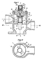
- Figure 2 shows the mixing valve of Figure 1, in longitudinal section on a larger scale.
- Figure 3 is a section of the mixing valve along line III-III of Figure 2.
- the invention relates to a thermostatic mixing valve 1 (the dimensions of which have been exaggerated in this figure) for the liquid cooling circuit of an internal combustion engine 2, this circuit being equipped a cooling radiator 3 and a circulation pump 4.
- the mixing valve 1 is mounted on a bypass 5 established between the pipe 6 of the circuit leading to the radiator 3 the hot coolant which leaves the engine 2 and the pipe 7, 8 bringing back to the engine 2 the cold coolant which leaves the radiator 3.
- the circulation pump 4 is mounted on the part 8 of the return pipe 7, 8 which is located downstream of the mixing valve 1.
- This ci is arranged so as to form, by mixing variable proportions of hot liquid (arriving via the bypass 5) and cold liquid (arriving via the pipe part 7), a lukewarm liquid which is then introduced into the motor 2 (via the pipe element 8) .
- the valve 1 comprises a thermostatic member 9 (FIG. 2), sensitive to the temperature of the warm liquid, which determines the respective proportions of hot liquid and cold liquid in the outgoing mixture or warm liquid.
- the valve 1 comprises a body 10 provided with an internally cylindrical part 11 into which the hot liquid and the cold liquid arrive, respectively through orifices 12 and 13 which are offset parallel to the axis XX of this cylindrical part 11.
- the body 10 can have either (as shown) a single orifice 12 for the arrival of the hot liquid, or several orifices 12 opening out in the same transverse plane, that is to say a plane perpendicular to axis XX.
- it can have either (as shown) a single orifice 13 for the arrival of the cold liquid, or several orifices 13 opening out in the same transverse plane.
- the body 10 of the valve 1 is further provided with an outlet orifice 15, for lukewarm liquid, at that of its axial ends which is the farthest from the inlet orifice 13 of the cold liquid, that is ie at its lower end according to FIG. 2, and it is closed at its opposite axial end by a removable transverse wall 16 serving as a support for the thermostatic member 9.
- the thermostatic member 9 consists of a wax capsule, the housing 17 of which is fixed to a perforated transverse partition 18 of the drawer 14, with a large transverse clearance inside the cylindrical part 11 of the body 10 and coaxially with this part. 11, so as to project from the side of the outlet orifice 15.
- the piston 19 of the wax capsule is supported on the transverse wall 16 of the body 10 towards which it is biased by a spring 20.
- the partition transverse 18, which may simply consist of radial arms 21 joining a central fixing hub 22 (for fixing the housing 17) to a cylindrical skirt 23, is made in one piece with the drawer 14 and is placed at that axial ends of the drawer 14 which is closest to the outlet orifice 15.
- An annular seal 34 mounted in a groove formed in the cylindrical part 11 between the orifices 12 and 13, cooperates with the skirt 23 d u drawer 14 to prevent leaks from occurring along the outer surface of the skirt 23.
- a mixing valve is thus obtained, the operation of which is as follows.
- the liquid known as "hot” normally arriving from the engine 2 via the pipe 5 to the orifice 12 of the valve 1 is in fact at ambient temperature, that is to say that its temperature is relatively low.
- the thermostatic member 9 is contracted and the slide 14 occupies, under the effect of the spring 20, its highest position, as shown in FIG. 2.
- the orifice 13 is therefore closed by the skirt 23, which prevents water from circulating in the radiator 3.
- the orifice 12 is opened wide and the coolant, circulated by the pump 4, rotates between the engine 2 and the valve 1 by passing through pipes 4 and 5 and bypassing the radiator 3.
- the transverse wall 16 of the body offers a fixed support for the thermostatic member 9.
- Such means are then advantageously constituted by a second wax capsule 24 mounted outside the body 10 and sensitive to the outside temperature or to the temperature prevailing under the engine hood 2.
- the housing this wax capsule 24 can be fixed directly to the transverse wall 16 of the body 10 so that its piston 25 passes through this wall 16 inside a guide 26, the seal with the outside being ensured by an annular seal 27 which cooperates with the outer surface of this guide 26.
- the outer wax capsule 24 could also be fixed at a distance from this wall 16. In this case, it would suffice to place, between the pistons 19 and 25, a transmission rod (not shown) passing through the transverse wall 16 as shown for the piston 25 in FIG. 2.
- the mixing valve 1 according to the invention in a single version, could adapt by itself to the temperature conditions which are defined, in the technical specifications of certain automobile manufacturers, as conditions “arctic”, “temperate” and “tropical”.
- the outer wax capsule 24 could be made sensitive to at least one operating parameter other than the temperature of the atmosphere in which it is placed (for example, another temperature, atmospheric pressure, etc.) by virtue of the presence of an electrical resistance 28 surrounding the casing of the wax capsule 24, or coated with a refractory material and embedded in the wax contained in this casing.
- the supply of this electrical resistance 28 by automatic means (microprocessors, in particular) or manual, depending on one or more operating parameters, then allows the operation of the mixing valve to be controlled by this or these parameters.
- the manufacture of the body 10 by molding, the mounting of the drawer 14 and of the elements associated with it and the adaptation of the mixing valve to the various variants mentioned above by way of example are facilitated by the constitution of the transverse wall. 16 by a separate piece and fixed to the body 10, for example by means of a crimping flange 29, with the interposition of a seal 30.
- the construction of the mixing valve according to the invention from a drawer, means that it is practically balanced in pressure, whatever the pressures at the orifices 12 and 13 of arrival of hot and cold liquid, contrary to the constructions of FR-A-2,434,723 and 1,472,712.
- the electrical resistance 28 can be a positive temperature coefficient thermistor (PTC).
- PTC positive temperature coefficient thermistor
- the parameters which influence the supply of the electrical resistance 28 can be, for example, at least one of the following: outside air temperature, temperature prevailing under the engine hood, atmospheric pressure, engine load, etc. ... and have an all or nothing action or a proportional action.
Landscapes
- Engineering & Computer Science (AREA)
- Physics & Mathematics (AREA)
- General Physics & Mathematics (AREA)
- Automation & Control Theory (AREA)
- Chemical & Material Sciences (AREA)
- Combustion & Propulsion (AREA)
- Mechanical Engineering (AREA)
- General Engineering & Computer Science (AREA)
- Temperature-Responsive Valves (AREA)
- Multiple-Way Valves (AREA)
Claims (7)
- Mischungsthermostatventil (1) für den Kühlflüssigkeitskreislauf bei Verbrennungsmotoren (2), die mit einem Kühler (3) und einer Umwälzpumpe (4) ausgestattet sind, hierbei ist das Ventil (1) zum Einbau in einer Zweigleitung (5) bestimmt, die zwischen der Leitung (6) des Kreislaufes, die die warme, aus dem Motor (2) herauskommende Kühlflüssigkeit zum Kühler (3) führt, und der Leitung (7,8) angeordnet ist, die die kalte vom Kühler (3) kommende Kühlflüssigkeit zum Motor (2) zurückführt, wobei jenes Mischventil (1) so eingerichtet ist, daß eine lauwarme Flüssigkeit durch Mischen in veränderlichen Proportionen von warmer Flüssigkeit und von kalter, vom Kühler (3) herauskommender Flüssigkeit gebildet wird, hierbei enthält jenes Ventil (1) eine Kapsel mit dehnbarem Wachs (9) üblicher Bauart, mit einem Gehäuse (17) und einem Kolben (19), die auf der Temperatur jener lauwarmen Flüssigkeit empfindlich ist und die Mischproportionen bestimmt, hierbei enthält das Ventil (1) einen Hohlkörper (10), der auf wenigstens einem Teil seiner inneren Länge zylindrisch ist, und einem Schieber (14), der eine gelochte, querliegende Trennwand (18) enthält, wobei der Schieber parallel zur Bewegungsachse (X-X), die mit der Achse des zylindrischen Teils übereinstimmt, bewegt werden kann durch die Wachskapsel (9) gegen den Druck einer Feder (20), und so im Körper (10) im zylin-drischen Teil eingelegt ist, daß die Einmündung der warmen Flüssigkeit (12) um so mehr geschlossen wird, und die Einmündung der kalten Flüssigkeit (13) gleichzeitig um so mehr geöffnet wird, desto höher die Temperatur der lauwarmen Flüssigkeit steigt und umgekehrt, hierbei sind die Einmündungen (12, 13) am Hohlkörper (10) versetzt angebracht, parallel zur flewegungsachse (X-X), die mit der Wirkungsachse der Wachskapsel (9) übereinstimmt, wobei der Hohlkörper (10) an einem seiner Enden an der Achse durch eine querliegende, feste, aber abnehmbare Querwand (16) begrenzt ist, und die Austrittsmündung (15) am gegengesetzten Ende der Achse (X-X) des zylindrischen Teiles des Hohlkörpers angebracht ist,
dadurch gekennzeichnet,
daß der Kolben (19) der Wachskapsel (9) sich auf die Querwand (16) des Ventilkörpers stützt, zu welcher er von der Feder (20) gedrückt wird, und daß das Gehäuse (17) der Wachskapsel (9) in der Achsrichtung des Schiebers (14) fest auf der Trennwand (18) eingebaut ist, so daß das Gehäuse (17) und der Schieber (14) sich gemeinsam durch die Wirkung der Ausdehnung der Wachskapsel (9) bewegen. - Mischventil nach Anspruch 1, dadurch gekennzeichnet, daß es Mittel enthält, um während des Betriebes durch Bezug auf den Körper (10) die Lage des Kolbens (19) der Wachskapsel (9) in Abhängigkeit äußerer Parameter einzustellen.
- Mischventil nach Anspruch 2, dadurch gekennzeichnet, daß die Einstellmittel der Lage des Kolbens (19) der Wachskapsel (9) eine außerhalb des Ventilkörpers (10) angebrachte zweite Wachskapsel (24) enthalten.
- Mischventil nach Anspruch 3, dadurch gekennzeichnet, daß das Gehäuse der zweiten Wachskapsel (24) mit der abnehmbaren Querwand (16) fest verbunden ist und, daß der Kolben (25) dieser zweiten Wachskapsel (24) die abnehmbare Querwand (16) mit dazwischen gelegenen Dichtungsmitteln (27) durchstößt, so daß er in der Achsrichtung den Kolben (19) der ersten Wachskapsel (9) berührt.
- Mischventil nach Anspruch 4, dadurch gekennzeichnet, daß die Dichtungsmittel (27) zwischen der abnehmbaren Querwand (16) und einer röhrenförmigen Führung (26) eingelegt sind, in welcher der Kolben (25) der zweiten Wachskapsel (24) verschiebbar eingebaut ist.
- Mischventil nach einem der Ansprüche 1 bis 5, dadurch gekennzeichnet, daß die querliegende Trennwand (18) aus strahlenförmig angeordneten Armen (21) besteht, die einen zentralen Befestigungsbereich (22) mit einem zylindrischen Wandbereich (23) verbindet.
- Mischventil nach einem der Ansprüche 1 bis 6, dadurch gekennzeichnet, daß die querliegende Trennwand (18 oder 21), an der das Gehäuse (17) der Wachskapsel (9) befestigt ist, einseitig mit dem Schieber (14) ausgebildet ist und an dem Achsende dieses Schiebers angebracht ist, das am nächsten zur Ausgangsmündung (15) der lauwarmen Flüssigkeit liegt.
Applications Claiming Priority (2)
| Application Number | Priority Date | Filing Date | Title |
|---|---|---|---|
| FR8515967A FR2589219B1 (fr) | 1985-10-28 | 1985-10-28 | Perfectionnements aux vannes mitigeuses thermostatiques pour circuits de refroidissement a liquide de moteurs a combustion interne |
| FR8515967 | 1985-10-28 |
Publications (2)
| Publication Number | Publication Date |
|---|---|
| EP0235472A1 EP0235472A1 (de) | 1987-09-09 |
| EP0235472B1 true EP0235472B1 (de) | 1991-04-10 |
Family
ID=9324256
Family Applications (1)
| Application Number | Title | Priority Date | Filing Date |
|---|---|---|---|
| EP86402395A Expired - Lifetime EP0235472B1 (de) | 1985-10-28 | 1986-10-27 | Mischungsthermostatventile für den Flüssigkeitskreislauf bei Verbrennungsmotoren |
Country Status (4)
| Country | Link |
|---|---|
| EP (1) | EP0235472B1 (de) |
| DE (1) | DE3678710D1 (de) |
| ES (1) | ES2021601B3 (de) |
| FR (1) | FR2589219B1 (de) |
Cited By (6)
| Publication number | Priority date | Publication date | Assignee | Title |
|---|---|---|---|---|
| EP0467130A1 (de) * | 1990-07-17 | 1992-01-22 | Firma J. Eberspächer | Thermostatventil mit übergeordnetem Verstellantrieb |
| FR2671378A1 (fr) * | 1991-01-08 | 1992-07-10 | Behr Thomson Dehnstoffregler | Soupape thermostatique pour regulation de la temperature du liquide de refroidissement d'un moteur a combustion interne, notamment d'un moteur de vehicule. |
| FR2684424A1 (fr) * | 1991-11-29 | 1993-06-04 | Behr Thomson Dehnstoffregler | Dispositif thermostatique insere a tiroir annulaire. |
| US5727729A (en) * | 1994-06-09 | 1998-03-17 | Rover Group Limited | Combined bypass and thermostat assembly |
| DE4448011B4 (de) * | 1993-07-19 | 2011-09-15 | Bayerische Motoren Werke Aktiengesellschaft | Kühlanlage für einen Verbrennungsmotor eines Kraftfahrzeuges mit einem Thermostatventil, das ein elektrisch beheizbares Dehnstoffelement enthält |
| DE102016106759A1 (de) * | 2016-04-13 | 2017-10-19 | Dr. Ing. H.C. F. Porsche Aktiengesellschaft | Kühlkreislauf und Verfahren zum Kühlen eines Kraftfahrzeugmotors |
Families Citing this family (11)
| Publication number | Priority date | Publication date | Assignee | Title |
|---|---|---|---|---|
| DE4233913C2 (de) * | 1992-10-08 | 2003-04-30 | Behr Thermot Tronik Gmbh | Elektrisch beheizbares Thermostatventil für einen Kühlmittelkreislauf eines Verbrennungsmotors |
| FR2703730B1 (fr) * | 1993-04-05 | 1995-06-23 | Vernet Sa | Perfectionnements aux circuits de refroidissement à liquide, pour moteurs à combustion interne. |
| DE29500897U1 (de) * | 1995-01-20 | 1996-05-30 | Behr-Thomson Dehnstoffregler Gmbh & Co, 70806 Kornwestheim | Thermostatventil |
| GB2325724B (en) * | 1997-07-04 | 1999-04-21 | Amot Controls Ltd | Device |
| DE10003135A1 (de) * | 2000-01-26 | 2001-08-02 | Wahler Gmbh & Co Kg Gustav | Ventil, insbesondere thermostatisches Ventil |
| FR2815106B1 (fr) * | 2000-10-05 | 2003-01-24 | Renault | Thermostat de circuit de refroidissement de moteur de vehicule automobile |
| DE102004035344B4 (de) † | 2004-07-21 | 2024-02-22 | Thermal Management Solutions DE Oberboihingen GmbH | Thermostatventil |
| FR2919704B1 (fr) * | 2007-08-01 | 2012-11-09 | Vernet | Vanne thermostatique a manchon,moteur thermique associe a un circuit de refroidissement comportant une telle vanne,et procede de fabrication d'un manchon pour une telle vanne |
| US8991719B2 (en) * | 2009-07-09 | 2015-03-31 | Dana Canada Corporation | Low pressure drop thermal by-pass valve |
| FR3086989B1 (fr) * | 2018-10-05 | 2020-10-23 | Novares France | Vanne thermostatique et vehicule comprenant cette vanne |
| FR3106640B1 (fr) | 2020-01-28 | 2022-02-18 | Vernet | Dispositif thermostatique pour réguler la circulation d’un fluide, ainsi que vanne thermostatique comprenant un tel dispositif |
Family Cites Families (4)
| Publication number | Priority date | Publication date | Assignee | Title |
|---|---|---|---|---|
| FR714947A (fr) * | 1931-04-08 | 1931-11-23 | Mélangeur automatique d'eau chaude et d'eau froide | |
| IT949211B (it) * | 1972-02-29 | 1973-06-11 | Knapp Alfons | Miscelatore termostatico per impianti idraulici |
| IT1000526B (it) * | 1973-12-18 | 1976-04-10 | Gilardini Ind Spa | Gruppo termostatico per circuiti di raffreddamento in particolare di motori a combustione interna |
| FR2434723A1 (fr) * | 1978-09-01 | 1980-03-28 | Vernet Expl Procedes | Perfectionnements aux installations de chauffage a air chaud pour habitacles de vehicules automobiles |
-
1985
- 1985-10-28 FR FR8515967A patent/FR2589219B1/fr not_active Expired
-
1986
- 1986-10-27 ES ES86402395T patent/ES2021601B3/es not_active Expired - Lifetime
- 1986-10-27 EP EP86402395A patent/EP0235472B1/de not_active Expired - Lifetime
- 1986-10-27 DE DE8686402395T patent/DE3678710D1/de not_active Revoked
Cited By (7)
| Publication number | Priority date | Publication date | Assignee | Title |
|---|---|---|---|---|
| EP0467130A1 (de) * | 1990-07-17 | 1992-01-22 | Firma J. Eberspächer | Thermostatventil mit übergeordnetem Verstellantrieb |
| FR2671378A1 (fr) * | 1991-01-08 | 1992-07-10 | Behr Thomson Dehnstoffregler | Soupape thermostatique pour regulation de la temperature du liquide de refroidissement d'un moteur a combustion interne, notamment d'un moteur de vehicule. |
| GB2252146A (en) * | 1991-01-08 | 1992-07-29 | Behr Thomson Dehnstoffregler | Thermostatic valve for an internal combustion engine cooling system |
| FR2684424A1 (fr) * | 1991-11-29 | 1993-06-04 | Behr Thomson Dehnstoffregler | Dispositif thermostatique insere a tiroir annulaire. |
| DE4448011B4 (de) * | 1993-07-19 | 2011-09-15 | Bayerische Motoren Werke Aktiengesellschaft | Kühlanlage für einen Verbrennungsmotor eines Kraftfahrzeuges mit einem Thermostatventil, das ein elektrisch beheizbares Dehnstoffelement enthält |
| US5727729A (en) * | 1994-06-09 | 1998-03-17 | Rover Group Limited | Combined bypass and thermostat assembly |
| DE102016106759A1 (de) * | 2016-04-13 | 2017-10-19 | Dr. Ing. H.C. F. Porsche Aktiengesellschaft | Kühlkreislauf und Verfahren zum Kühlen eines Kraftfahrzeugmotors |
Also Published As
| Publication number | Publication date |
|---|---|
| ES2021601B3 (es) | 1991-11-16 |
| DE3678710D1 (de) | 1991-05-16 |
| FR2589219B1 (fr) | 1988-05-13 |
| EP0235472A1 (de) | 1987-09-09 |
| FR2589219A1 (fr) | 1987-04-30 |
Similar Documents
| Publication | Publication Date | Title |
|---|---|---|
| EP0235472B1 (de) | Mischungsthermostatventile für den Flüssigkeitskreislauf bei Verbrennungsmotoren | |
| EP2524125B1 (de) | Schiebeventil und schaltung mit einem derartigen ventil | |
| WO2011110783A1 (fr) | Vanne thermostatique à manchon | |
| FR2696783A1 (fr) | Robinet thermostatique susceptible d'être chauffé électriquement pour circuit de refroidissement de moteur à combustion interne. | |
| FR2481791A1 (fr) | Echangeur de chaleur, en particulier pour un circuit de refroidissement d'un moteur de vehicule automobile | |
| FR2503252A1 (fr) | Installation de regulation thermostatique du liquide de refroidissement pour vehicules automobiles | |
| WO2015104325A1 (fr) | Vanne thermostatique | |
| FR2755756A1 (fr) | Composant modulaire pour circuit de fluide refrigerant, en particulier pour la climatisation de l'habitacle d'un vehicule automobile | |
| WO2021123021A1 (fr) | Dispositif de commande de l'écoulement d'un fluide | |
| WO2008093027A2 (fr) | Vanne thermostatique de regulation d'un fluide, circuit de liquide de refroidissement incorporant une telle vanne et procede de fabrication d'une telle vanne | |
| FR2827361A1 (fr) | Vanne de commande a fonctionnement securise pour circuit de circulation de fluide | |
| EP1486843B1 (de) | Thermostatventil für einen Flüssigkeitsströmungskreis und Verbrennungsmotor mit einem Flüssigkeitsströmungskreis, der diese Ventil beinhaltet | |
| WO2013083703A1 (fr) | Cartouche thermostatique de regulation de fluides chaud et froid a melanger | |
| FR2827357A1 (fr) | Vanne de commande pour un circuit de circulation de fluide, en particulier pour un circuit de refroidissement d'un moteur | |
| EP1041256A1 (de) | Thermostatische Vorrichtung mit zwei Thermostateinheiten für zwei Regelbereiche | |
| FR2560406A1 (fr) | Thermostat pour le circuit de refroidissement du moteur d'un vehicule automobile | |
| FR2601719A1 (fr) | Dispositif pour limiter la perte de charge d'un circuit de refroidissement d'un moteur a combustion interne et circuit de refroidissement equipe d'un tel dispositif | |
| EP0058933A1 (de) | Vorrichtung zur Temperatursteuerung und -regelung, insbesondere der Kühlflüssigkeit einer Brennkraftmaschine | |
| EP1614873A2 (de) | Ventil für einen Fluidiumkreislauf und Kreislauf einer Brennkraftmaschine mit solchem Ventil | |
| FR2839164A1 (fr) | Vanne de commande a fonctionnement securise et circuit de fluide equipe d'une telle vanne | |
| FR2597923A3 (fr) | Ensemble thermostatique pour le systeme de refroidissement d'un moteur thermique | |
| FR2850726A1 (fr) | Vanne de commande pour circuit de circulation de fluide, notamment de vehicule automobile | |
| FR2609111A1 (fr) | Dispositif de chauffage de carburant pour moteurs diesel | |
| FR2510707A1 (fr) | Vanne thermostatique pour commander l'ecoulement d'un liquide dans le circuit de refroidissement d'un moteur a combustion interne | |
| EP1556659B1 (de) | Wärmetauscher mit durchflussregelung, insbesondere für kraftfahrzeuge |
Legal Events
| Date | Code | Title | Description |
|---|---|---|---|
| PUAI | Public reference made under article 153(3) epc to a published international application that has entered the european phase |
Free format text: ORIGINAL CODE: 0009012 |
|
| AK | Designated contracting states |
Kind code of ref document: A1 Designated state(s): DE ES GB IT SE |
|
| 17P | Request for examination filed |
Effective date: 19871207 |
|
| 17Q | First examination report despatched |
Effective date: 19881208 |
|
| GRAA | (expected) grant |
Free format text: ORIGINAL CODE: 0009210 |
|
| AK | Designated contracting states |
Kind code of ref document: B1 Designated state(s): DE ES GB IT SE |
|
| ITF | It: translation for a ep patent filed | ||
| GBT | Gb: translation of ep patent filed (gb section 77(6)(a)/1977) | ||
| REF | Corresponds to: |
Ref document number: 3678710 Country of ref document: DE Date of ref document: 19910516 |
|
| PGFP | Annual fee paid to national office [announced via postgrant information from national office to epo] |
Ref country code: SE Payment date: 19910716 Year of fee payment: 6 |
|
| PGFP | Annual fee paid to national office [announced via postgrant information from national office to epo] |
Ref country code: GB Payment date: 19910802 Year of fee payment: 6 |
|
| PGFP | Annual fee paid to national office [announced via postgrant information from national office to epo] |
Ref country code: ES Payment date: 19910806 Year of fee payment: 6 |
|
| PGFP | Annual fee paid to national office [announced via postgrant information from national office to epo] |
Ref country code: DE Payment date: 19910822 Year of fee payment: 6 |
|
| PLBI | Opposition filed |
Free format text: ORIGINAL CODE: 0009260 |
|
| 26 | Opposition filed |
Opponent name: GUSTAV WAHLER GMBH U. CO. Effective date: 19910924 |
|
| PLBI | Opposition filed |
Free format text: ORIGINAL CODE: 0009260 |
|
| 26 | Opposition filed |
Opponent name: BEHR-THOMSON DEHNSTOFFREGLER GMBH & CO. Effective date: 19911115 Opponent name: GUSTAV WAHLER GMBH U. CO. Effective date: 19910924 |
|
| PG25 | Lapsed in a contracting state [announced via postgrant information from national office to epo] |
Ref country code: GB Effective date: 19921027 |
|
| PG25 | Lapsed in a contracting state [announced via postgrant information from national office to epo] |
Ref country code: SE Effective date: 19921028 |
|
| GBPC | Gb: european patent ceased through non-payment of renewal fee |
Effective date: 19921027 |
|
| RDAG | Patent revoked |
Free format text: ORIGINAL CODE: 0009271 |
|
| STAA | Information on the status of an ep patent application or granted ep patent |
Free format text: STATUS: PATENT REVOKED |
|
| 27W | Patent revoked |
Effective date: 19930514 |
|
| EUG | Se: european patent has lapsed |
Ref document number: 86402395.7 Effective date: 19930510 |