EP0235458A2 - Umblättereinrichtung für Dokumentenseiten - Google Patents
Umblättereinrichtung für Dokumentenseiten Download PDFInfo
- Publication number
- EP0235458A2 EP0235458A2 EP86309969A EP86309969A EP0235458A2 EP 0235458 A2 EP0235458 A2 EP 0235458A2 EP 86309969 A EP86309969 A EP 86309969A EP 86309969 A EP86309969 A EP 86309969A EP 0235458 A2 EP0235458 A2 EP 0235458A2
- Authority
- EP
- European Patent Office
- Prior art keywords
- page
- roller
- roller means
- passbook
- retrying
- Prior art date
- Legal status (The legal status is an assumption and is not a legal conclusion. Google has not performed a legal analysis and makes no representation as to the accuracy of the status listed.)
- Granted
Links
Images


Classifications
-
- G—PHYSICS
- G07—CHECKING-DEVICES
- G07F—COIN-FREED OR LIKE APPARATUS
- G07F19/00—Complete banking systems; Coded card-freed arrangements adapted for dispensing or receiving monies or the like and posting such transactions to existing accounts, e.g. automatic teller machines
- G07F19/20—Automatic teller machines [ATMs]
-
- B—PERFORMING OPERATIONS; TRANSPORTING
- B65—CONVEYING; PACKING; STORING; HANDLING THIN OR FILAMENTARY MATERIAL
- B65H—HANDLING THIN OR FILAMENTARY MATERIAL, e.g. SHEETS, WEBS, CABLES
- B65H15/00—Overturning articles
- B65H15/004—Overturning articles employing rollers
-
- G—PHYSICS
- G07—CHECKING-DEVICES
- G07F—COIN-FREED OR LIKE APPARATUS
- G07F19/00—Complete banking systems; Coded card-freed arrangements adapted for dispensing or receiving monies or the like and posting such transactions to existing accounts, e.g. automatic teller machines
- G07F19/20—Automatic teller machines [ATMs]
- G07F19/201—Accessories of ATMs
Definitions
- This invention relates to a document page turning apparatus.
- ATM automatic teller machines
- One of these functions is the automatic printing of information on passbooks and other types of multiple sheet or page documents.
- Mechanisms have been developed for automatically opening the cover and turning the pages of a passbook before printing is performed on the pages.
- a document page turning apparatus including feeding means adapted to feed a multiple page passbook along a feed path to a page turning position, page turning roller means positioned on one side of said feed path and adapted to engage a top page of the passbook, and pressing means operable to press the passbook against the roller means, the roller means being adapted to move the top page of the passbook to a partially turned position while the passbook is at said page turning position, following which the feeding means are operated to move the bound edge portion of the passbook along the feed path towards the roller means so as to complete the turning of the top page of the passbook.
- a difficulty that may be experienced with known page turning apparatuses such as that referred to above is that the apparatus may fail to complete the turning of a page in the event that the page is of reduced flexural rigidity or resilience due to previous usage or due to prior printing on the page.
- a document page turning apparatus including feeding means adapted to feed a document along a feed path to a page turning position, said document having a plurality of pages bound together at an edge portion of said document, page turning roller means positioned on one side of said feed path and adapted to engage an end page of said document, pressing means movable between operational and non-operational positions in which said pressing means presses, and does not press, respectively, said document against said roller means, said roller means being adapted to move an intermediate part of said end page away from said feed path by virtue of rotation of said roller means in a predetermined sense while said document is at said page turning position and said pressing means is in said operational position, and detecting means for detecting when said roller means has moved said part of said end page a predetermined distance away from said feed path, characterized by control means connected to said detecting means and arranged to control the operation of said feeding means and said roller means whereby, after said part of said document has been moved said predetermined distance away from said feed path, the following sequence of operations are brought about: rotation
- the page turning apparatus 20 shown therein includes a page turning roller 22 rotatably mounted on a support member 24, the roller 22 being arranged to be operated by conventional drive means in the manner of a stepping motor or the like and represented by page turning roller driving means 26.
- the roller 22 is mounted adjacent a plurality of guide plate members 28, 30 and 32 which form a feed path in the form of a chute or passageway 34.
- Mounted adjacent the guide chute 34 are a plurality of rubber, drive feed rollers 36, 38 operated by conventional motor-driven means represented by feed roller driving means 40, each of the drive rollers 36, 38 being arranged to coact with an associated pinch roller 42, 44 in a manner that is well known in the art to move a passbook (not shown in Fig. 1) along the guide chute 34.
- the pinch roller 44 is movable by pinch roller driving means 47 in a manner such that the pinch roller 44 is movable in a vertical direction towards or away from the drive roller 38.
- pressing pad or drive plate member 46 Located beneath the page turning roller 22 is a pressing pad or drive plate member 46 which is movable vertically by pressing pad driving means 48 which may be in the form of a solenoid or the like.
- a pair of sensors 50, 52 positioned under the passageway 34 have sensing devices 54, 56 which are responsive to and sense light beams 58, 60 from respective light sources 62, 64 positioned above the passageway 34.
- a sensor 66 positioned adjacent the pinch roller 42 includes a sensing device 68 responsive to and sensing a light beam 70 originating from a light source 72 adjacent the pinch roller 44.
- the sensing and interruption of the several light beams 58, 60 and 70 effects the sending of ON signals to a sequence controlling means 74 and to a retry controlling means 76 by way of a passbook location detecting means 78 and a page turning detecting means 80.
- the sequence controlling means 74 and the retry controlling means 76 include a microcomputer having a ROM and RAM and various associated interface devices. Such controlling means control the operation of the several driving or operating means in accordance with a program stored in the ROM and in response to a page turning instruction signal from external control means (not shown) and other signals from the passbook location detecting means 78 and the page turning detecting means 80.
- a passbook 82 having a bound edge portion 84 is driven by the feed rollers 36, 38 in a left-to-right direction to the page turning position shown in Fig. 2A.
- the passbook 82 is sensed by the pair of sensing devices or photodetectors 54, 56 (Fig. 1) which cooperate with the light sources 62, 64 in a manner that is well known in the art to sense the leading and trailing edges of the passbook 82.
- Signals generated by the sensing devices 54, 56 are transmitted to the passbook location detecting means 78, which detects whether the passbook 82 is in the page turning position.
- a reversible drive motor (not shown) operatively connected to the guide plate member 30 (Fig. 1) by any conventional means, such as a rack and pinion or like shutter mechanism, will slide the guide plate member 30 to the left as shown in Fig. 2A thereby removing the guide plate member from a blocking position with respect to the pressing pad 46.
- the sequence controlling means 74 in response to signals from sensors 50 and 52 over lines 86 and 88 (Fig.
- connection means 98 via connection means 98 and in response to a signal over line 100 from the sequence controlling means 74.
- a line 102 connects the sequence controlling means 74 with the feed roller driving means 40, and connection means 104 and 106 connect the feed roller driving means 40 to the feed rollers 36, 38.
- a connection means 108 connects the pinch roller driving means 47 with the pinch roller 44 for moving such roller upwardly after the guide plate member 30 is moved to the left (Fig. 2A).
- the passbook 82 is held in place by the rollers 36 and 42, and the pressing pad 46 presses the passbook 82 into contact with the roller 22.
- the pressing pad 46 is so constructed that, upon pressing upwardly against the passbook 82, it causes the passbook 82 to be curved or bowed in a configuration so that the free edge of the top page 96 at the left hand side 110 of the passbook 82 is drawn back from the free edges of the lower pages, permitting an arrangement which is effective for the page turning operation.
- Rotation of the page turning roller 22 in a counterclockwise direction results in the top page 96 being moved to a partially turned or raised curved position, as shown in Fig. 2B, in which position an intermediate part of the top page 96 (that is to say a part of the top page between its free edge and the bound edge portion 84) intercepts the light beam 70 outputted from the light source 72 and which is normally detected by the photodetector or sensing device 68 of sensor 66.
- the sensor 66 detects movement of part of the top page 96 a predetermined distance away from the passbook feed path.
- the interception of the light beam 70 by the top page 96 results in the photodetector member 68 being turned on and outputting a signal over line 112 (Fig.
- a signal is transmitted over line 114 from the detecting means 80 to the sequence controlling means 74.
- the controlling means 74 in response to receiving the signal from the detecting means 80 outputs a control signal over line 92 to the pressing pad driving means 48 which moves the pressing pad 46 in a downward direction (Fig. 2B), and also outputs a control signal to the page turning roller driving means 26 (Fig. 1) over line 100 which disables the driving means 26 and stops the rotation of the page turning roller 22.
- sequence controlling means 74 outputs a control signal over line 102 to the feed roller driving means 40 (Fig. 1) for rotating the feed rollers 36, 38 (Fig. 2C) in a counterclockwise direction.
- This counterclockwise rotation of the feed rollers 36, 38 results in the leftward movement of the passbook 82 by a distance "d", as viewed in Fig. 2C.
- the pinch roller 44 is then lowered to hold the passbook 82 except for the top page 96 and the page turning roller 22 is again rotated in a counterclockwise direction so as to move the free edge of the top page 96 past the axis of the roller 22 and to the position shown in Fig. 2D in which part of the page 96 is resting on the roller 22.
- the roller 22 may have difficulty in completing the turning of the top page 96 if the page 96 is of insufficient flexural rigidity.
- the top page 96 may be extremely flexible due to the nature of the paper or due to previous usage, in which case it may be very difficult for the roller 22 to turn the page by reason of slippage therewith due to there being insufficient frictional contact between the page 96 and the roller 22.
- a swelling or curvature as at 116 (Fig. 2D) may result from the pressing pad action and from the movement of the passbook 82 the distance "d" in the leftward direction.
- This swelling or curvature 116 can be smoothed out by rotation of the page turning roller 22 in a clockwise direction, as shown in Fig. 2E, where it is also noted that the pinch roller 44 has been raised to allow the passbook 82 to freely move in the leftward direction.
- the pinch roller 44 is again moved downward to make contact with and hold the passbook 82 against the drive roller 38 for moving the passbook leftward, as shown in Fig. 2F. It is seen that the page turning roller 22 is again rotating counterclockwise against the page 96 to completed the page turning operation. Then the passbook 82 is advanced in the leftward direction towards a printing mechanism (not shown) where printing is accomplished on the turned page 96.
- the top page 96 of the passbook 82 has sufficient resilience or flexural rigidity to respond to the operating elements of the page turning apparatus without an undue amount of waiting or without slippage of the roller 22.
- the page turning roller 22 may idle against the page without being effective in turning the page, even when the passbook 82 is moved the distance "d"; alternatively the page 96 may be so flimsy that it will fall downwardly when the pressing pad 46 is lowered.
- Figs. 3A-3C illustrate a first retrying routine involving re-executing some of the steps of the page turning operation.
- the first retrying routine is performed in the case where it is impossible to turn up the page 96 because the page turning roller 22 is idling, that is to say is slipping relative to the surface of the page, as shown in Fig. 3A.
- a cause of the condition may be due to reduced resilience of the passbook 82 against the bending or curving initiated by the pressing pad 46, with the result that the passbook is not in sufficient contact with the roller 22.
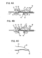
- Figs. 4A-4C illustrate a second retrying routine wherein the page turning operation is re-executed in the case wherein the page 96 cannot be kept or maintained in a partially turned up position.
- a situation occurs as the result of a condition, as shown in Fig. 4C, wherein the page 96 has a deformation 118 which prevents a resilient force between the roller 22 and the page 96 from acting on the page 96 in a generally horizontal direction.
- the second retrying routine is illustrated in Fig. 4B wherein the amount of rotation of the roller 22 is increased to bend the page 96 in a manner that provides for a tighter engagement or contact with the roller 22.
- the page bending is stepwise increased to positions a, b, and c (Fig. 4B) until the page can be turned up and maintained in its turned up state.
- the page 96 cannot be maintained in its partially turned up state, even at position c and after the passbook 82 is moved closer to the roller 22, as executed by the first retrying routine of Figs. 3A-3C, the first retrying routine is again performed until the deformed page 96 can be maintained in its partilly turned up state so as to complete the page turning operation.
- the sequence controlling means 74 and the retry controlling means 76 will be described.
- the sequence controlling means 74 is coupled with the retry controlling means 76 by means of path 115, and, as previously mentioned, the controlling means 74 and 76 include a microcomputer.
- the microcomputer controls the entire page turning operation.
- An embodiment of the controlling procedures effected by the controlling means 74 and 76 will now be described with reference to Figs. 1, 5A, 5B and 5C.
- a line 117 couples the page turning detecting means 80 and the retry controlling means 76
- a line 119 connects the retry controlling means 76 and the page turning roller driving means 26.
- Lines 121 and 123 connect the retry controlling means with the feed roller driving means 40 and with the pressing pad driving means 48, respectively.
- the sequence controlling means 74 clears (block 120) counters N1, N2 and N3 (not shown), which counters are used in a retry routine 1 or retry routine 2. Then, the feed roller driving means 40 (Fig. 1) is controlled by the sequence controlling means 74 over line 102 to rotate the feed rollers 36, 38 clockwise to feed the passbook 82 to the page turning position (block 122).
- the page turning detecting sensor 66 When the page turning detecting sensor 66 is turned on (as detected in block 164) during the gradual turning up of the page 96 by reason of the top page 96 intercepting the light beam 70 from the light source 72, the rotation of the page turning roller 22 is stopped (block 130) and the pressing pad 46 is moved downwards (block 132). Then, in block 134, the condition is checked to see whether the page turning detecting senser 66 is kept on or not, that is, whether the page 96 is maintained in the partially raised state or not.
- the turned on state of the sensor 66 causes the passbook 82 to be moved by several centimetres closer to the page turning roller 22 under the ON condition of the sensor, as indicated in block 136 (Fig. 5B).
- the page turning roller 22 is rotated counterclockwise to lift the page 96 so as to cause it to rest on the page turning roller 22 (blocks 138 and 140).
- the pinch roller 44 is raised and the page turning roller 22 is rotated clockwise (reversely rotated) to smooth out the swelling or curvature 116 of the passbook 82 (blocks 142 & 144).
- the passbook 82 is moved to the left, as viewed in Fig. 1, while rotating the page turning roller 22 counterclockwise (normal rotation) to complete the page turning operation (blocks 146, 148 and 150).
- N1 is set to "1".
- the flow is turned from block 160 to block 162 to move the passbook 82 closer to the page turning roller 22 by a distance of a few millimetres. Then, the flow is returned to block 126 over paths 163 and 169 to retry the turning over of the page 96 (blocks 126, 128, 164 and 152).
- the retry routine 1 is re-entered to further move the passbook 82 by a few millimeters closer to the page turning roller 22 in the same manner as that in the first retry (blocks 154, 156, 158, 160 and 162).
- N1 is increased to "2" and the process continues to block 162.
- the retry routine 1 is re-entered in block 152 from block 164.
- N1 is increased to "3" in block 158, so that the flow is shifted from block 160 to block 166 to move the passbook 82 a distance of a few centimetres closer to the page turning roller 22. Then, the flow is returned from block 168 to block 126 by way of path 169 to retry the partially turning up operation for the page. If it is still not possible to raise the page 96 to the required height, the retry routine 1 is re-entered in block 152. Then, N1 is increased to "4" in block 158 so that the flow extends again through block 166 and is directed through block 168 to an Error condition, as shown in block 191.
- the page 96 In normal operation, the page 96 should be maintained in its partially raised state even when the pressing pad 46 is moved downwards in block 132 (Fig. 5A). However, when the passbook 82 is deformed or curved, as shown at 118 in Fig. 4C, the resilient force of the passbook 82 against the page turning roller 22 is not horizontally applied to the roller 22, with the result that the page 96 tends to fall down, as shown in Fig. 4A. In this case, the page turning detecting sensor 66 is turned off, so that the control process enters the retry routine 2 by way of path 171 following the check in block 134 (Fig. 5A). In the retry routine 2 (Fig. 5C), the condition is checked in block 170 to ascertain whether or not N3 is "0".
- N3 is a counter indicating whether or not the retry routine 2 has previously been entered. N3 is set to "1" in block 172, and is held in this state until the page turning operation is completed. The routine is then advanced to block 174 in which N1 is cleared to "0". The reason for clearing N1 to "0" in block 174 is that there exists the possibility that the control process or procedure is entered in the retry routine 1 by the check at the step of block 152 before the entrance to the retry routine 2. Then, in block 176, the condition is checked to see whether or not the retry counter N2 for the retry routine 2 is set to "3". However, since N2 was cleared to zero at block 120 and kept in such state, the flow is advanced to blocks 178 and 180 (Fig.
- the flow re-enters the retry routine 2 in which case the retry operation is performed three times while changing the amount of rotation of the roller 22.
- the control operation is re-entered in the retry routine 1 to further move the passbook 82.
- the retrying routine 2 is performed three separate times for each time the passbook 82 is moved in the retry routine 1.
- the counter N1 is set to "4" in the block 158 (Fig. 5C) at the 4th entrance of the retry routine 1, so that it is judged ERROR in block 168 in the retry routine, and the process proceeds to block 191.
- the retrying operations are changed each time and are executed three times for each of the retrying routines 1 and 2, it is apparent that the present invention may be implemented such that each retrying operation is changed once in every two retrying operations, and that the number of retrying operations for each of the retrying routines 1 and 2 may be increased or decreased. Further, in place of or in addition to the above mentioned retrying routines, the rotating speed of the page turning roller 22 can be changed.
- the present invention is constructed such that the passbook can be moved closer to the page turning roller 22 after the page 96 has been partially turned up, and contact pressure between the page 96 and the page turning roller 22 is increased, so that it becomes possible to prevent the idle running of the page turning roller 22 and to lift the page 96 over such roller.
- the present invention is also constructed such that in case the page 96 can not be partially turned up due to the reduced flexural rigidity of the passbook 82, or the page 96 cannot be kept in its partially turned up state due to a deformed or curved passbook, a retrying routine is utilized.
- the passbook 82 is moved closer to the page turning roller 22, or the turning amount of the page 96 is increased, resulting in an increase in the resilient force of the passbook 82 and of the page 96 against bending, all in an arrangement wherein the partial turning up of the page and the maintaining of the page in such state are performed for successful completion of the page turning operation.
- a page turning apparatus and method for use with passbooks wherein the passbook is advanced a distance to ensure contact with a page turning roller and to re-execute the page turning operation in case the page is not partially turned up or is not maintained in the turned up condition.
- the method and apparatus provide for alternate operations of retrying routines in case of folded or curved passbooks or where the top page of the passbook has reduced resilience to bending.
Landscapes
- Business, Economics & Management (AREA)
- Accounting & Taxation (AREA)
- Finance (AREA)
- Physics & Mathematics (AREA)
- General Physics & Mathematics (AREA)
- Engineering & Computer Science (AREA)
- Mechanical Engineering (AREA)
- Financial Or Insurance-Related Operations Such As Payment And Settlement (AREA)
- Handling Of Cut Paper (AREA)
- Sheets, Magazines, And Separation Thereof (AREA)
- Registering Or Overturning Sheets (AREA)
- Folding Of Thin Sheet-Like Materials, Special Discharging Devices, And Others (AREA)
Applications Claiming Priority (2)
| Application Number | Priority Date | Filing Date | Title |
|---|---|---|---|
| JP60285901A JPS62148297A (ja) | 1985-12-20 | 1985-12-20 | 冊子類の頁めくり装置 |
| JP285901/85 | 1985-12-20 |
Publications (3)
| Publication Number | Publication Date |
|---|---|
| EP0235458A2 true EP0235458A2 (de) | 1987-09-09 |
| EP0235458A3 EP0235458A3 (en) | 1989-06-28 |
| EP0235458B1 EP0235458B1 (de) | 1992-02-19 |
Family
ID=17697486
Family Applications (1)
| Application Number | Title | Priority Date | Filing Date |
|---|---|---|---|
| EP86309969A Expired EP0235458B1 (de) | 1985-12-20 | 1986-12-19 | Umblättereinrichtung für Dokumentenseiten |
Country Status (5)
| Country | Link |
|---|---|
| US (1) | US4700497A (de) |
| EP (1) | EP0235458B1 (de) |
| JP (1) | JPS62148297A (de) |
| DE (2) | DE3683939D1 (de) |
| ES (1) | ES2029452T3 (de) |
Cited By (5)
| Publication number | Priority date | Publication date | Assignee | Title |
|---|---|---|---|---|
| EP0684587A1 (de) * | 1994-05-27 | 1995-11-29 | International Business Machines Corporation | Verfahren und Vorrichtung zum Umblättern der Seiten eines Buches |
| EP0684588A1 (de) * | 1994-05-27 | 1995-11-29 | International Business Machines Corporation | Vorrichtung und Verfahren zum Umblättern der Seiten eines Buches |
| EP0889451A1 (de) * | 1997-07-02 | 1999-01-07 | Fujitsu Limited | Vorrichtung zum Umblättern |
| ES2213409A1 (es) * | 1999-04-16 | 2004-08-16 | Fujitsu Limited | Dispositivo de transaccion automatica y metodo para controlar dicho dispositivo. |
| KR100818386B1 (ko) * | 2006-06-29 | 2008-04-02 | 후지츠 프론테크 가부시키가이샤 | 통장 페이지 넘김 동작 제어장치 |
Families Citing this family (44)
| Publication number | Priority date | Publication date | Assignee | Title |
|---|---|---|---|---|
| JPH0780369B2 (ja) * | 1986-03-19 | 1995-08-30 | 株式会社日立製作所 | ペ−ジ替え装置 |
| JPS6371396A (ja) * | 1986-09-16 | 1988-03-31 | 株式会社日立製作所 | 通帳頁替制御方法 |
| JPH02301489A (ja) * | 1989-04-28 | 1990-12-13 | Ncr Corp | 冊子類の頁捲装置 |
| JPH07119155B2 (ja) * | 1989-07-10 | 1995-12-20 | 沖電気工業株式会社 | 冊子の自動頁めくり方法 |
| US5267799A (en) * | 1989-11-24 | 1993-12-07 | Kabushiki Kaisha Toshiba | Apparatus and method of printing data in a book, a notebook, or the like |
| DE69026690T2 (de) * | 1989-11-24 | 1996-11-14 | Toshiba Kawasaki Kk | Vorrichtung zum Datenaufdrücken in einem Buch, einem Notizbuch oder ähnlichem |
| US5183347A (en) * | 1989-12-15 | 1993-02-02 | Kabushiki Kaisha Toshiba | Apparatus for printing images on booklets |
| KR940009386B1 (ko) * | 1990-05-30 | 1994-10-07 | 가부시끼가이샤 히다찌세이사꾸쇼 | 책자류 프린터 및 페이지 교체장치 |
| JP2619157B2 (ja) * | 1991-07-22 | 1997-06-11 | 沖電気工業株式会社 | 自動改頁装置 |
| JPH09156255A (ja) * | 1995-12-07 | 1997-06-17 | Hitachi Ltd | ページ替え装置 |
| JP3964046B2 (ja) * | 1998-04-27 | 2007-08-22 | 富士通株式会社 | ページ捲り装置およびページ捲り方法 |
| ES2319016A1 (es) * | 2003-12-26 | 2009-05-01 | Fujitsu Frontech Limited | Metodo y aparato de control para una operacion de paso de pagina de libreta. |
| WO2005065961A1 (ja) * | 2003-12-26 | 2005-07-21 | Fujitsu Frontech Limited | 通帳ページ捲り動作の制御方法及び装置 |
| US7775966B2 (en) | 2005-02-24 | 2010-08-17 | Ethicon Endo-Surgery, Inc. | Non-invasive pressure measurement in a fluid adjustable restrictive device |
| US7658196B2 (en) | 2005-02-24 | 2010-02-09 | Ethicon Endo-Surgery, Inc. | System and method for determining implanted device orientation |
| US8016744B2 (en) | 2005-02-24 | 2011-09-13 | Ethicon Endo-Surgery, Inc. | External pressure-based gastric band adjustment system and method |
| US7699770B2 (en) | 2005-02-24 | 2010-04-20 | Ethicon Endo-Surgery, Inc. | Device for non-invasive measurement of fluid pressure in an adjustable restriction device |
| US7775215B2 (en) | 2005-02-24 | 2010-08-17 | Ethicon Endo-Surgery, Inc. | System and method for determining implanted device positioning and obtaining pressure data |
| US7927270B2 (en) | 2005-02-24 | 2011-04-19 | Ethicon Endo-Surgery, Inc. | External mechanical pressure sensor for gastric band pressure measurements |
| US8066629B2 (en) | 2005-02-24 | 2011-11-29 | Ethicon Endo-Surgery, Inc. | Apparatus for adjustment and sensing of gastric band pressure |
| US8870742B2 (en) | 2006-04-06 | 2014-10-28 | Ethicon Endo-Surgery, Inc. | GUI for an implantable restriction device and a data logger |
| US8152710B2 (en) | 2006-04-06 | 2012-04-10 | Ethicon Endo-Surgery, Inc. | Physiological parameter analysis for an implantable restriction device and a data logger |
| JP4416785B2 (ja) | 2006-12-27 | 2010-02-17 | インターナショナル・ビジネス・マシーンズ・コーポレーション | 通帳の頁めくりをする装置、方法、および制御プログラム |
| US7866661B2 (en) * | 2007-08-29 | 2011-01-11 | Pitney Bowes Inc. | Sheet/page buffer for sheet handling apparatus |
| US8187163B2 (en) | 2007-12-10 | 2012-05-29 | Ethicon Endo-Surgery, Inc. | Methods for implanting a gastric restriction device |
| US8100870B2 (en) | 2007-12-14 | 2012-01-24 | Ethicon Endo-Surgery, Inc. | Adjustable height gastric restriction devices and methods |
| US8377079B2 (en) | 2007-12-27 | 2013-02-19 | Ethicon Endo-Surgery, Inc. | Constant force mechanisms for regulating restriction devices |
| US8142452B2 (en) | 2007-12-27 | 2012-03-27 | Ethicon Endo-Surgery, Inc. | Controlling pressure in adjustable restriction devices |
| US8337389B2 (en) | 2008-01-28 | 2012-12-25 | Ethicon Endo-Surgery, Inc. | Methods and devices for diagnosing performance of a gastric restriction system |
| US8192350B2 (en) | 2008-01-28 | 2012-06-05 | Ethicon Endo-Surgery, Inc. | Methods and devices for measuring impedance in a gastric restriction system |
| US8591395B2 (en) | 2008-01-28 | 2013-11-26 | Ethicon Endo-Surgery, Inc. | Gastric restriction device data handling devices and methods |
| US7844342B2 (en) | 2008-02-07 | 2010-11-30 | Ethicon Endo-Surgery, Inc. | Powering implantable restriction systems using light |
| US8221439B2 (en) | 2008-02-07 | 2012-07-17 | Ethicon Endo-Surgery, Inc. | Powering implantable restriction systems using kinetic motion |
| US8114345B2 (en) | 2008-02-08 | 2012-02-14 | Ethicon Endo-Surgery, Inc. | System and method of sterilizing an implantable medical device |
| US8591532B2 (en) | 2008-02-12 | 2013-11-26 | Ethicon Endo-Sugery, Inc. | Automatically adjusting band system |
| US8057492B2 (en) | 2008-02-12 | 2011-11-15 | Ethicon Endo-Surgery, Inc. | Automatically adjusting band system with MEMS pump |
| US8034065B2 (en) | 2008-02-26 | 2011-10-11 | Ethicon Endo-Surgery, Inc. | Controlling pressure in adjustable restriction devices |
| US8187162B2 (en) | 2008-03-06 | 2012-05-29 | Ethicon Endo-Surgery, Inc. | Reorientation port |
| US8233995B2 (en) | 2008-03-06 | 2012-07-31 | Ethicon Endo-Surgery, Inc. | System and method of aligning an implantable antenna |
| GB0812966D0 (en) * | 2008-07-16 | 2008-08-20 | Cnh Belgium Nv | Cleaning of an air filter screen of an agricultural vehicle |
| JP5910575B2 (ja) * | 2013-06-25 | 2016-04-27 | カシオ計算機株式会社 | 書画カメラシステム及び画像読み取り方法 |
| JP6260606B2 (ja) * | 2015-11-27 | 2018-01-17 | カシオ計算機株式会社 | 書画カメラシステム及び画像読み取り方法 |
| CN113744470B (zh) * | 2021-08-30 | 2024-10-18 | 北京兆维电子(集团)有限责任公司 | 一种翻页装置及存折处理设备 |
| CN113844193B (zh) * | 2021-10-08 | 2022-05-20 | 常州汉威信科技股份有限公司 | 文书翻页机构及文书正反翻页机构 |
Citations (3)
| Publication number | Priority date | Publication date | Assignee | Title |
|---|---|---|---|---|
| US4280036A (en) * | 1978-10-24 | 1981-07-21 | Tokyo Shibaura Denki Kabushiki Kaisha | Banking apparatus using passbooks |
| GB2103585A (en) * | 1981-07-31 | 1983-02-23 | Tokyo Shibaura Electric Co | A page turning apparatus |
| US4545141A (en) * | 1983-09-30 | 1985-10-08 | Ncr Corporation | Automatic document page turning apparatus |
Family Cites Families (2)
| Publication number | Priority date | Publication date | Assignee | Title |
|---|---|---|---|---|
| JPS5820497A (ja) * | 1981-07-31 | 1983-02-05 | 株式会社東芝 | 印字装置 |
| US4663873A (en) * | 1985-12-20 | 1987-05-12 | Xerox Corporation | Page flipper for book copying |
-
1985
- 1985-12-20 JP JP60285901A patent/JPS62148297A/ja active Granted
-
1986
- 1986-09-08 US US06/905,096 patent/US4700497A/en not_active Expired - Lifetime
- 1986-12-19 EP EP86309969A patent/EP0235458B1/de not_active Expired
- 1986-12-19 DE DE8686309969T patent/DE3683939D1/de not_active Expired - Lifetime
- 1986-12-19 DE DE198686309969T patent/DE235458T1/de active Pending
- 1986-12-19 ES ES198686309969T patent/ES2029452T3/es not_active Expired - Lifetime
Patent Citations (3)
| Publication number | Priority date | Publication date | Assignee | Title |
|---|---|---|---|---|
| US4280036A (en) * | 1978-10-24 | 1981-07-21 | Tokyo Shibaura Denki Kabushiki Kaisha | Banking apparatus using passbooks |
| GB2103585A (en) * | 1981-07-31 | 1983-02-23 | Tokyo Shibaura Electric Co | A page turning apparatus |
| US4545141A (en) * | 1983-09-30 | 1985-10-08 | Ncr Corporation | Automatic document page turning apparatus |
Cited By (7)
| Publication number | Priority date | Publication date | Assignee | Title |
|---|---|---|---|---|
| EP0684587A1 (de) * | 1994-05-27 | 1995-11-29 | International Business Machines Corporation | Verfahren und Vorrichtung zum Umblättern der Seiten eines Buches |
| EP0684588A1 (de) * | 1994-05-27 | 1995-11-29 | International Business Machines Corporation | Vorrichtung und Verfahren zum Umblättern der Seiten eines Buches |
| US5794365A (en) * | 1994-05-27 | 1998-08-18 | International Business Machines Corporation | Method and apparatus for turning a page in a book |
| US6103963A (en) * | 1997-02-07 | 2000-08-15 | Fujitsu Limited | Page turning apparatus |
| EP0889451A1 (de) * | 1997-07-02 | 1999-01-07 | Fujitsu Limited | Vorrichtung zum Umblättern |
| ES2213409A1 (es) * | 1999-04-16 | 2004-08-16 | Fujitsu Limited | Dispositivo de transaccion automatica y metodo para controlar dicho dispositivo. |
| KR100818386B1 (ko) * | 2006-06-29 | 2008-04-02 | 후지츠 프론테크 가부시키가이샤 | 통장 페이지 넘김 동작 제어장치 |
Also Published As
| Publication number | Publication date |
|---|---|
| EP0235458B1 (de) | 1992-02-19 |
| EP0235458A3 (en) | 1989-06-28 |
| JPH0566276B2 (de) | 1993-09-21 |
| JPS62148297A (ja) | 1987-07-02 |
| ES2029452T3 (es) | 1992-08-16 |
| DE3683939D1 (de) | 1992-03-26 |
| DE235458T1 (de) | 1988-02-25 |
| US4700497A (en) | 1987-10-20 |
Similar Documents
| Publication | Publication Date | Title |
|---|---|---|
| EP0235458B1 (de) | Umblättereinrichtung für Dokumentenseiten | |
| US6428226B1 (en) | Paper discharge apparatus | |
| EP0616963B1 (de) | Apparat zum Handhaben von Bögen | |
| US4459052A (en) | Apparatus for dispensing valuable papers and other documents | |
| EP0352813B1 (de) | Bogenzuführvorrichtung für eine Reproduzier- und Behandlungsmaschine | |
| EP0448257B2 (de) | Blattzuführ- und Ausrichtsystem für einen Drucker | |
| KR940009386B1 (ko) | 책자류 프린터 및 페이지 교체장치 | |
| AU609276B2 (en) | Sheet picking mechanism | |
| JPH0532356A (ja) | 画像形成装置の給紙装置 | |
| US5330316A (en) | Sheet handling apparatus and method | |
| EP0312009A2 (de) | Kartenleser | |
| US6029971A (en) | Sheet feeding apparatus | |
| US5195738A (en) | Single sheet picking and transport mechanism | |
| US4877232A (en) | Paper discharge apparatus | |
| US6135440A (en) | Sheet feeding apparatus | |
| EP0996936A1 (de) | Zusätzlicher apparat zum behandeln von sparbücher und verfahren dazu | |
| EP0542226B1 (de) | Vorrichtung zum Vereinzeln und Zuführen von Papierblättern und Steuerungsverfahren dafür, und dieses Verfahren verwendender Kassenautomat | |
| JP2641275B2 (ja) | 紙葉類堆積・繰り出し装置 | |
| EP0405466B1 (de) | Einzelblattaufnahme- und -transporteinrichtung | |
| KR101713619B1 (ko) | 통장정리기의 자동 페이지 넘김장치 | |
| KR100539440B1 (ko) | 양방향 이월 및 이월매수인식 가능한 통장류 페이지이월장치 | |
| JPH11106058A (ja) | 印刷方法及び印刷装置 | |
| JPS61231689A (ja) | 現金自動取引装置 | |
| JPH03211147A (ja) | 紙葉類搬送装置のスキュー検知機構 | |
| JPH0732766A (ja) | 自動改頁機構 |
Legal Events
| Date | Code | Title | Description |
|---|---|---|---|
| PUAI | Public reference made under article 153(3) epc to a published international application that has entered the european phase |
Free format text: ORIGINAL CODE: 0009012 |
|
| AK | Designated contracting states |
Kind code of ref document: A2 Designated state(s): DE ES FR GB |
|
| EL | Fr: translation of claims filed | ||
| DET | De: translation of patent claims | ||
| PUAL | Search report despatched |
Free format text: ORIGINAL CODE: 0009013 |
|
| AK | Designated contracting states |
Kind code of ref document: A3 Designated state(s): DE ES FR GB |
|
| 17P | Request for examination filed |
Effective date: 19891223 |
|
| 17Q | First examination report despatched |
Effective date: 19910528 |
|
| GRAA | (expected) grant |
Free format text: ORIGINAL CODE: 0009210 |
|
| AK | Designated contracting states |
Kind code of ref document: B1 Designated state(s): DE ES FR GB |
|
| REF | Corresponds to: |
Ref document number: 3683939 Country of ref document: DE Date of ref document: 19920326 |
|
| RAP2 | Party data changed (patent owner data changed or rights of a patent transferred) |
Owner name: NCR INTERNATIONAL INC. |
|
| ET | Fr: translation filed | ||
| REG | Reference to a national code |
Ref country code: ES Ref legal event code: FG2A Ref document number: 2029452 Country of ref document: ES Kind code of ref document: T3 |
|
| PLBE | No opposition filed within time limit |
Free format text: ORIGINAL CODE: 0009261 |
|
| STAA | Information on the status of an ep patent application or granted ep patent |
Free format text: STATUS: NO OPPOSITION FILED WITHIN TIME LIMIT |
|
| 26N | No opposition filed | ||
| REG | Reference to a national code |
Ref country code: GB Ref legal event code: IF02 |
|
| PGFP | Annual fee paid to national office [announced via postgrant information from national office to epo] |
Ref country code: ES Payment date: 20021001 Year of fee payment: 17 |
|
| PGFP | Annual fee paid to national office [announced via postgrant information from national office to epo] |
Ref country code: GB Payment date: 20030929 Year of fee payment: 18 |
|
| REG | Reference to a national code |
Ref country code: GB Ref legal event code: 746 Effective date: 20030924 |
|
| PGFP | Annual fee paid to national office [announced via postgrant information from national office to epo] |
Ref country code: FR Payment date: 20031031 Year of fee payment: 18 |
|
| PGFP | Annual fee paid to national office [announced via postgrant information from national office to epo] |
Ref country code: DE Payment date: 20031201 Year of fee payment: 18 |
|
| PG25 | Lapsed in a contracting state [announced via postgrant information from national office to epo] |
Ref country code: ES Free format text: LAPSE BECAUSE OF NON-PAYMENT OF DUE FEES Effective date: 20031220 |
|
| REG | Reference to a national code |
Ref country code: FR Ref legal event code: D6 |
|
| PG25 | Lapsed in a contracting state [announced via postgrant information from national office to epo] |
Ref country code: GB Free format text: LAPSE BECAUSE OF NON-PAYMENT OF DUE FEES Effective date: 20041219 |
|
| REG | Reference to a national code |
Ref country code: ES Ref legal event code: FD2A Effective date: 20031220 |
|
| PG25 | Lapsed in a contracting state [announced via postgrant information from national office to epo] |
Ref country code: DE Free format text: LAPSE BECAUSE OF NON-PAYMENT OF DUE FEES Effective date: 20050701 |
|
| GBPC | Gb: european patent ceased through non-payment of renewal fee |
Effective date: 20041219 |
|
| PG25 | Lapsed in a contracting state [announced via postgrant information from national office to epo] |
Ref country code: FR Free format text: LAPSE BECAUSE OF NON-PAYMENT OF DUE FEES Effective date: 20050831 |
|
| REG | Reference to a national code |
Ref country code: FR Ref legal event code: ST |