EP0231889B1 - Motor mit innenliegendem Kondensator - Google Patents
Motor mit innenliegendem Kondensator Download PDFInfo
- Publication number
- EP0231889B1 EP0231889B1 EP87101247A EP87101247A EP0231889B1 EP 0231889 B1 EP0231889 B1 EP 0231889B1 EP 87101247 A EP87101247 A EP 87101247A EP 87101247 A EP87101247 A EP 87101247A EP 0231889 B1 EP0231889 B1 EP 0231889B1
- Authority
- EP
- European Patent Office
- Prior art keywords
- capacitor
- motor according
- stator
- coils
- capacitor motor
- Prior art date
- Legal status (The legal status is an assumption and is not a legal conclusion. Google has not performed a legal analysis and makes no representation as to the accuracy of the status listed.)
- Expired
Links
- 239000003990 capacitor Substances 0.000 title claims description 65
- 238000004804 winding Methods 0.000 claims description 30
- 239000012212 insulator Substances 0.000 claims description 17
- 239000004020 conductor Substances 0.000 claims description 13
- 230000002093 peripheral effect Effects 0.000 claims description 3
- 230000006698 induction Effects 0.000 description 9
- 230000004907 flux Effects 0.000 description 3
- 238000000034 method Methods 0.000 description 3
- XLYOFNOQVPJJNP-UHFFFAOYSA-N water Substances O XLYOFNOQVPJJNP-UHFFFAOYSA-N 0.000 description 3
- 239000000314 lubricant Substances 0.000 description 2
- 239000002184 metal Substances 0.000 description 2
- 241000555745 Sciuridae Species 0.000 description 1
- 238000004140 cleaning Methods 0.000 description 1
- 238000009413 insulation Methods 0.000 description 1
- 239000002648 laminated material Substances 0.000 description 1
- 238000003475 lamination Methods 0.000 description 1
- 238000005461 lubrication Methods 0.000 description 1
- 238000005057 refrigeration Methods 0.000 description 1
- 238000007789 sealing Methods 0.000 description 1
- 238000005476 soldering Methods 0.000 description 1
- 230000001360 synchronised effect Effects 0.000 description 1
Images
Classifications
-
- H—ELECTRICITY
- H02—GENERATION; CONVERSION OR DISTRIBUTION OF ELECTRIC POWER
- H02K—DYNAMO-ELECTRIC MACHINES
- H02K17/00—Asynchronous induction motors; Asynchronous induction generators
- H02K17/02—Asynchronous induction motors
- H02K17/30—Structural association of asynchronous induction motors with auxiliary electric devices influencing the characteristics of the motor or controlling the motor, e.g. with impedances or switches
-
- H—ELECTRICITY
- H02—GENERATION; CONVERSION OR DISTRIBUTION OF ELECTRIC POWER
- H02K—DYNAMO-ELECTRIC MACHINES
- H02K17/00—Asynchronous induction motors; Asynchronous induction generators
- H02K17/02—Asynchronous induction motors
- H02K17/04—Asynchronous induction motors for single phase current
- H02K17/08—Motors with auxiliary phase obtained by externally fed auxiliary windings, e.g. capacitor motors
Definitions
- THIS INVENTION relates to capacitors within a motor and, more particularly, to capacitors which have, in the past, been connected to an electric motor.
- Such motors may be single-phase induction motors with a capacitor connected to a winding to establish a split phase primarily to establish starting torque.
- a typical motor of this type has a metal, cylindrical can housing with the capacitor mounted on the outside of the electric motor frame.
- the manufacturer has found room to place the capacitor inside the motor, for example, within the end bell.
- this entails using an elongated end bell and an elongated motor to provide space for such a capacitor.
- a half-pitch capacitor induction motor operable on single-phase and having balanced main and auxiliary windings has been disclosed in U.S. Patent 4,371,802.
- Such a motor has coils surrounding individual pole pieces rather than the usual distributed winding most often found in single-phase induction motors.
- the capacitor is mounted externally to the motor.
- the problem to be solved is haw to construct a capacitor-type motor which may be mounted in a motor frame without an external capacitor housing, yet retaining the same size of motor frame so as to be completely interchangeable with a resistance split-phase motor.
- the present invention provides a capacitor motor comprising, in combination: a magnetically permeable stator; having a plurality of salient teeth establishing a plurality of pole faces thereon; a rotor journalled relative to the stator and magnetically cooperating with the pole faces across an air gap; a stator winding having a plurality of coils on the salient teeth, the coils and teeth having a width in the peripheral direction less than the width of the respective pole face to define a plurality of spaces between at least some of the adjacent coils characterized by at least one elongated capacitor disposed in one of the spaces; and means for connecting said capacitor to said stator winding.
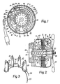
- FIGS 1 and 2 show an electric motor 11 which has a frame 12 and a magnetically permeable stator 13.
- This motor 11 may be any one of a number of types, for example, a synchronous motor of the hysteresis or reluctance type, or may be of a type having a permanent magnet for synchronization and utilising induction motor starting. Most of such motors would be single-phase and utilise a capacitor as connected to a part of the stator winding. Such motors may be single-phase induct ion motors which are capacitor-start utilising a start switch to open the capacitor winding at near running speed, or they may be the more popular permanent split capacitor motor without a starting switch. This latter type of motor is illustrated in Figures 1, 2 and 3, as an example of the preferred embodiment.
- the motor shown in the Figures is a half-pitch capacitor induction motor, similar to that shown in the prior Patent 4,371,802.
- the stator has an even plurality of salient teeth 14 establishing a plurality of pole faces 15 on the stator. These salient teeth extend substantially radially inwardly toward a rotor 16, which is also magnetically permeable.
- both the rotor and stator are made from laminated material to reduce eddy currents produced by the alternating current.
- the rotor 16 has skewed conductor bars 17 extending longitudinally through apertures in the rotor and joined by unitary end rings 18 to form a squirrel cage rotor cooperating across the air gap 19 with the pole faces 15.
- the rotor 16 is mounted on a hub 21 which is hermetically mounted to a central shaft 22 and this shaft is journalled in an apertured central extension 23 of the frame 12.
- the shaft 22 may contain a helical groove 24 to move oil or an other lubricant from a lubricant reservoir 25 secured to one end of the frame 12. This provides lubrication between the shaft 22 and the central extension 23.
- the shaft 22, hub 21, and laminations of the rotor 16 are all integral and rotate together.
- the rotor is adapted to drive a load such as the fan blade 26 which is secured to the shaft by a nut 27.
- the stator 13 includes a stator winding 30 which comprises a main winding 31 and on auxiliary winding 32.
- each winding has an equal number of poles and includes one coil per pole.
- Figure 1 illustrates one embodiment of the invention in the form of a four-pole motor. Accordingly, the main winding has coils 33, 35, 37, and 39 connected in series by a conductor 41, and the auxiliary winding 32 has coils 34, 36, 38, and 40 connected in series by a conductor 45.
- the series main winding coils are connected across the input AC voltage source, and the series auxiliary winding coils are connected in series with capacitive means 42 and then across the AC voltage source.
- the capacitive means 42 includes one or more capacitors 43 which, in practice, may be three or four individual capacitors 43 mounted on an insulator 44.
- the insulator is a rigid, arcuate insulator with a radius equal to the radial distance between the shaft axis 28 and the midpoint of the coils 33-40.
- each coil is made from a conductor which is as short as possible to establish magnetic flux in the respective tooth.
- one individual coil per tooth establishes spaces 46 between adjacent coils in a peripheral direction, and it is in these spaces 46 in which the one or more capacitors 43 are installed.
- First and second conductors 47 and 48 are provided on the insulator 44 and these may be provided by printed circuit board techniques or thick film techniques customary in the industry.
- the insulator board 44 is provided with small apertures through the board which intersect the conductors 47 and 48.
- Each individual capacitor 43 is provided with an insulating sheath 49 for further insulation between the capacitors and the coils, and each capacitor has first and second leads 51 and 52 which pass through the apertures in the insulator 44 and are electrically connected to the conductors 47 and 48 respectively. This may be achieved by, for example, wave soldering. as at 53, and provides mechanical support for the capacitor from the insulator as well as electrical connection to the conductors 47 and 48.
- Lead wires 54 and 55 extend from the conductors 47 and 48, respectively, to binding posts 56 and 57.
- a third binding post 58 is also provided on the stator 13, and these three binding posts may be utilised as terminations for the main and auxiliary windings for connection to two leads 59 and 60, which permit connection to an external AC source.
- FIG. 3 The subcombination of the insulator 44 and capacitors 43 is shown in Figure 3 as removed from the motor, and Figures 1 and 2 show the capacitors installed inside the motor with the insulator board 44 positioned closely adjacent one end of a plurality of coils 33-40 and the capacitors 43 installed in four of the spaces 46.
- stator teeth are symmetrically placed around the periphery of the stator, which ensures that the spaces 46 are also symmetrically spaced, although they may be asymmetrical in order to provide additional space at certain preferred locations at which the capacitors could be located.
- the pole faces are all symmetrical for a balanced half-pitch capacitor induction motor which is energized by single-phase, but actually creates a two-phase motor, with the auxiliary winding 32 establishing a flux electrically displaced substantially 90 degrees from the flux of the main winding 31. This provides a highly efficient motor in the subfractional horsepower size, which is quiet and still has good starting torque.
- capacitors 43 there are four such capacitors 43 utilised, each being 8 microfarads in capacity, giving a total of 3.2 microfarads when all were connected in parallel by the conductors 47 and 48.
- These capacitors when connected in series with the auxiliary winding 32, provide a balanced half-pitch capacitor induction motor with about 15 watts input and 6 watts output, for about 40 percent efficiency. In some cases, only three such capacitors may be utilised, whereas, as many as eight may be utilised in this particular four-pole motor with eight spaces 46.
- the number of teeth 14 on the stator is twice the number of poles in the motor, and the number of coils equals the number of teeth, so that there is at least one coil on each tooth.
Landscapes
- Engineering & Computer Science (AREA)
- Power Engineering (AREA)
- Induction Machinery (AREA)
- Iron Core Of Rotating Electric Machines (AREA)
- Materials For Photolithography (AREA)
Claims (16)
Applications Claiming Priority (2)
| Application Number | Priority Date | Filing Date | Title |
|---|---|---|---|
| US826686 | 1986-02-06 | ||
| US06/826,686 US4649305A (en) | 1986-02-06 | 1986-02-06 | Capacitor between motor windings |
Publications (3)
| Publication Number | Publication Date |
|---|---|
| EP0231889A2 EP0231889A2 (de) | 1987-08-12 |
| EP0231889A3 EP0231889A3 (en) | 1988-07-06 |
| EP0231889B1 true EP0231889B1 (de) | 1991-10-23 |
Family
ID=25247251
Family Applications (1)
| Application Number | Title | Priority Date | Filing Date |
|---|---|---|---|
| EP87101247A Expired EP0231889B1 (de) | 1986-02-06 | 1987-01-29 | Motor mit innenliegendem Kondensator |
Country Status (4)
| Country | Link |
|---|---|
| US (1) | US4649305A (de) |
| EP (1) | EP0231889B1 (de) |
| CA (1) | CA1265567A (de) |
| DE (1) | DE3773951D1 (de) |
Families Citing this family (11)
| Publication number | Priority date | Publication date | Assignee | Title |
|---|---|---|---|---|
| US5260620A (en) * | 1992-03-09 | 1993-11-09 | Morrill Giles W | Asynchronous induction motor |
| US5194775A (en) * | 1992-03-09 | 1993-03-16 | Morrill Electric, Inc. | Electric motor stator tabs |
| US5212435A (en) * | 1992-05-22 | 1993-05-18 | Morrill Motors Inc. | Variable speed asynchronous induction motor |
| JP2000145824A (ja) * | 1998-11-09 | 2000-05-26 | Denso Corp | 電磁クラッチ |
| US6359353B1 (en) * | 2000-07-21 | 2002-03-19 | F. E. Myers Division Of Pentair Pump Group | Submersible motor unit |
| US6603652B1 (en) * | 2000-11-28 | 2003-08-05 | Howell Electric Motors | Motor capacitor protective assembly |
| US6825586B2 (en) * | 2002-10-29 | 2004-11-30 | Remy, Inc. | One piece stator lead and terminal insulator |
| US6859993B2 (en) * | 2003-01-15 | 2005-03-01 | Electric Motors And Specialties, Inc. | Method of making single phase permanent split capacitor motor |
| JP4846390B2 (ja) * | 2006-02-28 | 2011-12-28 | 新明和工業株式会社 | 水中ポンプ |
| US9440159B1 (en) * | 2012-12-21 | 2016-09-13 | Shoot The Moon Products Ii, Llc | Rechargeable toy vehicles |
| TWI581544B (zh) * | 2016-04-01 | 2017-05-01 | Built-in capacitive motor for improved construction |
Family Cites Families (12)
| Publication number | Priority date | Publication date | Assignee | Title |
|---|---|---|---|---|
| US2899573A (en) * | 1959-08-11 | Cqoling arrangement for salient pole rotors | ||
| US2032129A (en) * | 1933-11-11 | 1936-02-25 | Westinghouse Electric & Mfg Co | Capacitor motor |
| FR1604783A (de) * | 1967-12-29 | 1972-01-31 | ||
| US3686523A (en) * | 1971-04-21 | 1972-08-22 | Westinghouse Electric Corp | Dynamoelectric machine apparatus, such as brushless exciter for a. c. generator, with flexible tape capacitive means |
| DE2307458B2 (de) * | 1973-02-15 | 1974-11-28 | Elektrobau Mulfingen Gmbh, 7119 Mulfingen | Einphasen-Wechselstrommotor mit Betriebskondensator |
| US4110879A (en) * | 1977-04-08 | 1978-09-05 | Mfe Corporation | Method of making a limited-rotation motor with integral displacement transducer |
| CH619571A5 (de) * | 1977-08-11 | 1980-09-30 | Papst Motoren Kg | |
| US4211944A (en) * | 1978-06-12 | 1980-07-08 | General Electric Company | Amorphous metal electric motor with integral capacitor |
| US4246505A (en) * | 1979-03-19 | 1981-01-20 | Hitachi, Ltd. | Rotor with salient poles and shield plates between the poles |
| US4371802A (en) * | 1980-06-12 | 1983-02-01 | Morrill Wayne J | Half-pitch capacitor induction motor |
| US4404488A (en) * | 1982-01-12 | 1983-09-13 | The Singer Company | Brush board assembly for dynamoelectric machine |
| US4546300A (en) * | 1983-03-17 | 1985-10-08 | A. O. Smith Corporation | Electric power supply connection for submersible capacitor-start motor apparatus |
-
1986
- 1986-02-06 US US06/826,686 patent/US4649305A/en not_active Expired - Lifetime
- 1986-11-28 CA CA000524108A patent/CA1265567A/en not_active Expired
-
1987
- 1987-01-29 DE DE8787101247T patent/DE3773951D1/de not_active Expired - Lifetime
- 1987-01-29 EP EP87101247A patent/EP0231889B1/de not_active Expired
Also Published As
| Publication number | Publication date |
|---|---|
| US4649305A (en) | 1987-03-10 |
| EP0231889A2 (de) | 1987-08-12 |
| EP0231889A3 (en) | 1988-07-06 |
| DE3773951D1 (de) | 1991-11-28 |
| CA1265567A (en) | 1990-02-06 |
Similar Documents
| Publication | Publication Date | Title |
|---|---|---|
| EP0067114B1 (de) | Induktionskondensatormotor mit halber Polteilung | |
| CA2361368C (en) | Brushless doubly-fed induction machines employing dual cage rotors | |
| US4752707A (en) | Three-phase, one-third pitch motor | |
| JP3800371B2 (ja) | 回転電機 | |
| US4322665A (en) | Two speed single phase motor | |
| EP0511796A1 (de) | Synchronmotor mit zwei dauermagnetischen Läuferteilen | |
| EP0208123A1 (de) | Motor für gedruckte Schaltungen | |
| US4393344A (en) | Squirrel cage induction motors | |
| CA2083974A1 (en) | Asynchronous induction motor | |
| EP0429729A1 (de) | Elektrische Maschinen mit einem einen Eisenkern aufweisenden Scheibenanker | |
| WO2002021665A2 (en) | Dc- or ac- commutator motors with concentrated windings | |
| EP0231889B1 (de) | Motor mit innenliegendem Kondensator | |
| JPH09168263A (ja) | 非同期盤状電気モータ | |
| JP2007507192A (ja) | 誘導回転子を有する回転電機 | |
| JP2003009443A (ja) | 着脱可能個別コイルを有する回転電気機械固定子 | |
| US4847982A (en) | Method of winding a three-phase, one-third pitch motor | |
| GB1137101A (en) | Improvements in and relating to electric motors | |
| JP7580629B2 (ja) | 磁気ギアードモーターおよび磁気ギアードモーターの製造方法 | |
| US4103212A (en) | Two speed single phase induction motor | |
| GB2255452A (en) | Electric machines with iron-cored disc armature | |
| JP2003153472A (ja) | 回転電機及び電磁機器 | |
| CN114552836A (zh) | 旋转电机 | |
| JPH04210758A (ja) | 永久磁石回転子 | |
| JPH0662554A (ja) | コアレスモータ | |
| US3052806A (en) | Electric motors and stators therefor |
Legal Events
| Date | Code | Title | Description |
|---|---|---|---|
| PUAI | Public reference made under article 153(3) epc to a published international application that has entered the european phase |
Free format text: ORIGINAL CODE: 0009012 |
|
| AK | Designated contracting states |
Kind code of ref document: A2 Designated state(s): DE FR GB IT SE |
|
| PUAL | Search report despatched |
Free format text: ORIGINAL CODE: 0009013 |
|
| AK | Designated contracting states |
Kind code of ref document: A3 Designated state(s): DE FR GB IT SE |
|
| 17P | Request for examination filed |
Effective date: 19881005 |
|
| 17Q | First examination report despatched |
Effective date: 19901213 |
|
| GRAA | (expected) grant |
Free format text: ORIGINAL CODE: 0009210 |
|
| AK | Designated contracting states |
Kind code of ref document: B1 Designated state(s): DE FR GB IT SE |
|
| PG25 | Lapsed in a contracting state [announced via postgrant information from national office to epo] |
Ref country code: IT Free format text: LAPSE BECAUSE OF FAILURE TO SUBMIT A TRANSLATION OF THE DESCRIPTION OR TO PAY THE FEE WITHIN THE PRE;WARNING: LAPSES OF ITALIAN PATENTS WITH EFFECTIVE DATE BEFORE 2007 MAY HAVE OCCURRED AT ANY TIME BEFORE 2007. THE CORRECT EFFECTIVE DATE MAY BE DIFFERENT FROM THE ONE RECORDED.SCRIBED TIME-LIMIT Effective date: 19911023 Ref country code: SE Effective date: 19911023 |
|
| REF | Corresponds to: |
Ref document number: 3773951 Country of ref document: DE Date of ref document: 19911128 |
|
| EN | Fr: translation not filed | ||
| PG25 | Lapsed in a contracting state [announced via postgrant information from national office to epo] |
Ref country code: FR Effective date: 19920313 |
|
| PLBE | No opposition filed within time limit |
Free format text: ORIGINAL CODE: 0009261 |
|
| STAA | Information on the status of an ep patent application or granted ep patent |
Free format text: STATUS: NO OPPOSITION FILED WITHIN TIME LIMIT |
|
| 26N | No opposition filed | ||
| REG | Reference to a national code |
Ref country code: FR Ref legal event code: ST |
|
| REG | Reference to a national code |
Ref country code: GB Ref legal event code: IF02 |
|
| PGFP | Annual fee paid to national office [announced via postgrant information from national office to epo] |
Ref country code: GB Payment date: 20060125 Year of fee payment: 20 |
|
| PGFP | Annual fee paid to national office [announced via postgrant information from national office to epo] |
Ref country code: DE Payment date: 20060126 Year of fee payment: 20 |
|
| PG25 | Lapsed in a contracting state [announced via postgrant information from national office to epo] |
Ref country code: GB Free format text: LAPSE BECAUSE OF EXPIRATION OF PROTECTION Effective date: 20070128 |
|
| REG | Reference to a national code |
Ref country code: GB Ref legal event code: PE20 |